2,052
Views
25
CrossRef citations to date
0
Altmetric
Articles

Evaluation of the new capture vaporizer for aerosol mass spectrometers: Characterization of organic aerosol mass spectra

ORCID Icon, ORCID Icon, ORCID Icon, ORCID Icon, , , , , , ORCID Icon & ORCID Icon show all
Pages 725-739 | Received 21 Dec 2017, Accepted 09 Mar 2018, Published online: 09 Apr 2018

Figures & data

Figure 1. Spectra and comparisons of different pure standard organic compounds: (a) squalene, (b) oleic acid, (c) citric acid, and (d) levoglucosan, between the SV and CV. (e) Chamber SOA generated from NO3+α-pinene with ammonium sulfate (AS) seed, and (f) ambient OA during the SOAS study, between the SV and CV. The top and middle rows are the spectra measured in the SV-AMS and CV-AMS, respectively. The bottom row is the ratio of CV minus SV divided by SV. All the spectra are shown as stacked at unit mass resolution, although they were fit with high-resolution fitting. Only ions contributing more than 1% of total OA to the SV are shown in the differential plot. For squalene, oleic acid, and citric acid, the interference of isopropanol (C3H8O) solvent is less than 5% of total signal and was excluded based on the ratios between the characteristic ion m/z 45 (C3H5O+) and other ions in the pure isopropanol AMS spectrum. Organic H2O+ and CO+ ions from standard compounds were directly calculated using HR-fitting. Organic H2O+ and CO+ ions in chamber SOA were directly calculated using HR fitting. Organic H2O+ ions in the SOAS study was constrained based on organic CO2+ (H2O+/CO2+ = 0.225). Organic CO+ in the ambient CV dataset were calculated based on the enhanced HR-fitted CO+ versus total OA during the OA plumes. Canagaratna et al. (Citation2015) showed that spectral differences among three different SV-AMS instruments were minor.
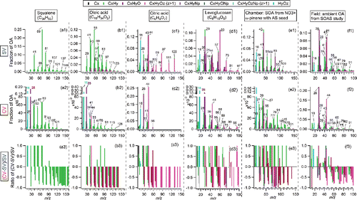
Figure 1. Spectra and comparisons of different pure standard organic compounds: (a) squalene, (b) oleic acid, (c) citric acid, and (d) levoglucosan, between the SV and CV. (e) Chamber SOA generated from NO3+α-pinene with ammonium sulfate (AS) seed, and (f) ambient OA during the SOAS study, between the SV and CV. The top and middle rows are the spectra measured in the SV-AMS and CV-AMS, respectively. The bottom row is the ratio of CV minus SV divided by SV. All the spectra are shown as stacked at unit mass resolution, although they were fit with high-resolution fitting. Only ions contributing more than 1% of total OA to the SV are shown in the differential plot. For squalene, oleic acid, and citric acid, the interference of isopropanol (C3H8O) solvent is less than 5% of total signal and was excluded based on the ratios between the characteristic ion m/z 45 (C3H5O+) and other ions in the pure isopropanol AMS spectrum. Organic H2O+ and CO+ ions from standard compounds were directly calculated using HR-fitting. Organic H2O+ and CO+ ions in chamber SOA were directly calculated using HR fitting. Organic H2O+ ions in the SOAS study was constrained based on organic CO2+ (H2O+/CO2+ = 0.225). Organic CO+ in the ambient CV dataset were calculated based on the enhanced HR-fitted CO+ versus total OA during the OA plumes. Canagaratna et al. (Citation2015) showed that spectral differences among three different SV-AMS instruments were minor.

Figure 2. Summary of direct ion signal ratios between the CV and SV (CV versus SV) for different OA species. Different types of ions (i.e., CxHy+; CxHyO+; CxHyOz+, CxHyN+, CxHyON+) in the spectra at three m/z ranges (i.e., m/z < 50; m/z = 50–100; m/z > 100). To minimize the uncertainties, only ions with abundance in total OA above 1% in the SV spectrum are included in the calculation. Thus, prominent CO+ ion shown in the squalene spectrum measured by the CV is not taken into account due to its low abundance in the spectrum of the SV (<1%). The arrows in the graph indicate the bar on its left side are above the maximum Y values. All the ambient data were obtained in V-mode in AMS, thus the nitrogen-containing ions are hard to be separated. W mode data were used in chamber studies.
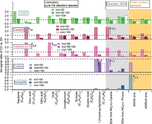
Figure 2. Summary of direct ion signal ratios between the CV and SV (CV versus SV) for different OA species. Different types of ions (i.e., CxHy+; CxHyO+; CxHyOz+, CxHyN+, CxHyON+) in the spectra at three m/z ranges (i.e., m/z < 50; m/z = 50–100; m/z > 100). To minimize the uncertainties, only ions with abundance in total OA above 1% in the SV spectrum are included in the calculation. Thus, prominent CO+ ion shown in the squalene spectrum measured by the CV is not taken into account due to its low abundance in the spectrum of the SV (<1%). The arrows in the graph indicate the bar on its left side are above the maximum Y values. All the ambient data were obtained in V-mode in AMS, thus the nitrogen-containing ions are hard to be separated. W mode data were used in chamber studies.

Figure 3. (a)-(d) Spectra of normal oleic acid from different aerosol generation systems. (e) The calculated spectrum of oleic acid spectra by assuming all carbons to be isotopically- labeled carbons (13C) based on the measured spectrum in (d). (f) Measured spectrum of isotope 13C labeled oleic acid.
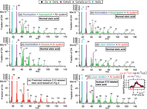
Figure 3. (a)-(d) Spectra of normal oleic acid from different aerosol generation systems. (e) The calculated spectrum of oleic acid spectra by assuming all carbons to be isotopically- labeled carbons (13C) based on the measured spectrum in (d). (f) Measured spectrum of isotope 13C labeled oleic acid.

Figure 4. Results of an experiment slowly alternating beam-open and beam-closed positions while sampling (a) squalene, (b) oleic acid, and (c) citric acid in the CV and (d) citric acid in the SV under vaporizer temperature of 550–600°C. The time interval between datapoints is 4–5 s. τ is the lifetime of signal decay and was estimated with an exponential fit to the relevant part of the time series. An example of exponential fitting line for τ is shown in (a). τ for the rising signal is not shown, since it always varies in the same way as τ for the decay signal. Grey background in graph indicates periods when particle beam is blocked, the white background shows the period when particle beam is open and reaching the vaporizer.
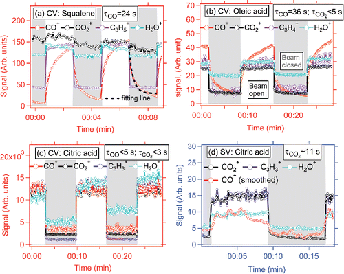
Figure 4. Results of an experiment slowly alternating beam-open and beam-closed positions while sampling (a) squalene, (b) oleic acid, and (c) citric acid in the CV and (d) citric acid in the SV under vaporizer temperature of 550–600°C. The time interval between datapoints is 4–5 s. τ is the lifetime of signal decay and was estimated with an exponential fit to the relevant part of the time series. An example of exponential fitting line for τ is shown in (a). τ for the rising signal is not shown, since it always varies in the same way as τ for the decay signal. Grey background in graph indicates periods when particle beam is blocked, the white background shows the period when particle beam is open and reaching the vaporizer.

Figure 5. Comparison of (a) f44 and (b) f43 between the CV and SV during various laboratory, chamber, and ambient studies. Scatter plots of f44 vs f43 from the (b) CV and (d) SV. Also shown are triangle lines for the SV obtained from Ng et al. (Citation2010) as well as our proposed triangle lines for ambient data only, updated for the CV to guide the eye. The equation for the left line of triangle is estimated to be f44 = −8.148 × f43+0.445, and right line is f44 = −1.964 × f43 + 0.396. KORUS data from research flight 12 (24-May-2016) and 18 (04-June-2016) were used here.
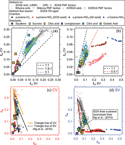
Figure 5. Comparison of (a) f44 and (b) f43 between the CV and SV during various laboratory, chamber, and ambient studies. Scatter plots of f44 vs f43 from the (b) CV and (d) SV. Also shown are triangle lines for the SV obtained from Ng et al. (Citation2010) as well as our proposed triangle lines for ambient data only, updated for the CV to guide the eye. The equation for the left line of triangle is estimated to be f44 = −8.148 × f43+0.445, and right line is f44 = −1.964 × f43 + 0.396. KORUS data from research flight 12 (24-May-2016) and 18 (04-June-2016) were used here.

Figure 6. (a) Regression slopes and correlation coefficients (R) between time series of different ions between CV and SV during the SOAS study. Scatter plots of several tracer ions (b) f43, (c) f60, (d) f82 and (e) f91 between the CV and SV during the SOAS study. All the regressions of scatter plots are determined using orthogonal distance regression with fits forced through zero intercept and in all figures shown below. The vertical black dashed line is the AMS background f60 value (0.3%), calculated based on various non-BB influenced OA plumes in the field studies (Cubison et al. Citation2011). The inset in (c) shows a time series of f60 from the CV and SV for a short period with significant BB impacts. The grey dots are the entire dataset of f60 with a correlation coefficient R of 0.2. The inset of (d) is the scatter plots between f44 vs f82. The black dashed line is the AMS background value of f82 ( = −0.008 × f44 + 0.005), reported in Hu et al. (Citation2015). The grey dashed line is the eye-guided boundary line for IEPOX-SOA influenced triangle areas determined for the SV (Hu et al. Citation2015).
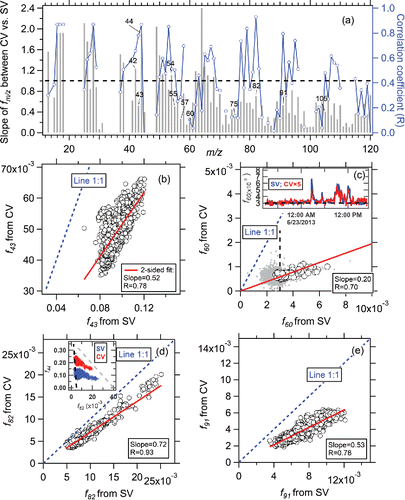
Figure 6. (a) Regression slopes and correlation coefficients (R) between time series of different ions between CV and SV during the SOAS study. Scatter plots of several tracer ions (b) f43, (c) f60, (d) f82 and (e) f91 between the CV and SV during the SOAS study. All the regressions of scatter plots are determined using orthogonal distance regression with fits forced through zero intercept and in all figures shown below. The vertical black dashed line is the AMS background f60 value (0.3%), calculated based on various non-BB influenced OA plumes in the field studies (Cubison et al. Citation2011). The inset in (c) shows a time series of f60 from the CV and SV for a short period with significant BB impacts. The grey dots are the entire dataset of f60 with a correlation coefficient R of 0.2. The inset of (d) is the scatter plots between f44 vs f82. The black dashed line is the AMS background value of f82 ( = −0.008 × f44 + 0.005), reported in Hu et al. (Citation2015). The grey dashed line is the eye-guided boundary line for IEPOX-SOA influenced triangle areas determined for the SV (Hu et al. Citation2015).
Supplemental material

UAST_1454584_Supplementary_file.zip

Download Zip (2.2 MB)

Reprints and Corporate Permissions

Please note: Selecting permissions does not provide access to the full text of the article, please see our help page How do I view content?

To request a reprint or corporate permissions for this article, please click on the relevant link below:

Academic Permissions

Please note: Selecting permissions does not provide access to the full text of the article, please see our help page How do I view content?

Obtain permissions instantly via Rightslink by clicking on the button below:

If you are unable to obtain permissions via Rightslink, please complete and submit this Permissions form. For more information, please visit our Permissions help page.