
Figures & data
Figure 1. Schematic of the degradation environment of a Mg-based alloy screw in bone tissue.
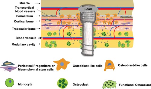
Figure 2. Schematic of the biomechanical environment of a stent in a blood vessel.
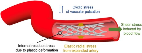
Table 1. Summary of biological processes at cellular and tissue levels that can be mediated by the degradation products of Mg-based alloys.
Figure 3. Representative images showing the formation of porosity in the bone near Mg-based alloy implants. (a) Ex vivo micro-CT 2-D images of bone implant complexes after implantation of LAE442 alloy in NZW rabbit tibia for 12 months [Citation21]. T: tibia; F: fibula; E: endosteal bone formation; C: cavities. (b) Micro-CT images of rat femora implanted with pure Mg or SS rod for 2 weeks [Citation20]. (c) Tartrate-resistant acid phosphatase (TRAP)-stained histological slices of mouse femora cortical bone on the 14th days after implantation with Mg or Ti rods.
![Figure 3. Representative images showing the formation of porosity in the bone near Mg-based alloy implants. (a) Ex vivo micro-CT 2-D images of bone implant complexes after implantation of LAE442 alloy in NZW rabbit tibia for 12 months [Citation21]. T: tibia; F: fibula; E: endosteal bone formation; C: cavities. (b) Micro-CT images of rat femora implanted with pure Mg or SS rod for 2 weeks [Citation20]. (c) Tartrate-resistant acid phosphatase (TRAP)-stained histological slices of mouse femora cortical bone on the 14th days after implantation with Mg or Ti rods.](/cms/asset/add899c8-d81b-427a-a2fd-a5cd6f2b7c79/yimr_a_2079367_f0003_oc.jpg)
Figure 4. Examples of Mg-alloy-based bone-fixation implants. (a) Mg plate and screws for fractured ulna fixation. μCT and toluidine-blue staining of cortical bone after 8 and 16 weeks [Citation376]. (b) Pure-Mg and PLLA screws for femoral intracondylar fracture fixation. μCT scanning of rabbit femur with screws after 4 weeks (red arrows: fracture gap) [Citation277]; (c) SrHPO4-coated JDBM (a Mg–Nd–Zn–Zr alloy) IMNs. Undecalcified sections with Von Gieson staining and μCT 3D reconstruction of rat femurs with IMNs after 8 weeks (red boxes: fracture gap region) [Citation239]; (d) Pure-Mg screw for goat femoral neck fracture fixation, and preoperative and 48-week postoperative μCT 3D reconstruction [Citation380]; (e) Ti/Mg hybrid plate screw system for the fractured tibia fixation (red or blue arrows: Mg screw with PLA coating) [Citation278]; (f) SS/Mg hybrid IMN made by inserting a Mg rod into a hollow stainless steel needle with drilled holes [Citation20].
![Figure 4. Examples of Mg-alloy-based bone-fixation implants. (a) Mg plate and screws for fractured ulna fixation. μCT and toluidine-blue staining of cortical bone after 8 and 16 weeks [Citation376]. (b) Pure-Mg and PLLA screws for femoral intracondylar fracture fixation. μCT scanning of rabbit femur with screws after 4 weeks (red arrows: fracture gap) [Citation277]; (c) SrHPO4-coated JDBM (a Mg–Nd–Zn–Zr alloy) IMNs. Undecalcified sections with Von Gieson staining and μCT 3D reconstruction of rat femurs with IMNs after 8 weeks (red boxes: fracture gap region) [Citation239]; (d) Pure-Mg screw for goat femoral neck fracture fixation, and preoperative and 48-week postoperative μCT 3D reconstruction [Citation380]; (e) Ti/Mg hybrid plate screw system for the fractured tibia fixation (red or blue arrows: Mg screw with PLA coating) [Citation278]; (f) SS/Mg hybrid IMN made by inserting a Mg rod into a hollow stainless steel needle with drilled holes [Citation20].](/cms/asset/f45c5713-657b-43c3-a48d-f1d7d3ff6b23/yimr_a_2079367_f0004_oc.jpg)
Figure 5. Spinal cage made of Mg-based alloys. (a) A hybrid cage consisting of the AZ31 alloy and PCL [Citation391]. Left: AZ31 alloy skeleton of the cage, Right: Cage after infiltration and covering with the PCL; (b) A micro-arc oxidation (MAO)-coated Mg–Zn alloy cage [Citation392]; (c) An MAO-coated AZ31 alloy cage [Citation393].
![Figure 5. Spinal cage made of Mg-based alloys. (a) A hybrid cage consisting of the AZ31 alloy and PCL [Citation391]. Left: AZ31 alloy skeleton of the cage, Right: Cage after infiltration and covering with the PCL; (b) A micro-arc oxidation (MAO)-coated Mg–Zn alloy cage [Citation392]; (c) An MAO-coated AZ31 alloy cage [Citation393].](/cms/asset/a9936794-899f-4813-95eb-710d89172454/yimr_a_2079367_f0005_oc.jpg)
Figure 6. Animal studies and clinical case analysis of Mg-based alloy vascular stents. (a) Haematoxylin-eosin (H&E) staining images and μCT 3D reconstructed images of JDBM (a Mg–Nd–Zn–Zr alloy) stents in rabbit common carotid artery at different time points [Citation407]; (b) Optical coherence tomography 2D images of Magmaris® WE43-alloy-based stent in human coronary artery demonstrated excellent strut apposition with some struts covering the side branch post-implantation; no visible strut remnants exist; and struts initially covering the side branch being resorbed after 12 months [Citation6].
![Figure 6. Animal studies and clinical case analysis of Mg-based alloy vascular stents. (a) Haematoxylin-eosin (H&E) staining images and μCT 3D reconstructed images of JDBM (a Mg–Nd–Zn–Zr alloy) stents in rabbit common carotid artery at different time points [Citation407]; (b) Optical coherence tomography 2D images of Magmaris® WE43-alloy-based stent in human coronary artery demonstrated excellent strut apposition with some struts covering the side branch post-implantation; no visible strut remnants exist; and struts initially covering the side branch being resorbed after 12 months [Citation6].](/cms/asset/a4dc1480-647b-45d3-b3b1-a83bb0c2e9a5/yimr_a_2079367_f0006_oc.jpg)
Figure 7. Animal studies of Mg-based surgical instruments for hemostasis and anastomosis. (a) Mg-Zn-Ca-Y alloy clip occluded the proximal and telecentric stump of rat carotid blood vessels (i), and cuts the blood vessel from the middle of the two hemostatic clips (ii) [Citation420]; (b) Pure-Mg staples for anastomose small intestine (i), and no bleeding and intestinal fluid exudation after anastomosis (ii) [Citation421]; (c) Mg–Zn–Sr intestinal anastomosis ring (i) and surgical procedure of intestinal anastomosis(ii) [Citation422].
![Figure 7. Animal studies of Mg-based surgical instruments for hemostasis and anastomosis. (a) Mg-Zn-Ca-Y alloy clip occluded the proximal and telecentric stump of rat carotid blood vessels (i), and cuts the blood vessel from the middle of the two hemostatic clips (ii) [Citation420]; (b) Pure-Mg staples for anastomose small intestine (i), and no bleeding and intestinal fluid exudation after anastomosis (ii) [Citation421]; (c) Mg–Zn–Sr intestinal anastomosis ring (i) and surgical procedure of intestinal anastomosis(ii) [Citation422].](/cms/asset/3231035e-cf62-446d-9c80-285f6ebc09bd/yimr_a_2079367_f0007_oc.jpg)
Figure 8. Mg-based tissue engineering scaffolds for bone defect repair. (a) Digital and scanning electron microscope (SEM) images of Mg/JDBM-MgF2 scaffold without and with brushite (DCPD) coating. μCT images showing the new bone and vascular formation in the defect area after 4 and 8 weeks (red or white line: bone defect area) [Citation431]; (b) SEM and 2D μCT images of Mg scaffolds; 2D μCT images (red arrows: new bone) and alizarin red S and calcein sequential labels of new bone after 16 weeks [Citation167]; (c) MAO-coated tubular Mg–Zn–Ca scaffold for ulna bone defect repair and X-ray observation after 2, 4, 8 and 12 weeks [Citation433]; (d) A biomimetic-porous Mg material coated with HA/(PEI-SiO2) hybrid layer for femoropatellar defect repair, and a μCT image of femoropatellar bone and the porous Mg [Citation435]; (e) A biomimetic-Mg scaffold for humerus defect repair and X-ray images at various periods [Citation436]; (f) μCT and SEM images of porous alginate/gelatin hydrogel with Mg powder. μCT images, sequential fluorescence staining, H&E staining, and OSX/CD31 immunofluorescence staining of bone formation in defects after 3 weeks, and μCT images of 3D vasculature in defects after 2 weeks, in Blank, Mg free (−Mg) and Mg containing (+Mg) hydrogel groups [Citation437].
![Figure 8. Mg-based tissue engineering scaffolds for bone defect repair. (a) Digital and scanning electron microscope (SEM) images of Mg/JDBM-MgF2 scaffold without and with brushite (DCPD) coating. μCT images showing the new bone and vascular formation in the defect area after 4 and 8 weeks (red or white line: bone defect area) [Citation431]; (b) SEM and 2D μCT images of Mg scaffolds; 2D μCT images (red arrows: new bone) and alizarin red S and calcein sequential labels of new bone after 16 weeks [Citation167]; (c) MAO-coated tubular Mg–Zn–Ca scaffold for ulna bone defect repair and X-ray observation after 2, 4, 8 and 12 weeks [Citation433]; (d) A biomimetic-porous Mg material coated with HA/(PEI-SiO2) hybrid layer for femoropatellar defect repair, and a μCT image of femoropatellar bone and the porous Mg [Citation435]; (e) A biomimetic-Mg scaffold for humerus defect repair and X-ray images at various periods [Citation436]; (f) μCT and SEM images of porous alginate/gelatin hydrogel with Mg powder. μCT images, sequential fluorescence staining, H&E staining, and OSX/CD31 immunofluorescence staining of bone formation in defects after 3 weeks, and μCT images of 3D vasculature in defects after 2 weeks, in Blank, Mg free (−Mg) and Mg containing (+Mg) hydrogel groups [Citation437].](/cms/asset/2fc078f0-361f-4390-91f0-fbd74c314142/yimr_a_2079367_f0008_oc.jpg)