
Figures & data
Figure 1. Maxim silencer design, patent submitted June 26, 1908 (Maxim Citation1909).
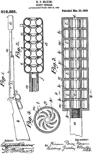
Figure 2. AR-15 pattern short-barreled rifle (SBR*) diagram (major components) with a 5-inch barrel.
*Prior to 2023 this configuration was referred to as an AR Pistol.
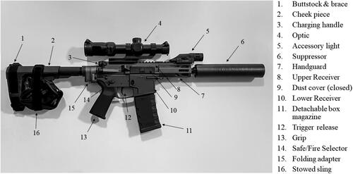
Figure 3. AR-15 pattern SBR (5-inch barrel) exploded parts diagram (major components).
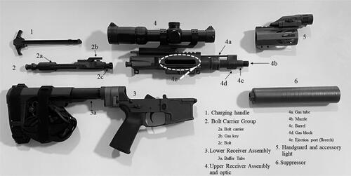
Figure 4. Gas operated bolt and carrier system from E. M. Stoner’s patent drawings. Top panel – cartridge in chamber with the bolt in battery (forward and locked position). Middle panel – bullet has left the case and propellant gasses have traveled through the gas tube and unlocked the bolt. Bottom panel – the propellant gasses have moved the bolt carrier group rearward and the case is about to be ejected from the open breech.
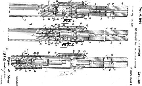
Figure 5. Detail of an AR-15 pattern firearm ejection port (breech) with the dust cover open. Panel A: bolt carrier group in the open position. Panel B: bolt carrier group in the closed and locked position, AKA “in battery.”
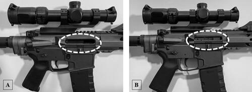
Table 1. Noise floor determination.
Figure 6. The ear-to-breech distance (A) of ∼15 inches (38 cm) is shorter than the ear-to-muzzle distance (B) of ∼26.5 inches (67.3 cm) on this 10.5-inch (26.7 cm) SBR. For a standard 16-inch (40.6 cm) barrel, the breech is 50% closer to the ear than is the muzzle. Note however that the shooter’s left ear Equation(8)(8)
(8) is closer to the muzzle than the right ear, but is shadowed by the skull from the breech. Note that the shooter’s cheek is in contact with the stock/cheek piece forming a cheek weld. Noise transmission to the inner ear via bone conduction was not evaluated as part of this study.
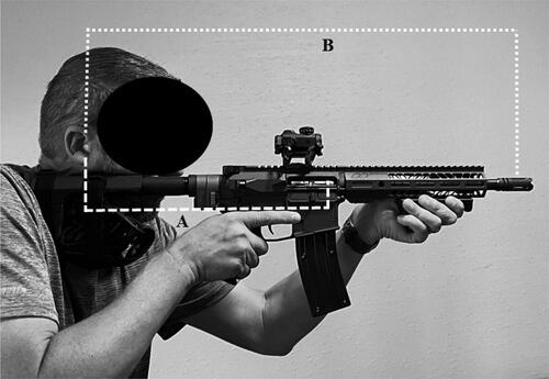
Figure 7. Test configuration.
A – Shooting rest with bolt-action firearm attached.
B – Muzzle inserted through wall with suppressor attached and muzzle microphone placement.
C – Shooting bench and wall with breech and ear microphone placement.
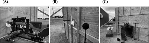
Figure 8. Ambiguity of shooter’s ear location in mil-std-1474E. After Rasmussen et al. (Citation2010) and Keim (Citation1969). The arrow indicates the microphone position described in the standard (15 cm from the ear along the axis between ears). However, this position is closer to the muzzle than the ear (indicated by the large circle). An alternative location is where the large circle intersects a 15 cm circle about the left ear, or where a perpendicular line intersects the same 15 cm circle.
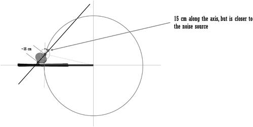
Figure 9. Direct and indirect sound path diagram.
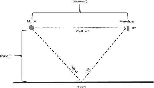
Table 2. Variable configuration and test results.
Figure 10. Target reflection sound path.
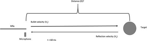
Figure 11. Hyskore DLX Precision Shooting Rest and remote trigger.
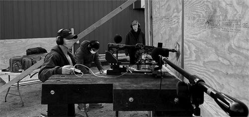
Figure 12. Improvised breech suppressor.
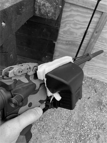
Figure 13. Microphone positions for the left ear (left side of firearm) and breech (right side of firearm).
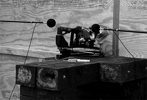
Table 3. Breech suppressor data.
Table 4. Statistical analysis: Summary of tests for wall effect (A–C), breech suppressor tests (D), and miscellaneous tests (E).
Table 5. Action noise: Test results (a), statistical analysis (B).
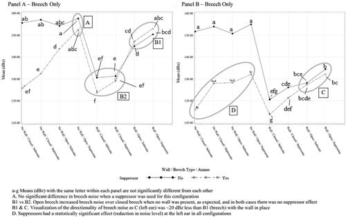
Table 6. Tests of fixed effects, (A) breech, and (B) ear. Pr(>F) is the p value of the F test statistic.
Figure 14. dBz least squares means for each microphone position and configuration, mean dBz values from .
Data availability statement
Analytical data are available upon request from the corresponding author.