Figures & data
Figure 1. The weight-bearing implant model.The implants were inserted into cancellous bone of the distal femur.Ti implants (5.6 mm in diameter) were inserted medially and HA implants (6.0 mm in diameter) were inserted laterally.During weight-bearing, the load was transferred through the polyethylene plug from the tibial plateau to the test implant.Post-mortem, two sections were cut.The first section was used for push-out testing.The second section was used for histomorphometry as serially cut vertical sections were produced after initially random rotating the implant around its long axis.
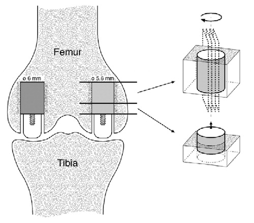
Figure 2. Energy absorption of Ti implants inserted with compaction versus drilling.Paired data from each dog are connected by dashed lines.Solid horizontal lines represent median values.There was no significant difference between compaction and drilling (p = 0.6).
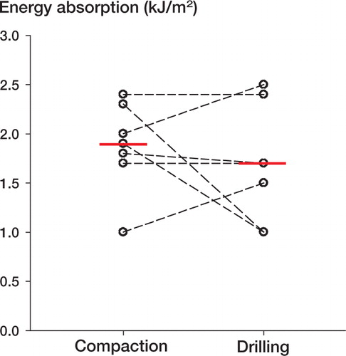
Figure 3. Energy absorption of HA implants inserted with compaction versus drilling.Paired data from each dog are connected by dashed lines.Solid horizontal lines represent median values.There was no significant difference between compaction and drilling (p = 0.8).
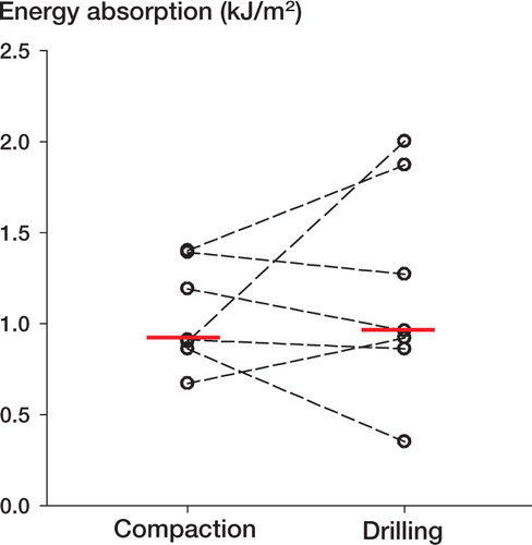
Table 1. Ultimate shear strength (MPa) and apparent shear stiffness (MPa/mm) for Ti implants inserted exactfit into medial condyles, and for HA implants inserted press-fit into lateral condyles. Median values with interquartile ranges are given
Table 2. Tissue implant contact expressed as percentage of the implant surface. Ti implants were inserted exact-fit into medial condyles, and HA implants were inserted press-fit into lateral condyles. Median values with interquartile ranges are given
Table 3. Peri-implant tissue density in a 200-μm periimplant zone. Ti implants were inserted exact-fit into medial condyles, and HA implants were inserted pressfit into lateral condyles. Median values with interquartile ranges are given