Figures & data
Figure 1. The Kudo elbow prosthesis. Upper panel shows both components with a porous coat. Lower panel shows both components without a porous coat. The all-polyethyl-ene ulna component is not pictured.
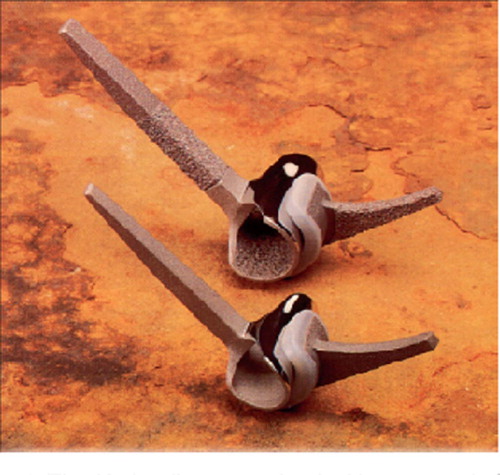
Figure 2. Schematics used to determine the malalignment of the components. A–D: ideal alignment of the components; the axis of the component is parallel to the defined axis of the humerus and ulna, respectively. Deviation from the axis in valgus-varus and flexion-extension was measured in degrees (arrow).
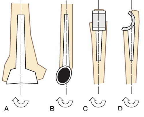
Figure 3. Postoperative lateral and AP radiograph (case 25; Table). The humeral component is positioned in varus; the ulnar component is positioned in varus and flexion. The malalignment relative to the axis of the bone is illustrated. Also, note the subluxation with valgus tilt of the prosthesis.
Details of all 49 patients in the series
Figure 4. Lateral and AP radiographs of the same prosthesis as in , 2 years after insertion. There is marked osteolysis around the ulnar stem (white arrows).
Figure 5. Lateral and AP radiographs of the same prosthesis at the time of revision (4.6 years after implantation); osteolysis around the ulnar stem has caused fracture of the ulna (white arrows).
Legends to Table