Figures & data
Figure 4. Digital microscopy of the junctional discoloration, i.e., corrosion products.
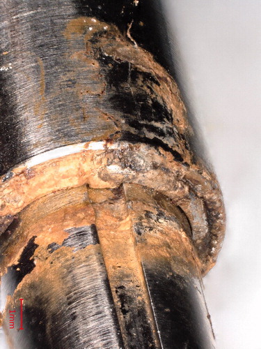
Table 1. Symptoms, radiographic changes, and metallurgical characteristics of the 30 STRYDE-lengthened bone segments
Figure 6. Micro-CT of 2 STRYDE and 1 PRECICE P2. Overview and detailed imaging of the bushing/crown, O-rings and ball bearing. Corrosion is seen around the bushing/crown in 12/12 nails scanned at this location (middle panel), corrosion at the O-ring was observed in 1/5 nails scanned at this location (top panel). Notably, no signs of corrosion were seen around the ball bearing in 4/4 scanned nails at this location. No corrosion was seen in the reference PRECICE P2 nail at any location. The mechanical components inside the housing appeared to be similar between STRYDE and PRECICE P2.
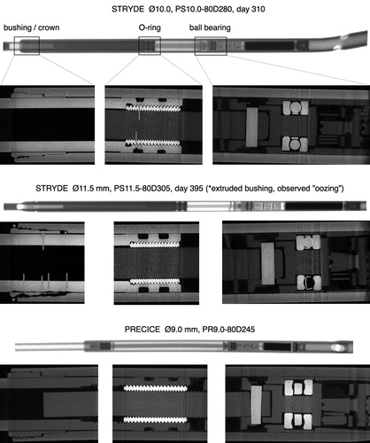
Figure 8. Examples of a sectioned STRYDE (top panel), corroded bushing (middle panel), and presence of biological material on internal components. Biological origin was verified with EDS analysis showing a high oxygen content (bottom panel).
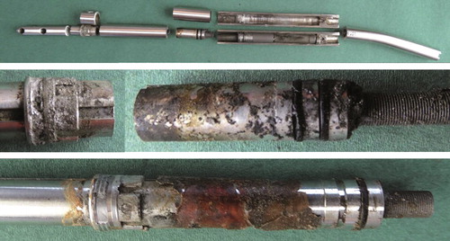
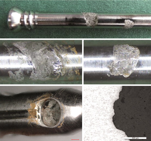
Figure 9. Corrosion attack at the bushing/crown. Digital microscopy (upper panels) and microscopy of the microstructure (middle and lower panels).
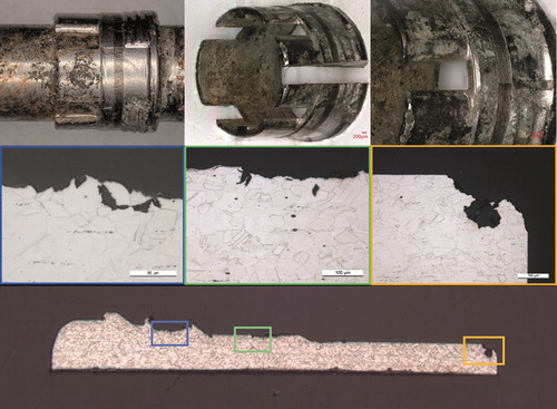
Figure 10. Mechanically assisted crevice corrosion/fretting and crevice corrosion at a locking screw, screw hole including microscopic image of the corrosion-attacked microstructure. For SEM imaging see Figures 12 and 13 in Supplementary data.