Figures & data
Figure 1. The medieval harbour town of Hoeke was located in the centre of the Bruges outer harbour system, situated along the tidal inlet “Zwin”. (Copyright: Ghent University).
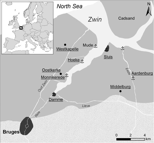
Figure 2. Location of the test-pit within the concentration of high electric values in geophysical EMI-survey and related to the scattering of iron slags found at the surface of the site. (Copyright: Ghent University).
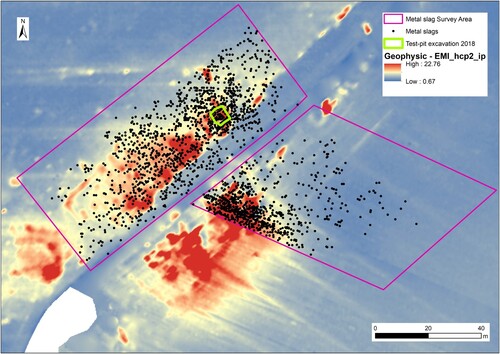
Figure 3. Photographs of iron production debris found at the Hoeke site. (A) is a sample representing the first (1) microscopical group, (B), is a sample representing the second (2) group, (C) represents a PCB slag, and (D) is an iron slag sample with technical ceramics attached to the surface. (E) shows an example of a slag with imprints of partially melted sand on the surface. The vesicular texture of the slag from the second (2) group is shown in F.
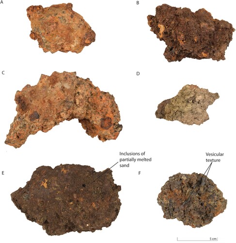
Figure 4. XRD patterns of three selected slags from Hoeke. Fa – fayalite, FeAl – iron aluminium silicate, W – wüstite, M – magnetite, Q – quartz, J – jarosite, An – anorthoclase.
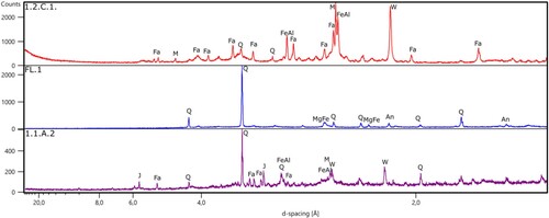
Table 1. Mineralogical composition based on the XRD results for the iron slag samples from Hoeke. S – surface, FL – clay attached, PCB – Plano Convex Bottom slag, HS – Hammer Scales.
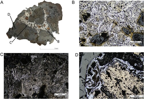
Figure 5. Optical photomicrographs of polished sections in reflected light. (A) is characterized by long laths of fayalite (Fa) in a siliceous matrix. The white dots are inclusions of metallic iron (Fe). At the bottom of the photo, there are some traces of organic matter – coal (org). (B) is generally composed of fayalite (Fa) and magnetite (Ma), accompanied by the presence of metallic iron inclusions (Fe). Texture (C) demonstrates elongated fayalite forming a spinifex texture that is associated with a fast cooling rate. (D) is characterized by wüstite (Wu) and magnetite crystals (Ma). The presence of wüstite both in a dendrite and globular form indicates variable cooling conditions, with faster cooling in the areas within which the dendrites are formed. Sample (E) is mainly dominated by well-developed wüstite dendrites (Wu). (F) is representing a fluidal texture (MS), which suggests the application of a high temperature. All the photomicrographs were taken under plane-polarized light unless otherwise stated.
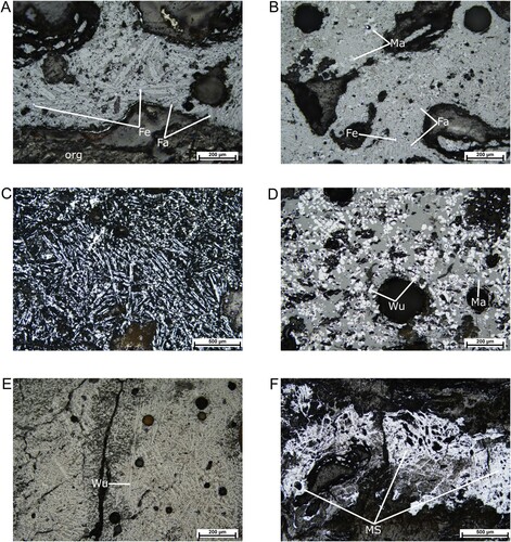
Figure 6. Photograph and microphotograph of a sample with a large metallic band (A). The sample is etched with 2% nital. The microstructure of this specimen is characterized by the occurrence of a large amount of iron spread throughout the sample. The letters on the photograph indicate the following photomicrographs. In (B) and (C), the uneven distribution of ferrite iron with pearlite grains within one sample can be observed. (D) presents a partial melting structure with traces of coal.