Figures & data
Figure 1 Apoptotic ADCSs induction and apoSEV isolation and characterization. (A) Schematic illustration of apoptotic ADSCs induction and apoSEV isolation. (B and C) The cellular morphology and flow cytometry analysis (B), and TUNEL immunofluorescent staining (C) of normal ADSCs and STS induced apoptosis ADSCs. Scale bar = 50 μm. (D) Representative image showing the morphology of apoSEV and apoBD by TEM. Scale bar = 500 nm. (E) The size distribution of apoSEV analyzed by NTA. (F) The presence of Caspase-3/Cleaved Caspase-3 in ADSC, apoSEV, and ApoBD analyzed by Western Blot. (G)Schematic illustration of the procedure for obtaining apoSEV and EV with the same number of ADSCs. (H and I) Quantification of the particle concentration (H) and the protein ratio of EV to cell (I). The data in the figures represent the mean ±SD. Significant differences between groups are indicated as * P< 0.05; ** P < 0.01.
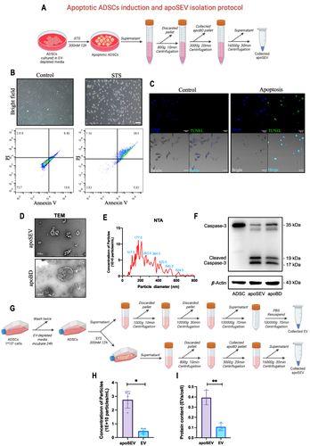
Figure 2 apoSEV inhibited the inflammatory response by increasing the ratio of M2 polarization macrophages to M1 polarization in vitro. (A) Schematic illustration of apoSEV promoted M2 macrophage polarization and reduced inflammation in the phase of inflammatory response. (B) The morphology of Raw264.7 cells treated with LPS, LPS+EV, LPS+apoSEV, and LPS+apoBD. Scale bar = 100 μm. (C and D) immunofluorescence staining of M1 macrophage marker NOS2 (C) and M2 macrophage marker CD206 (D). Scale bar = 50 μm. (E and F) Quantification of the ratio of NOS2 to F4/80 (E) and the ratio of CD206 to F4/80 (F). (G) The M1 and M2 macrophage relative gene expressions of iNOS, IL-1β, TNF-α, IL-6, TGFβ, CD206 and IL-10 were detected by qRT-PCR. The data in the figures represent the mean ± SD. Significant differences between groups are indicated as *P< 0.05; **P < 0.01; ***P < 0.001; ****P < 0.0001; NS, not significant.
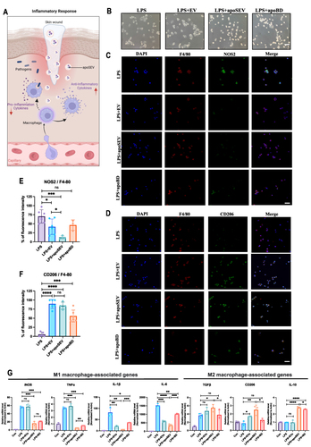
Figure 3 apoSEV promoted the proliferation, migration, and tube formation of HUVEC. (A) Schematic illustration of apoSEV promoted cellular function recover of the endothelia cells and fibroblast in the phase of proliferative. (B) The effects of apoSEV, EV and apoBD on HUVEC proliferation under high glucose conditions was examined by CCK8 assay. (C and D) Representative images showcasing the wound closure progress of HUVECs in various experimental groups, as determined through the cell scratch assay at the 12-hour and 24-hour time points (D). Scale bar = 200 μm. Statistical analysis of migration area (%) in scratch assay (C). (E and G) Representative images of transwell migration assay of HUVECs in different groups (E). Statistical analysis of migrated number of HUVECs in transwell assay (G). (F, H and G) Tube formation of HUVECs with different treatment. Scale bar = 200 μm. (F) Statistical analysis of total junction and branch points representing tube formation ability (H and I). The data in the figures represent the mean ±SD. Significant differences between groups are indicated as * P< 0.05; ** P < 0.01; *** P < 0.001; NS, not significant.
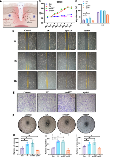
Figure 4 apoSEV promoted the proliferation and migration of HDFs. (A) The effects of apoSEV, EV and apoBD on HDFs proliferation under high glucose conditions was examined by CCK8 assay. (B and D) Representative images showcasing the wound closure progress of HDFs in various experimental groups, as determined through the cell scratch assay at the 12-hour and 24-hour time points (D). Statistical analysis of migration area (%) in scratch assay (B). Scale bar = 200 μm. (E and C) Representative images of transwell migration assay of HDFs in different groups (E). Statistical analysis of migrated number of HDFs in transwell assay (C). The data in the figures represent the mean ±SD. Significant differences between groups are indicated as * P< 0.05; ** P < 0.01.
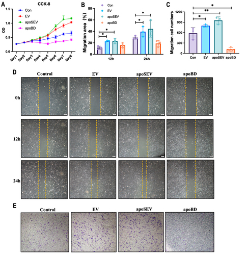
Figure 5 Characterization of GelMA and GelMA+apoSEV hydrogel. (A) The representative SEM images of GelMA hydrogels at different concentrations. Scale bar = 100 μm. (B) Mean pore size of the GelMA hydrogels at different concentration. (C) Storage and loss modulus of the GelMA hydrogels at different concentration. (D) Swelling ratio of the GelMA hydrogels at different concentration. (E) Degradation ratio of the GelMA hydrogels at different concentration. (F) Cytotoxicity of the GelMA hydrogels tested by CCK8. (G) Reconstruction 3D image illustrating 10% photo-crosslinked GelMA hydrogels containing apoSEVs labeled with PKH26. Scale bar = 100 μm. (H) Representative confocal images display HDFs co-cultured with PKH26 labeled apoSEVs (red) in both their free form and GelMA-incorporated form, with nuclei stained using DAPI (blue). Scale bar = 50 μm. The data represent the mean ±SD in the figures. Significant differences between groups are indicated as * P< 0.05; ** P < 0.01; *** P < 0.001; **** P < 0.0001.
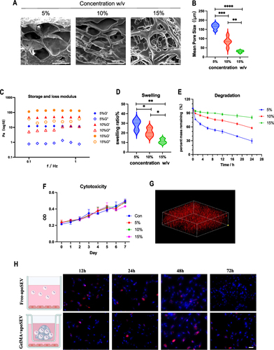
Figure 6 ApoSEV accelerates the rate of wound healing in vivo. (A) The gross view of wounds closure of Control, GelMA, GelMA+EV and GelMA+apoSEVs groups at day 0, 4, 7, 10 and 14. (B) Simulation plots of the wound closure areas at different time points and overlapped visualization groups. (C) Quantitative evaluation of the wound closure rate.The data represent the mean ±SD in the figures. Significant differences between groups are indicated as * P< 0.05.
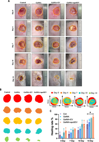
Figure 7 ApoSEV promotes wound healing and angiogenesis. (A) H&E staining of regenerated skin tissue in Control, GelMA, GelMA+EV and GelMA+apoSEV groups at day 14. Scale bar = 100 μm. (B) Masson staining of regenerated skin wounds in different groups at day 14. Scale bar = 100 μm. (C) Immunohistochemical staining of VEGF in regenerated skin tissue in different groups at day 14. (D) immunofluorescence staining of CD31 in regenerated skin tissue in different groups at day 14. Scale bar = 100 μm. (E) Quantitative analysis of collagen ratios of Masson staining of regenerated skin wounds in different groups at day 14. (F) The quantitative analysis of the relative mean density of immunohistochemical staining for CD31 in regenerated skin tissue among various experimental groups on day 14. The data represent the mean ±SD in the figures. Significant differences between groups are indicated as * P< 0.05; ** P < 0.01; *** P < 0.001.
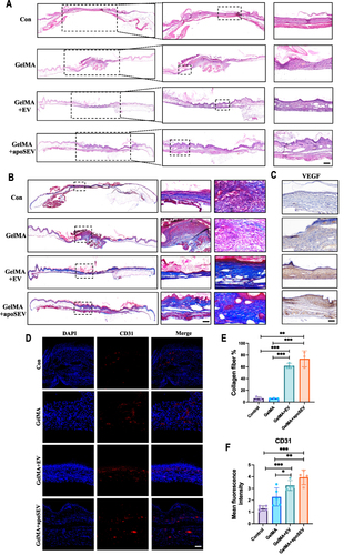
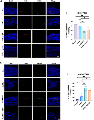
Figure 8 ApoSEV promoted an increase in the ratio of M2 polarization macrophages to M1 polarization in vivo. (A and B) immunofluorescence staining of M1 macrophage marker NOS2 (C) and M2 macrophage marker CD206 in regenerated skin tissue in different groups at day 14. Scale bar = 100 μm. (C and D) Quantitative analysis the ratio of relative mean density of immunohistochemical staining of NOS2 and CD206 to F4/80 in regenerated skin tissue among various experimental groups on day 14. The data represent the mean ±SD in the figures. Significant differences between groups are indicated as * P< 0.05; ** P < 0.01; *** P < 0.001.