Figures & data
Figure 1. Round window (RW)-Coupler. The RW-Coupler was provided by MED-EL Co.
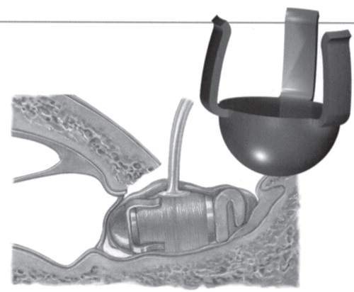
Figure 2. Otoscopic findings of tympanic membrane. The right external auditory canal was expanded (A) and sclerotic lesion was found in the left tympanic membrane (B).
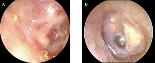
Figure 3. Pure-tone audiogram. (A) Bilateral mixed hearing loss was present. (B) Left hearing level was not changed after the VSB surgery.
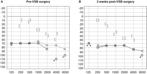
Figure 4. CT scan of region of the round window (RW) in our case. (A) Right ear, (B) left ear, and (C) control case. The RW in our case was remarkably small compared with the control case. The diameter of the RW is shown as arrowheads in the schematic representation.
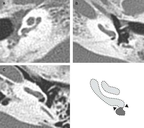
Table I. Outcomes of audiological tests in open field.
Figure 5. Warble tone threshold level. Compared with the threshold level of the conventional hearing aid (A), the threshold level of the VSB at the first fitting was improved at the high frequencies (B). After refitting, amplification at the low frequencies was elevated (C).
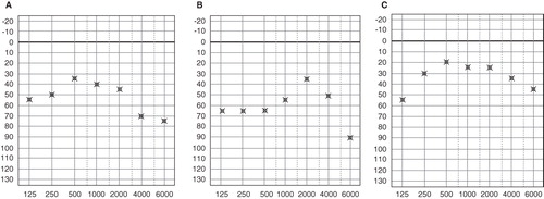
Figure 6. Floating mass transducer (FMT) with round window (RW)-Coupler placement in the RW. The FMT attached with RW-Coupler was placed in the RW (A) after good fitting of the RW-Coupler (arrow) was confirmed (B). The FMT was wrapped in perichondrium (C).
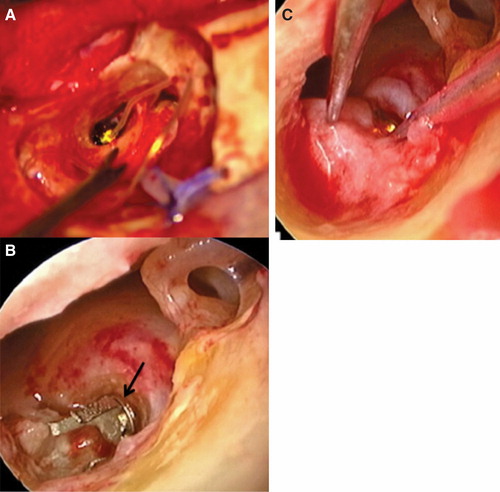
Figure 7. X-P finding of floating mass transducer (FMT) placement after VSB surgery. Good placement of the FMT with the round window (RW)-Coupler was confirmed. Scheme of X-P is shown. Lscc, lateral semicircular canal; Sscc, superior semicircular canal.
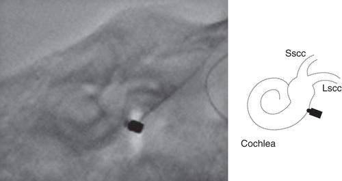
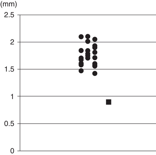
Figure 8. Diameter of the round window (RW) by radiologic evaluation of CT scan. The diameter was measured on the inferior edge of the RW in the transverse slice in the left ear. This case (black square) was remarkably small compared with control cases (black circles). Patients with sensorineural hearing loss were measured as control cases.