Figures & data
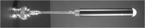
Figure 1. New and existing prototypes of 27.12 MHz radiators developed for endocavitary hyperthermia (EHT) of small-radius cavities. (1A) the inductive helix (H) radiator; (1B) the new inverse capacitive current (C) applicator; (1C) the new inductive toroidal (T) radiator; and (1D) the existing helix U-10 radiator Citation[32] included for comparison. Physical data for each radiator are provided in .
![Figure 1. New and existing prototypes of 27.12 MHz radiators developed for endocavitary hyperthermia (EHT) of small-radius cavities. (1A) the inductive helix (H) radiator; (1B) the new inverse capacitive current (C) applicator; (1C) the new inductive toroidal (T) radiator; and (1D) the existing helix U-10 radiator Citation[32] included for comparison. Physical data for each radiator are provided in Table I.](/cms/asset/0016c330-2b7b-4d49-ac81-4bbf61f427ad/ihyt_a_521886_f0001_b.gif)
Table I. Radiators and heads physical data. Radiator circuits lie over the surface of a cylindrical insulating mandrel (); L and OD are radiator length and diameter; the U-10 helix radiator data are retrieved from Citation[32]. The TAA, CAW and HAW interface includes a cannula forming inner and outer interstices to be filled with specific dielectric media (); the CAW length is inclusive of both electrodes; heads cross-sections are in and longitudinal sections in . Data in mm.
Figure 2. Schematic view and reference system of an RF head in the phantom cavity. The bottom-tapped thin cannula covers the RF radiator to establish inner and outer interstices that are filled with the specific dielectric media combination of the matching interface.
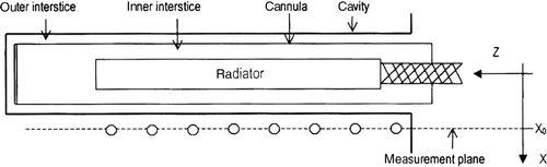
Figure 3. Cross-sectional view of TAA, HAW and CAW in the phantom cavity (not shown). The outlined components are: the insulating mandrels (grey sections) supporting the radiator structures, i.e., the four outer loop sides of the T-radiator, the helix winding of the H-radiator, and the capacitive electrodes of the C radiator. The head cannulae (dashed lines) separate the inner and outer interstices to be filled with air (A) and/or non-conducting water (W) in each radial specific matching sequence. The H, C, and T radiator prototypes are shown in , physical data of the radiators and their matching interfaces in , and longitudinal sections of all the heads in .
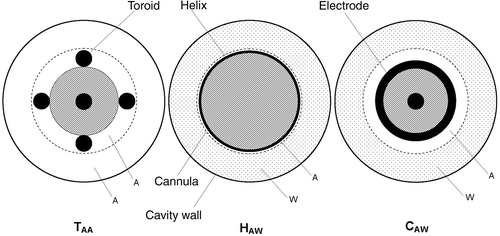
Figure 4. Cavity phantom with the temperature measurement assembly Citation[32].
![Figure 4. Cavity phantom with the temperature measurement assembly Citation[32].](/cms/asset/42111c9c-07df-4fa8-8dfd-c871641ed618/ihyt_a_521886_f0004_b.gif)
Table II. Time constant t of capillary-thermocouple assembly immersed in controlled water bath at 24 ± 0.1°C. Capillaries are of different materials: Teflon, poly-urethane, glass, and of different OD and thickness; t is the readout time at 95% of the exponential temperature-time curves. OD and ID are in mm, t in s.
Figure 5. Radial iso-SAR normalized contours above the 50% SAR efficacy level for T-heads, each with a different matching interface consisting of a dual interstitial gap filled with either air (A) and/or non-conducting water (W) in different radial sequences: (top) TAW head, (middle) TWW head, (bottom) TAA head. The TAA is the only acceptable performer and the related D1/2 parameter is provided in . The heads longitudinal sections are depicted in the diagrams. The TAA cross-section is shown in and the physical data in .
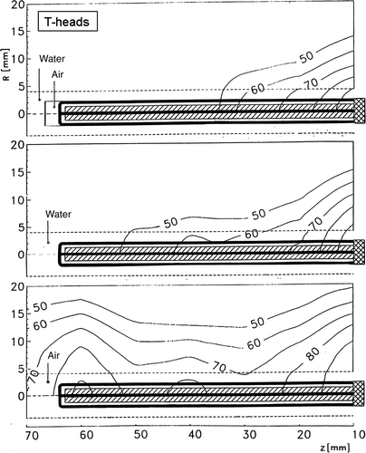
Figure 6. Radial iso-SAR normalized contours above the 50% SAR efficacy level for H-heads, each with a different matching interface consisting of a dual interstitial gap filled with either air (A) and/or non-conducting water (W) in different sequences: (top) HAW head, (middle) HWW head, (bottom) HAA head. The HAW is the only acceptable performer and the related D1/2 parameter is provided in . The heads longitudinal sections are depicted in the diagrams. The HAW cross-section is shown in and the physical data in .
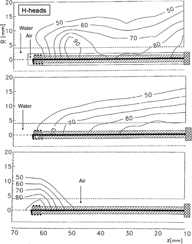
Figure 7. Radial iso-SAR normalized contours above the 50% SAR efficacy level for C-heads, each with a different matching interface consisting of a dual interstitial gap filled with either air (A) and/or nonconducting water (W) in different radial sequences: (top) CAW head, (middle) CWW head, (bottom) CAA head. The CAW is the only acceptable performer and the related D1/2 parameter is provided in . The heads longitudinal sections are depicted in the diagrams. The CAW cross-section is shown in and the physical data in .
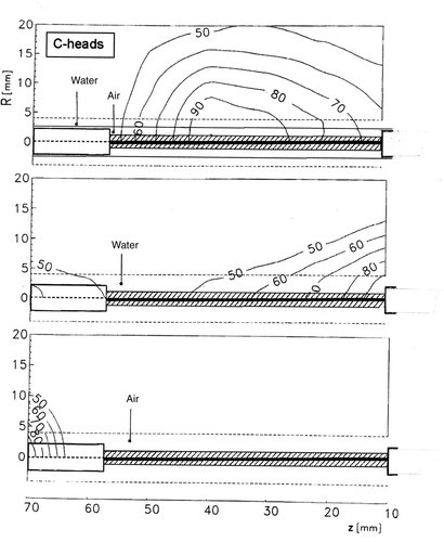
Figure 8. Normalized longitudinal SAR profiles above the 50% SAR efficacy level for the TAA, HAW and CAW heads constructed with data retrieved from the iso-SAR contours of and from . The profiles of the HLDA dipole Citation[8] and of the U-10 RF radiator Citation[32] are added for comparison. Included are traces of the active lengths of the radiators and the trace of the 80% SAR level, which are used to evaluate the numerical parameters of the profiles: Z50, Leff, Q80, d-GZ, and p-Gz that are provided in . Physical data of the heads are provided in .
![Figure 8. Normalized longitudinal SAR profiles above the 50% SAR efficacy level for the TAA, HAW and CAW heads constructed with data retrieved from the iso-SAR contours of Figures 5–7 and from Table I. The profiles of the HLDA dipole Citation[8] and of the U-10 RF radiator Citation[32] are added for comparison. Included are traces of the active lengths of the radiators and the trace of the 80% SAR level, which are used to evaluate the numerical parameters of the profiles: Z50, Leff, Q80, d-GZ, and p-Gz that are provided in Table III. Physical data of the heads are provided in Table I.](/cms/asset/75ebd758-1674-4db0-acc4-f9d6b7fc4421/ihyt_a_521886_f0008_b.gif)
Table III. RF heads heating features. The CAW Leff is inclusive of both ring electrodes and for both inductive HAW and TAA heads a pair of SAR maximum show up at each Z50 end (). The heating features of the RF U-10 radiator and of the MW HLDA, dipole and helix antennae are added for comparison: the HLDA D1/2 values are taken off the hot spot and at the hot spot (in parenthesis). Data are in mm: precision: ±15% (this work), ±20% (other sources).
Table IV. Heating features qualitative synopsis of RF heads, RF radiators and MW applicators for EHT.
Figure 9. Radial iso-SAR normalized contours of the 27.12 MHz U-10 helix radiator assessed by direct insertion in the phantom bulk, protected by a thin Mylar film, and retrieved for comparison from Citation[32]. The U-10 helix radiator is shown in and the physical data in . The D1/2 parameter is provided in .
![Figure 9. Radial iso-SAR normalized contours of the 27.12 MHz U-10 helix radiator assessed by direct insertion in the phantom bulk, protected by a thin Mylar film, and retrieved for comparison from Citation[32]. The U-10 helix radiator is shown in Figure 1 and the physical data in Table I. The D1/2 parameter is provided in Table III.](/cms/asset/5b2606d6-10f1-470d-8a43-f5c6ab37a321/ihyt_a_521886_f0009_b.gif)
Figure 10. Prototype of the 27.12 MHz pre-optimized 8 mm OD inductive HAW head, equipped with the bi-layer interface (), and externally protected with a thin cannula as exemplified for direct insertion into a cavity of compatibly resilient OD.