378
Views
5
CrossRef citations to date
0
Altmetric
RESEARCH ARTICLE

Partial splenectomy using an electromagnetic thermal surgery system in a porcine model

, , , , &
Pages 108-115 | Received 09 Jun 2010, Accepted 05 Oct 2010, Published online: 21 Mar 2011

Figures & data

Figure 1. A schematic diagram of the electromagnetic thermal surgery system used in the study. The system was designed in our laboratory and custom-made by a commercial manufacturer.
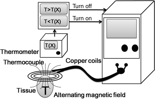
Figure 1. A schematic diagram of the electromagnetic thermal surgery system used in the study. The system was designed in our laboratory and custom-made by a commercial manufacturer.

Figure 2. Comb-needle array used in this study. Note that the conductive coil and plug provide feedback to the control system to obtain the correct needle temperature. There is a temperature sensor embedded in one of the needles, which is connected with the plug. The needles are separated by 0.5 cm and can be of various lengths. The needle array has a protective pad over the sharp end. The pad will be applied after tissue penetration and before heating.
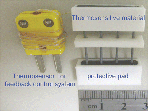
Figure 2. Comb-needle array used in this study. Note that the conductive coil and plug provide feedback to the control system to obtain the correct needle temperature. There is a temperature sensor embedded in one of the needles, which is connected with the plug. The needles are separated by 0.5 cm and can be of various lengths. The needle array has a protective pad over the sharp end. The pad will be applied after tissue penetration and before heating.

Figure 3. Procedures of the partial splenectomy using the electromagnetic thermal surgery system. (A) The needle arrays were inserted 15 cm from the tip of the spleen. (B) After heating, the Thermolite attached to the needle arrays changed colour from black to white when the temperature was above 70°C. (C-D) The cut surfaces of the spleen showed effective coagulation without signs of oozing.
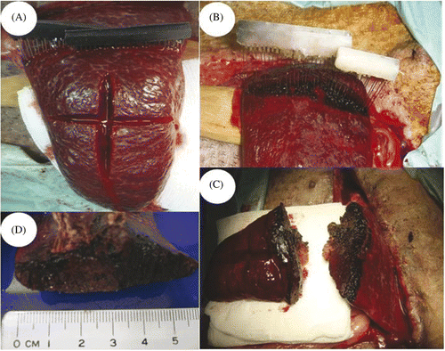
Figure 3. Procedures of the partial splenectomy using the electromagnetic thermal surgery system. (A) The needle arrays were inserted 15 cm from the tip of the spleen. (B) After heating, the Thermolite attached to the needle arrays changed colour from black to white when the temperature was above 70°C. (C-D) The cut surfaces of the spleen showed effective coagulation without signs of oozing.

Figure 4. Histological examination of surgical margins. (A) Control splenic tissue (A1) was positive for NADPH-diaphorase activity (A2) and showed apoptosis only within the white pulp under TUNEL assay (A3). (B) Immediately resected spleen (B1) showed loss of NADPH (B2) in necrotic area (N) compared to viable splenic tissue (V). Increase of apoptosis in necrotic area was also noted (B3). (A1, A2, B-1, and B2: magnified 10×; A3 and B3: 100×).
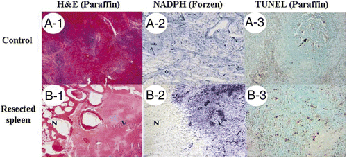
Figure 4. Histological examination of surgical margins. (A) Control splenic tissue (A1) was positive for NADPH-diaphorase activity (A2) and showed apoptosis only within the white pulp under TUNEL assay (A3). (B) Immediately resected spleen (B1) showed loss of NADPH (B2) in necrotic area (N) compared to viable splenic tissue (V). Increase of apoptosis in necrotic area was also noted (B3). (A1, A2, B-1, and B2: magnified 10×; A3 and B3: 100×).

Figure 5. Histological examinations of remnant spleen. (A) The remnant spleen was removed 14 days after the procedure; arrow points to the dense adhesions. Histological examination showed a fibrous band (F) between viable splenic tissue (V) and necrotic tissue (N) (B: HE stain; C: Masson's trichrome stain; D: NADPH stain, for viability from frozen section; E: TUNEL assay from paraffin block; B-D: 10×, E: 100×).
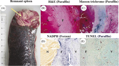
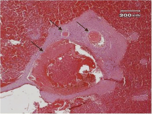
Figure 5. Histological examinations of remnant spleen. (A) The remnant spleen was removed 14 days after the procedure; arrow points to the dense adhesions. Histological examination showed a fibrous band (F) between viable splenic tissue (V) and necrotic tissue (N) (B: HE stain; C: Masson's trichrome stain; D: NADPH stain, for viability from frozen section; E: TUNEL assay from paraffin block; B-D: 10×, E: 100×).

Figure 6. The blood vessels (arrow) near the resected margin of the spleen showed thrombus formation (40×).

Figure 6. The blood vessels (arrow) near the resected margin of the spleen showed thrombus formation (40×).

Reprints and Corporate Permissions

Please note: Selecting permissions does not provide access to the full text of the article, please see our help page How do I view content?

To request a reprint or corporate permissions for this article, please click on the relevant link below:

Academic Permissions

Please note: Selecting permissions does not provide access to the full text of the article, please see our help page How do I view content?

Obtain permissions instantly via Rightslink by clicking on the button below:

If you are unable to obtain permissions via Rightslink, please complete and submit this Permissions form. For more information, please visit our Permissions help page.