Figures & data
Figure 1. Tumour sphere (shaded grey; tumour centre T and tumour radius rt), safety margin sphere (non-shaded; safety margin s, centre C* (= T) and radius rc*) and coagulation centre C with ECC (marked as blue line); rc* = rt + s and ECC = √(). Since the tumour centre and coagulation centre are always defined in the x/y-plane, the coagulation centre always has the coordinate C (ex, ey, 0).
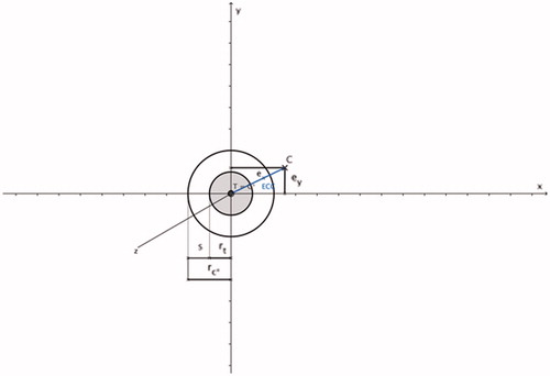
Figure 2. Spherical coagulation zone (shaded in yellow; coagulation centre C), coagulation radius rc and applicator (marked in red). The direction of the applicator shaft (marked as a red line) is always defined in the x-axis direction; the applicator shaft crosses the coagulation centre C and the applicator tip (marked as a red arrowhead) ends at the surface point Pc on the coagulation margin; the coagulation centre is always defined in the x/y-plane.
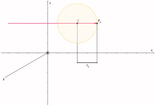
Figure 3. Coagulation radius rc of the optimised coagulation zone (shaded in yellow; coagulation centre C) can be calculated: rc = ECC + rt + s. Based on and .
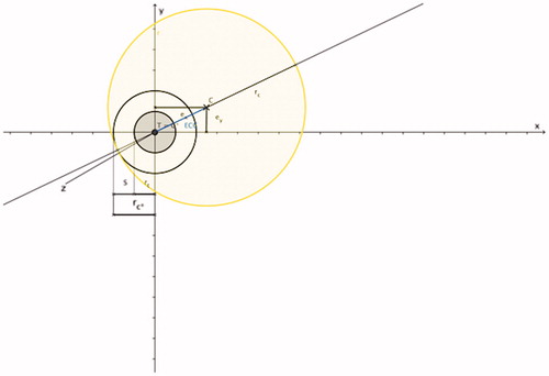
Figure 4. PAO indicates the radial distance in x-axis direction (applicator shaft direction) between surface point Pc on the coagulation margin and surface point Pt on the tumour margin: PAO = ECC + ex + s. Based on , and ; PAO is the radial distance between two work planes (work plane Et perpendicular to the x-axis intersecting surface point Pt and work plane Ec perpendicular to the x-axis intersecting surface point Pc).
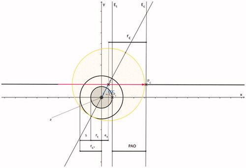
Figure 5. Feasibility of CT-guided thermal ablation by using 3D image post-processing with definition of the master image slice. (A–C, E, F) Standard image planes (transversal, coronal and sagittal). (D, G, H) Master image slice. Positioning of the applicator using standard image planes (A–C). In the standard image planes, the entire course of the applicator shaft (A, E), as well as a fictive tumour centre (white X) (F) did not appear in one single image slice. After individual image angulation the entire course of the applicator shaft as well as the fictive tumour centre (white X) became obvious in one single image slice (master image slice) (D, G, H) with x-axis and y-axis as defined in the Cartesian coordinate system. The direction of the x-axis (red) defined the direction of the applicator shaft; the y-axis (yellow) was defined as being perpendicular to the applicator shaft. In the master image slice, the distance between the applicator shaft and the tumour centre (white X) defines ey (green) (H).
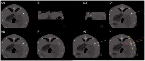
Figure 6. PAOspec indicates the radial distance in x-axis direction (applicator shaft direction) between the applicator tip (Pspec) and the surface point Pt on the tumour margin: PAOspec = CC + ex – rt.Based on ; ellipsoid coagulation zone (shaded in green; applicator (marked in orange); PAOspec is the radial distance between two work planes (work plane Et is perpendicular to the x-axis and intersects with surface point Pt and work plane Espec is perpendicular to the x-axis and intersects with surface point Pspec); CC is the distance between the projection of the site of the coagulation short diameter on the applicator shaft (C) and the applicator tip (Pspec); the front margin (FM) is the distance between the distal edge of the coagulation zone (Pc_spec) and the applicator tip (Pspec).
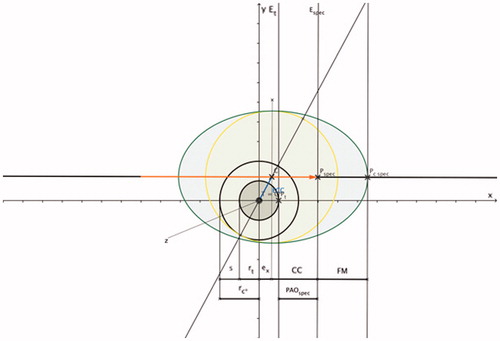
Table 1. Optimised coagulation zone for a tumour diameter of 1 cm (3 cm) and a safety margin of 0.5 cm for spherical coagulation shapes.
Figure 7. Relationship between ECC and the optimised coagulation volume. The larger the ECC, the larger the optimised coagulation zone; the optimised coagulation volume is larger for ellipsoid coagulation shapes (B), compared with spherical coagulation shapes (A); for identical numerical values of ECC, PAOs (PAOsspec) can be different depending on the dislocation of the coagulation centre in relation to the tumour centre (see Tables).
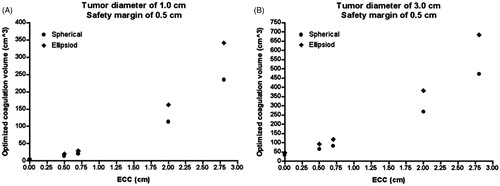
Table 2. Optimised coagulation zone for a tumour diameter of 1 cm (3 cm) and a safety margin of 0.5 cm for ellipsoid coagulation shapes.
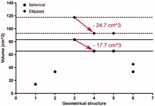
Figure 8. Minimisation of the optimised coagulation zone after positioning of the applicator without the need for repuncture (neutralisation of ex). 1 (on the geometrical structure axis), tumour sphere (diameter of 3.0 cm); 2, safety margin sphere (safety margin of 0.5 cm); 3–6, optimised coagulation zone for spherical (point) and ellipsoid (diamond) coagulation shapes (3, ex = 0.5 cm and ey = 0.5 cm; 4, ex = 0 cm and ey = 0.5 cm; 5, ex = 0.5 cm and ey = 0 cm; 6, ex = 0 cm and ey = 0 cm). After neutralisation of ex (ex = 0 cm) (red arrow), for spherical (ellipsoid) coagulation shapes an unnecessary coagulation volume of 17.7 cm3 (24.7 cm3) can be eliminated by slightly adjusting the applicator shaft by pulling back or pushing forward (for spherical (ellipsoid) coagulation shapes by reduction of PAO (PAOspec) from 1.7 cm to 1.0 cm (1.6 cm to 1.0 cm)).