
Figures & data
Figure 1. A historical timeline of FUS neurosurgical intervention [Citation76].
![Figure 1. A historical timeline of FUS neurosurgical intervention [Citation76].](/cms/asset/d1ccb8e8-7863-48a5-859b-6d89b513446c/ihyt_a_861519_f0001_b.jpg)
Figure 2. Photo of a patient in the ExAblate® 4000 tcFUS system.
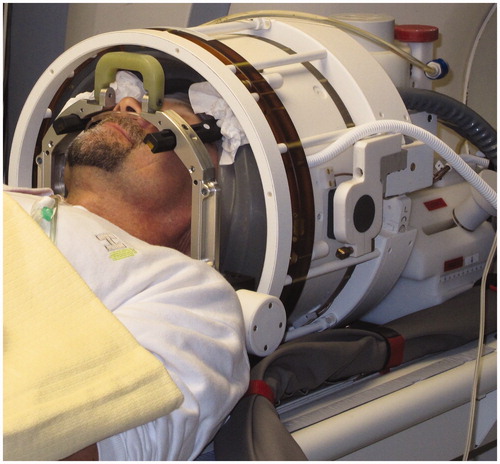
Figure 3. Schematic diagram of a tcFUS treatment with a phased array transducer like the ExAblate® 4000. The patient’s head is fully shaved, fixed to the table with a stereotactic frame and positioned in the helmet-like cavity of the transducer, which is filled with circulating, degassed water for scalp cooling and held back with a flexible membrane seal. The entire system is MR-compatible and integrated into a standard MR system.
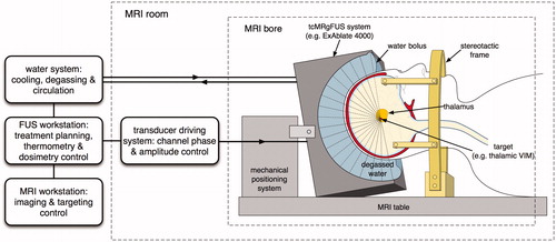
Figure 4. Simulated acoustic pressure distributions from an idealised model of the ExAblate® 4000 system applicator in the presence of a human head model segmented from MR data [Citation77,Citation78] on planes through the location of the geometric focus. (Left) Pressure distribution in the presence of skull-induced aberrations, including shifting and distortion of the focal spot, significant energy deposition on the skull bone and scalp, as well as the potential generation of secondary foci and standing waves. (Right) Pressure distribution after application of a ‘virtual source’ phase-correction approach.
![Figure 4. Simulated acoustic pressure distributions from an idealised model of the ExAblate® 4000 system applicator in the presence of a human head model segmented from MR data [Citation77,Citation78] on planes through the location of the geometric focus. (Left) Pressure distribution in the presence of skull-induced aberrations, including shifting and distortion of the focal spot, significant energy deposition on the skull bone and scalp, as well as the potential generation of secondary foci and standing waves. (Right) Pressure distribution after application of a ‘virtual source’ phase-correction approach.](/cms/asset/be121916-3ac6-4cdf-894c-12257ffc070a/ihyt_a_861519_f0004_b.jpg)
Figure 5. Schematic diagram of the implanted hydrophone correction technique, which is considered the ‘gold standard’ in experimental studies. A hydrophone implanted at the intended target location records the complex pressure for each element of a phased array transducer activated in a sequential manner. The recorded phases are processed and inverted before being applied back to the transducer elements to correct for the skull aberrations and refocus at the target location.
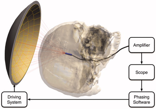
Figure 6. Schematic diagram showing the concept of the ‘virtual source’ correction technique. A point source is placed at the intended target location, here, in the right thalamic ventral intermediate nucleus (VIM). The elements of the phased array transducer are used as receivers, and an ‘inverse propagation’ simulation allows the elements to record the pressure waves as either the entire waveform or the complex pressure phasors. These recorded pressure waves are inverted – either reversed in time for waveforms, or conjugated for complex pressure phasors – and a forward propagation simulation or experiment yields refocusing at the intended target.
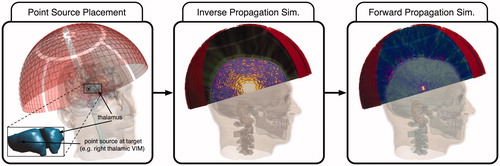
Figure 7. Schematic diagram of a CT-based phase correction approach concept commonly employed in modern tcFUS systems. The patient’s CT scan is entered into the system’s planning software, which segments the skull as a single layer of bone and performs a ray-tracing analysis to calculate the average HU values along the path of the ray for each array element. These HU values are entered into an existing statistical model, based on measurements of ex vivo skulls, to yield an effective speed of sound, which can be used to calculate phase corrections and achieve re-focusing.
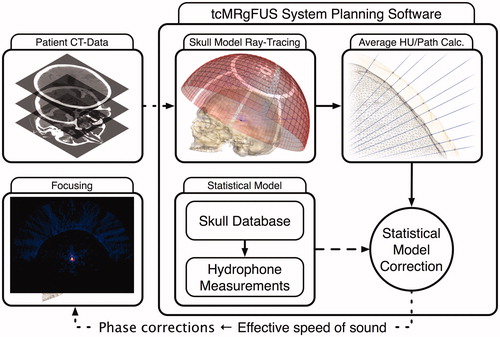
Table 1. A qualitative comparison of the presented approaches.