Figures & data
Table 1. Variability of ablation size with commercial RF electrodes in ex vivo bovine liver [Citation33].
Figure 1. Matrix radiofrequency ablation. The whole tumour volume is contained within a cage of x × y parallel electrodes. The volume within this cage is the sum of (x − 1) × (y − 1) square blocks, each determined by 2 × 2 electrodes. One cluster of 2 × 2 electrodes is the smallest functional unit of such a matrix of electrodes. Ablation of the whole volume is obtained by activation of the 2 × 2 electrodes around the first block, then rapidly switching to the electrodes around the second block, and so on until impedance rise at all blocks prevents further current flow.
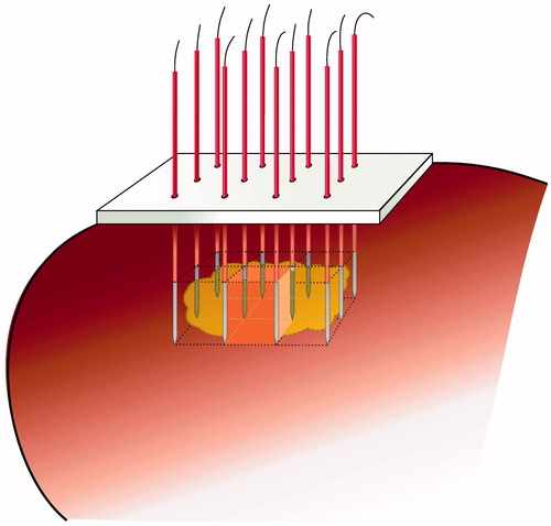
Figure 2. Ex vivo bovine liver experiments. Temperature was monitored with a thermocouple in the centre of the square determined by the tips of the four radiofrequency electrodes.
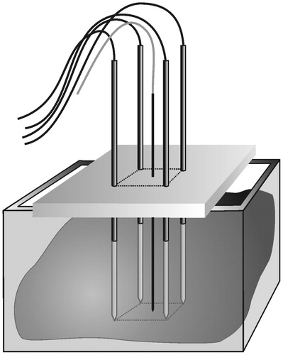
Figure 3. Ex vivo bovine liver experiments: electric wiring scheme. ◯ = electrode; • = thermocouple. (A) standard ‘row’ pattern: the current flows between the first row of two positive electrodes and the second row of two negative electrodes (B) ‘chessboard’ pattern: the current flows between two positive electrodes which are at the opposite corners of the square and two negative electrodes which are at the other two opposite corners of the square.
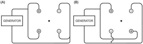
Figure 4. (A) Ex vivo bovine liver experiments: influence of power on current (mean ± SD). (B) Ex vivo bovine liver experiments: influence of power on temperature (mean ± SD) measured in the centre of the square determined by the tips of the four radiofrequency electrodes. (C) Ex vivo bovine liver experiments: influence of power on ablation zone in axial and transverse plane and on mean duration until shut-off.
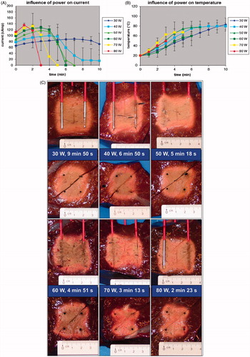
Figure 4. (D) FEM modelling with RAFEM-2: influence of power on temperature distribution in axial and transverse plane at current shut-off.
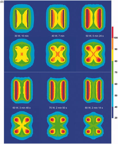
Figure 5. (A) Ex vivo bovine liver experiments: influence of duration on ablation zone in axial and transverse plane (50 W). (B) FEM modelling with RAFEM-2: influence of duration on temperature distribution in axial and transverse plane (50 W). There are no results for 6 and 10 min because power shut-off in the simulation occurred at 5 min 24 s.
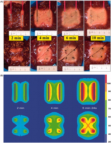
Figure 6. (A) Ex vivo bovine liver experiments: influence of electrode diameter on current. (B) Ex vivo bovine liver experiments: influence of electrode diameter on temperature measured in the centre of the square determined by the tips of the four radiofrequency electrodes. (C) Ex vivo bovine liver experiments: influence of electrode diameter on ablation zone in axial and transverse plane. (D) FEM modelling with ANSYS: influence of electrode diameter on electric field (V/m) at the cross section of the axial and the transverse plane (distances measured from the centre). (E) FEM modelling with ANSYS: influence of electrode diameter on temperature (°C) after 130 s at the cross section of the axial and the transverse plane (distances measured from the centre).
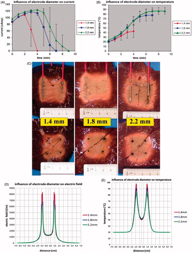
Figure 7. (A) Ex vivo bovine liver experiments: influence of electrode pattern on ablation zone in axial and transverse plane. (B) FEM modelling with RAFEM-2: influence of pattern on electric field (V/m) in axial and transverse plane. (C) FEM modelling with RAFEM-2: influence of pattern on temperature (°C) in axial and transverse plane at current shut-off: 5 min 24 s for row pattern and 3 min 42 s for chessboard pattern.
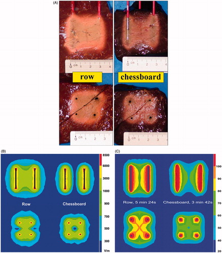
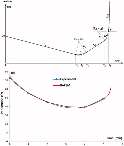
Figure 8. (A) FEM modelling with RAFEM-2: temperature dependent changes in resistivity during the heating phase are described by a line-circle-line-circle exponential function, Equations Equation3–7, using parameters given in . (B) Determination of parameters in Equations Equation3–7 by fitting ex vivo bovine liver impedance data with RAFEM-2 (power = 50 W, distance between electrodes = 2 cm, diameter of electrode = 1.8 mm, row pattern).