Figures & data
Figure 1. Principal membrane curvatures. Schematic presentation of the two principal membrane curvatures C1 and C2 (for the case of saddle-like membrane shape) defined in the origin of the membrane normal n. The principal curvatures C1 and C2 are inversely proportional to principal radii of curvatures R1 and R2, respectively. The principal radii of curvatures R1 and R2 are the maximal and the minimal radii of curvature of the curves defined by the cross-section of the normal plane with the membrane neutral plane.
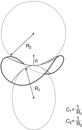
Figure 2. Prolactin vesicles residing at the plasma membrane in resting lactotrophs undergo repetitive transient exocytosis with narrow fusion pores. (a) Confocal image of vesicles containing prolactin visualized by anti-prolactin antibody and fluorescent secondary antibody (Alexa546). Note several bright fluorescent spots at cell perimeter, each likely representing immunolabelled prolactin vesicle at the cell plasma membrane of a resting lactotroph. Scale bar = 5 μm. (b) Representative cell-attached patch-clamp recordings of a resting lactotroph. On- and off-steps in Im traces are taken from a burst. (i) Note that the crosstalk between the Im and Re trace occurs with one event only (arrow). (ii) The crosstalk between Im and Re appears in all but one fusion pore event with higher amplitude (arrow). Calibration pulses (asterisks) do not exhibit projections to the Re trace, thus indicating correct phase angle setting. The crosstalk between the Im and Re traces indicates a narrow fusion pore.
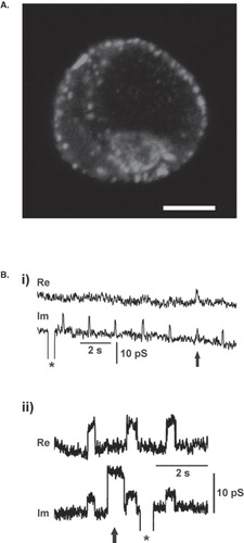
Figure 3. Stable configuration of the fusion pore (vesicle fused to the plasma membrane) as a function of the fusion pore diameter and intrinsic anisotropy of the membrane constituents. (A) The sum of the relative area densities of the anisotropic (type 2) membrane constituents (m2 = m2,1 + m2,2) in both membrane monolayers, shown for three different vesicle shapes (see panel below) of 300 nm in diameter fused to the inner membrane surface. Anisotropic membrane constituents have C1m,2 ≈ 0 and C2m,2 = −1/3 nm−1 which corresponds to Hm,2 = −Dm,2 = −1/6 nm−1. (B) Free energy of the two component bilayer membrane (ΔF) as a function of the fusion pore diameter (Δ) calculated for different values of the intrinsic curvature deviator of the anisotropic (type 2) membrane constituents in the membrane bilayer Hm,2 = −Dm,2: −1/5.75 nm−1 (a), −1/6 nm−1 (b), −1/6.2 nm−1 (c), −1/6.5 nm−1 (d). Arrows show the values of Δ(nm) corresponding to the shapes presented in panel A. (C) The calculated equilibrium fusion/pore diameter (Δeq), corresponding to the minimum of ΔF (see panel B) as a function of the anisotropy Dm,2 = |Hm,2| (see Supplementary Appendix A and Materials and Methods). Note that on the left side of the vertical dotted line, the local minimum of ΔF does not exist (see curve (d) in panel B). Values of the model parameters are: Hm,1 = Dm,1 = 0, K1 = 10 kT nm2 [Citation21,Citation28], K2 = 100 kT nm2, ![]()
![Figure 3. Stable configuration of the fusion pore (vesicle fused to the plasma membrane) as a function of the fusion pore diameter and intrinsic anisotropy of the membrane constituents. (A) The sum of the relative area densities of the anisotropic (type 2) membrane constituents (m2 = m2,1 + m2,2) in both membrane monolayers, shown for three different vesicle shapes (see panel below) of 300 nm in diameter fused to the inner membrane surface. Anisotropic membrane constituents have C1m,2 ≈ 0 and C2m,2 = −1/3 nm−1 which corresponds to Hm,2 = −Dm,2 = −1/6 nm−1. (B) Free energy of the two component bilayer membrane (ΔF) as a function of the fusion pore diameter (Δ) calculated for different values of the intrinsic curvature deviator of the anisotropic (type 2) membrane constituents in the membrane bilayer Hm,2 = −Dm,2: −1/5.75 nm−1 (a), −1/6 nm−1 (b), −1/6.2 nm−1 (c), −1/6.5 nm−1 (d). Arrows show the values of Δ(nm) corresponding to the shapes presented in panel A. (C) The calculated equilibrium fusion/pore diameter (Δeq), corresponding to the minimum of ΔF (see panel B) as a function of the anisotropy Dm,2 = |Hm,2| (see Supplementary Appendix A and Materials and Methods). Note that on the left side of the vertical dotted line, the local minimum of ΔF does not exist (see curve (d) in panel B). Values of the model parameters are: Hm,1 = Dm,1 = 0, K1 = 10 kT nm2 [Citation21,Citation28], K2 = 100 kT nm2, Display full size [Citation68], w = −0.25, z2 = 6, Display full size, m0 = 1.67 nm−2 and R0 = 1000 nm. (D) Schematic representation of the fusion pore with anisotropic constituents in both membrane layers and a fusion pore diameter (Δ) of ∼0.6 nm. The thickness of the membrane layer containing glycolipids (∼ 4 nm) is larger than the thickness of the membrane layer without gylcolipids (∼ 2.5 nm).](/cms/asset/1ecf7aa5-93fa-4b30-85fe-89ef9607754a/imbc_a_460219_f0003_b.jpg)
Figure 4. Properties of vesicle capacitance Cv and fusion pore conductance Gp of transient fusion pore openings in resting lactotrophs. (a) Examples of time-dependent changes of Re and Im traces in resting lactotrophs. Time-dependent changes in Cv indicate that we are observing fusion activity of two dissimilar sized vesicles with different Gp. Events in Im without projections to Re were also observed in the patch (not shown). To calculate Cv and Gp in the right trace, we subtracted the calibration pulse seen in Im. (b) Amplitude distribution of on- and off-steps in Cv with top abscissa showing the vesicle diameter (specific membrane capacitance of 8 fF/μm2 was used). Note, that the average Cv of on-steps (6.1 ± 0.2 fF, n = 749) and the ensuing off-steps (5.7 ± 0.2 fF, n = 749) did not differ significantly (p > 0.05). (c) Frequency distribution of Gp. The average Gp was 36.5 ± 0.9 pS (n = 749). (d) Scatter plot diagram of Gp and Cv (n = 749). Note that vesicles with larger Cv have also larger Gp. Correlation coefficient between the two parameters is significantly different from zero (r = 0.38 ± 0.1, p < 0.0001, n = 749). Dashed lines indicate the limits of detection of signals related to the Gp calculation [Citation37].
![Figure 4. Properties of vesicle capacitance Cv and fusion pore conductance Gp of transient fusion pore openings in resting lactotrophs. (a) Examples of time-dependent changes of Re and Im traces in resting lactotrophs. Time-dependent changes in Cv indicate that we are observing fusion activity of two dissimilar sized vesicles with different Gp. Events in Im without projections to Re were also observed in the patch (not shown). To calculate Cv and Gp in the right trace, we subtracted the calibration pulse seen in Im. (b) Amplitude distribution of on- and off-steps in Cv with top abscissa showing the vesicle diameter (specific membrane capacitance of 8 fF/μm2 was used). Note, that the average Cv of on-steps (6.1 ± 0.2 fF, n = 749) and the ensuing off-steps (5.7 ± 0.2 fF, n = 749) did not differ significantly (p > 0.05). (c) Frequency distribution of Gp. The average Gp was 36.5 ± 0.9 pS (n = 749). (d) Scatter plot diagram of Gp and Cv (n = 749). Note that vesicles with larger Cv have also larger Gp. Correlation coefficient between the two parameters is significantly different from zero (r = 0.38 ± 0.1, p < 0.0001, n = 749). Dashed lines indicate the limits of detection of signals related to the Gp calculation [Citation37].](/cms/asset/508a5216-2d5b-49e0-bb95-82f264071977/imbc_a_460219_f0004_b.jpg)
Figure 5. Relationship between the vesicle and the fusion pore diameters. The fusion pore diameter, estimated from fusion pore conductance Gp, is plotted as a function of the vesicle diameter (2 Rv). Vesicle diameter was estimated from the vesicle capacitance Cv, by assuming spherical shape of vesicles. Filled symbols denote experimental data; line denotes the curve Δeq = Δ0e−κ/(RV + B) (see Eq. (Citation7)) where we determined parameters Δ0 = 16.6 nm, κ = 2641.5 nm and B = 550.7 nm by using the least squares method to fit the experimental points.
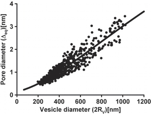
Figure 6. Stages vesicles undergo to accomplish the regulated release of chemical messengers. Fusion of vesicle and the plasma membrane represents the key event in regulated release of neurotransmitters and hormones. This process is thought to begin with the formation of a hemi-fusion stalk (transition A), an intermediate structure connecting the outer leaflets of fusing membranes (reviewed in [Citation3]). The hemi-fusion stalk then proceeds into a fusion pore (transition B), an aqueous channel connecting a spherical vesicle and the nearly ‘flat’ plasma membrane, through which cargo molecules diffuse from the vesicle lumen into the cell exterior. Fusion pore can reversibly vary its diameter (transitions C). The results of this paper show that fusion pores exhibit stability, which is depicted in the reaction diagram (bottom right). During the intermediate state (C), which is energetically stable, the fusion pore diameter may be too narrow to permeate luminal cargo molecules and therefore this state could be considered release incompetent [Citation7,Citation8]. Following the delivery of a stimulus, vesicles in state C may transit into a state with a wider fusion pore diameter, leading into a state of full fusion.
![Figure 6. Stages vesicles undergo to accomplish the regulated release of chemical messengers. Fusion of vesicle and the plasma membrane represents the key event in regulated release of neurotransmitters and hormones. This process is thought to begin with the formation of a hemi-fusion stalk (transition A), an intermediate structure connecting the outer leaflets of fusing membranes (reviewed in [Citation3]). The hemi-fusion stalk then proceeds into a fusion pore (transition B), an aqueous channel connecting a spherical vesicle and the nearly ‘flat’ plasma membrane, through which cargo molecules diffuse from the vesicle lumen into the cell exterior. Fusion pore can reversibly vary its diameter (transitions C). The results of this paper show that fusion pores exhibit stability, which is depicted in the reaction diagram (bottom right). During the intermediate state (C), which is energetically stable, the fusion pore diameter may be too narrow to permeate luminal cargo molecules and therefore this state could be considered release incompetent [Citation7,Citation8]. Following the delivery of a stimulus, vesicles in state C may transit into a state with a wider fusion pore diameter, leading into a state of full fusion.](/cms/asset/7d1accb2-b2f7-425c-b3d1-767b5915812d/imbc_a_460219_f0006_b.jpg)