Figures & data
Figure 1. The coordinate systems and the transformations relating them to each other.
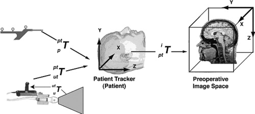
Figure 2. 3D composite ultrasound volume: MRI in grey with US overlaid in a hot-metal color scale. (a) axial view; (b) sagittal view; (c) coronal view.
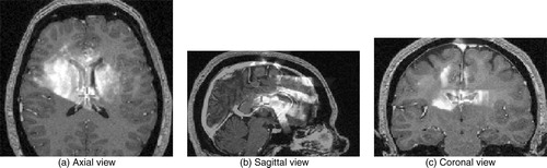
Figure 3. Generating pseudo US. The original MRI is segmented using ANIMAL, a radial gradient is then applied, and these are merged to create a pseudo US image. a) original MRI; b) segmented MRI; c) gradient MRI; d) pseudo US.
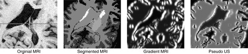
Table I. Intensity mappings for the pseudo US depicted in .
Figure 4. Flowchart of the non-linear registration system.
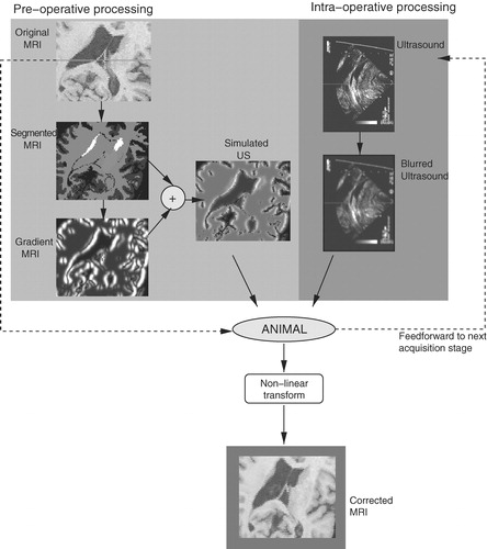
Figure 5. Operating room floor plan. The experimental US-MRI IGNS system is used in conjunction with a standard commercial IGNS reference system (SNN, Cedera, Toronto, Canada).
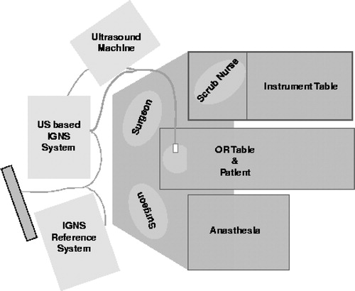
Figure 6. Left selective amygdalo-hippocampectomy for intractable epilepsy: zoom of transverse images through the lateral ventricles. Patient was in the supine position with the head turned on the right side. A slight brain deformation is visible before the dura opening (column 2). A larger gravitational displacement (towards the right of the image) of the median structures is observed after dura opening (column 3). The deformation mainly involves the anterior horn of the left lateral ventricle (white arrow), whereas the falx (arrowhead) and septum pellucidum (double arrowhead) do not move. Correction of the deformation is demonstrated during these two surgical steps.
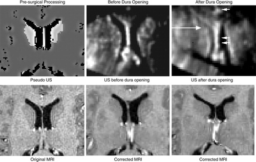
Figure 7. Case from illustrating US (in green) after dura opening over original MRI (left) and over corrected MRI (right). Notice the distinct collapse of the left lateral ventricle.
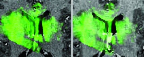
Figure 8. Case with right frontal recurrent malignant tumor. Left: intra-operative MRI; center: intra-operative US; right: corrected MRI. These near-transverse images show the tumor (top) and ventricles (bottom), with the front of the head towards the right. After dura opening, the sinking of the entire tumor, as well as the deeply-seated median structures, are clearly visible as a displacement towards the bottom of the image. The MRI is corrected for deformations of both pathological and anatomical structures (e.g., the ventricle is displaced and slightly compressed; the tumor is also displaced). The posterior part of the septum drops, but the anterior part does not as the registration system confuses it with the choroid plexus. This will be fixed with proper representation of the septum and choroid plexus in the simulations. Note that the falx does not move.
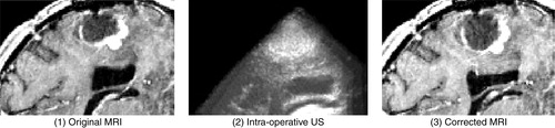
Figure 9. Tumor case. The ultrasound images acquired at various stages in the procedure are displayed in green overlaid onto the original MRI (left column) and onto the corrected MRI (right column). The images were acquired as follows: (a) on the dura surface; (b) on the cortex after the opening of the dura; and (c) at the end of the procedure. These transverse images depict the tumor in black. Notice that the corrected MRIs (on the right) depict more closely the surgical reality as reflected by the US images than do the original MRIs. This is particularly evident at the end of the procedure when the tumor has been resected, and was no longer visible in the US image. The final corrected MRI accurately reflects the absence of the tumor.
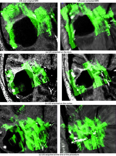
Table II. Quantification of registration error before and after correction for non-linear brain deformations. The table depicts the average distance in mm between key anatomical structures or pathologies visible in the US and MR images for the cases described. The results before and after correction for brain deformations are shown for the states prior to and after the dura was opened. Note that in the case of , no data was acquired on the dura.