574
Views
1
CrossRef citations to date
0
Altmetric
Research Article

Accuracy of navigation in hip resurfacing with different surgeons and varying anatomy

, MD, , , , , & show all
Pages 77-85 | Received 26 Jan 2011, Accepted 15 Dec 2011, Published online: 20 Feb 2012

Figures & data

Figure 1. The set of 8 different femurs, including 5 femurs with normal anatomy and 3 with abnormal anatomy. The abnormal femurs comprise one with a pistol grip deformity after slipped epiphysis (3rd from left), one with valgus deformity (6th from left), and one with a severely arthritic head (8th from left).
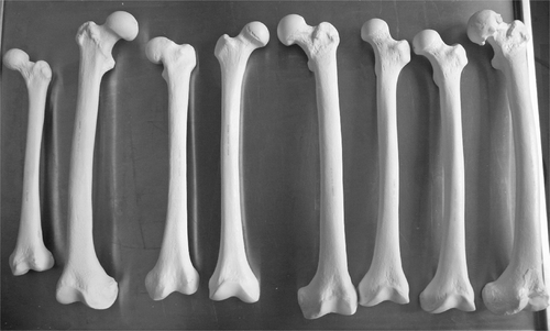
Figure 1. The set of 8 different femurs, including 5 femurs with normal anatomy and 3 with abnormal anatomy. The abnormal femurs comprise one with a pistol grip deformity after slipped epiphysis (3rd from left), one with valgus deformity (6th from left), and one with a severely arthritic head (8th from left).

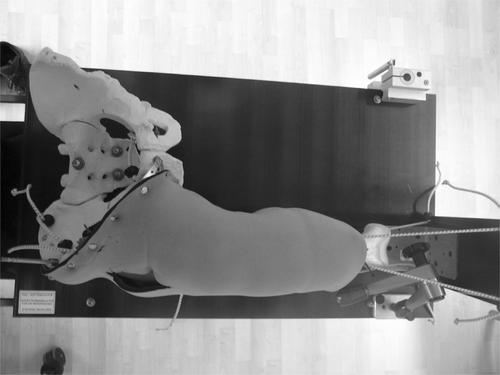
Figure 2. Ventral view of hip simulator with hip joint reduced.

Figure 2. Ventral view of hip simulator with hip joint reduced.

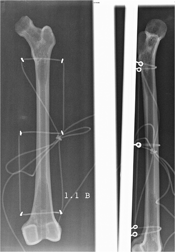
Figure 3. Radiographs of the femur showing anterior-posterior and lateral views.

Figure 3. Radiographs of the femur showing anterior-posterior and lateral views.

Table I.  Mean results, standard deviation, range and p-values for comparison of conventional and navigated method. Significant differences are in highlighted in bold.

Figure 4. CCD angle in conventional and navigated implantation for all surgeons. The box is defined by the upper and lower quartiles and the whiskers contain 95% of the observations. The dark line in the box is the median; data represented by black dots are outliers.
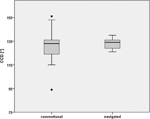
Figure 4. CCD angle in conventional and navigated implantation for all surgeons. The box is defined by the upper and lower quartiles and the whiskers contain 95% of the observations. The dark line in the box is the median; data represented by black dots are outliers.
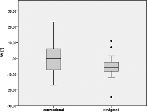
Figure 5. AV angle in conventional and navigated implantation for all surgeons. The box is defined by the upper and lower quartiles and the whiskers contain 95% of the observations. The dark line in the box is the median; data represented by black dots are outliers.

Figure 5. AV angle in conventional and navigated implantation for all surgeons. The box is defined by the upper and lower quartiles and the whiskers contain 95% of the observations. The dark line in the box is the median; data represented by black dots are outliers.

Figure 6. CCD angle for the three different surgeons with conventional and navigated implantation. The box is defined by the upper and lower quartiles and the whiskers contain 95% of the observations. The dark line in the box is the median.
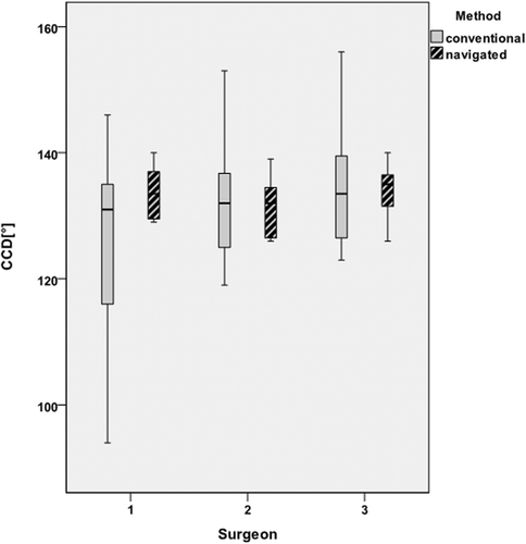
Figure 6. CCD angle for the three different surgeons with conventional and navigated implantation. The box is defined by the upper and lower quartiles and the whiskers contain 95% of the observations. The dark line in the box is the median.

Figure 7. AV angle for the three different surgeons with conventional and navigated implantation. The box is defined by the upper and lower quartiles and the whiskers contain 95% of the observations. The dark line in the box is the median; data represented by black dots are outliers.
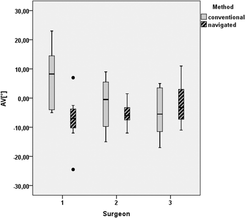
Figure 7. AV angle for the three different surgeons with conventional and navigated implantation. The box is defined by the upper and lower quartiles and the whiskers contain 95% of the observations. The dark line in the box is the median; data represented by black dots are outliers.

Table II.  Mean results, standard deviation, range and p-values for comparison among the three different surgeons for both methods. Significant differences are highlighted in bold.

Table III.  Mean results, standard deviation, range and p-values for comparison between abnormal and abnormal anatomy for both methods. Significant differences are highlighted in bold.
Reprints and Corporate Permissions

Please note: Selecting permissions does not provide access to the full text of the article, please see our help page How do I view content?

To request a reprint or corporate permissions for this article, please click on the relevant link below:

Academic Permissions

Please note: Selecting permissions does not provide access to the full text of the article, please see our help page How do I view content?

Obtain permissions instantly via Rightslink by clicking on the button below:

If you are unable to obtain permissions via Rightslink, please complete and submit this Permissions form. For more information, please visit our Permissions help page.