821
Views
11
CrossRef citations to date
0
Altmetric
Research Article

Application of a CT-3D fluoroscopy matching navigation system to the pelvic and femoral regions

, MD, PhD, , &
Pages 69-76 | Received 14 Jul 2011, Accepted 07 Dec 2011, Published online: 20 Feb 2012

Figures & data

Figure 1. The dry human pelvis and femur with 16 fiducial markers, each consisting of a metal ball 1.5 mm in diameter. Four markers were fixed to the acetabulum: one to each of its anterior (1), posterior (2), superior (3), and inferior edges (4). Four markers were fixed to the peripheral region of the pelvis, one to each of the following sites: the anterior superior iliac spine (5), pubic tubercle (6), sciatic notch (7), and ischial tuberosity (8). Four markers were fixed to the femoral head and neck, one at each of the following locations: the superior (9), anterior (10), and inferior head-neck junctions (11), and the anterior cortex of the femoral neck (12). Finally, four markers were fixed to the proximal femur, one to each of the following sites: the tip of the great trochanter (13), the base of the lesser trochanter (14), and the anterior (15) and lateral sides of the femoral shaft (16).
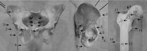
Figure 1. The dry human pelvis and femur with 16 fiducial markers, each consisting of a metal ball 1.5 mm in diameter. Four markers were fixed to the acetabulum: one to each of its anterior (1), posterior (2), superior (3), and inferior edges (4). Four markers were fixed to the peripheral region of the pelvis, one to each of the following sites: the anterior superior iliac spine (5), pubic tubercle (6), sciatic notch (7), and ischial tuberosity (8). Four markers were fixed to the femoral head and neck, one at each of the following locations: the superior (9), anterior (10), and inferior head-neck junctions (11), and the anterior cortex of the femoral neck (12). Finally, four markers were fixed to the proximal femur, one to each of the following sites: the tip of the great trochanter (13), the base of the lesser trochanter (14), and the anterior (15) and lateral sides of the femoral shaft (16).

Figure 2. Experimental set-up for the dry bone study. The C-arm was placed on the left side of the operating table, and the navigation system at the caudal end of the table. Surgery around the hip joint was simulated with a dry human pelvis and femur placed on the operating table in the lateral decubitus position.
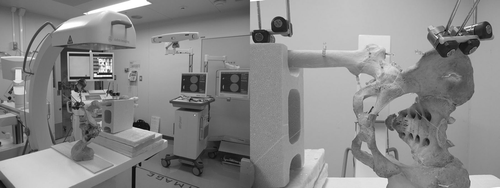
Figure 2. Experimental set-up for the dry bone study. The C-arm was placed on the left side of the operating table, and the navigation system at the caudal end of the table. Surgery around the hip joint was simulated with a dry human pelvis and femur placed on the operating table in the lateral decubitus position.

Figure 3. Left Fluoroscopic imaging centers of the pelvis for CT-3D fluoroscopy matching were the pubic symphysis (a), the acetabular fossa (b), and a site on the ilium 3 cm above the acetabular roof (c) (the imaging centers are indicated with crosshairs). Right: Fluoroscopic imaging centers of the proximal femur for CT-3D fluoroscopy matching were the base of the femoral neck (d), the femoral shaft at the level of the lesser trochanter (e), and the inferior border of the great trochanter (f).
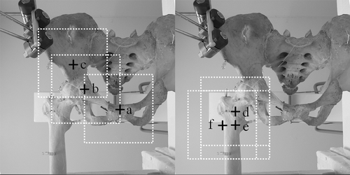
Figure 3. Left Fluoroscopic imaging centers of the pelvis for CT-3D fluoroscopy matching were the pubic symphysis (a), the acetabular fossa (b), and a site on the ilium 3 cm above the acetabular roof (c) (the imaging centers are indicated with crosshairs). Right: Fluoroscopic imaging centers of the proximal femur for CT-3D fluoroscopy matching were the base of the femoral neck (d), the femoral shaft at the level of the lesser trochanter (e), and the inferior border of the great trochanter (f).

Figure 4. Upper row: Two-dimensional fluoroscopic images of the pelvis with the imaging center on the pubic symphysis (a), the acetabular fossa (b), and a site on the ilium 3 cm above the acetabular roof (c). Lower row: Two-dimensional fluoroscopic images of the proximal femur with the imaging center on the base of the femoral neck (d), the femoral shaft at the level of the lesser trochanter (e), and the inferior border of the great trochanter (f). The fluoroscopic imaging centers are indicated with crosshairs.
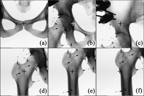
Figure 4. Upper row: Two-dimensional fluoroscopic images of the pelvis with the imaging center on the pubic symphysis (a), the acetabular fossa (b), and a site on the ilium 3 cm above the acetabular roof (c). Lower row: Two-dimensional fluoroscopic images of the proximal femur with the imaging center on the base of the femoral neck (d), the femoral shaft at the level of the lesser trochanter (e), and the inferior border of the great trochanter (f). The fluoroscopic imaging centers are indicated with crosshairs.

Figure 5. The navigation display showing multiplanar reconstructed views of CT images. The tip of the navigation probe was directed at each marker, and the TRE was measured as the distance between the virtual tip of the navigation probe and the marker on the navigation display.
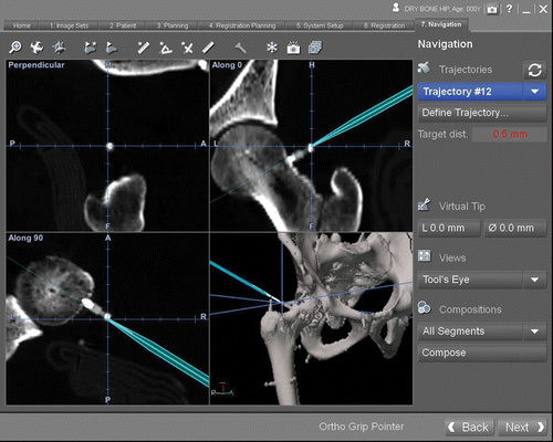
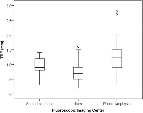
Figure 5. The navigation display showing multiplanar reconstructed views of CT images. The tip of the navigation probe was directed at each marker, and the TRE was measured as the distance between the virtual tip of the navigation probe and the marker on the navigation display.
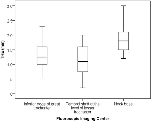
Figure 6. Box-whisker plots showing target registration error over the pelvis for each fluoroscopic imaging center. There were significant differences in TRE among the imaging centers.

Figure 6. Box-whisker plots showing target registration error over the pelvis for each fluoroscopic imaging center. There were significant differences in TRE among the imaging centers.

Figure 7. Box-whisker plots showing target registration error over the proximal femur for each fluoroscopic imaging center. There were significant differences in TRE among the imaging centers.

Figure 7. Box-whisker plots showing target registration error over the proximal femur for each fluoroscopic imaging center. There were significant differences in TRE among the imaging centers.

Reprints and Corporate Permissions

Please note: Selecting permissions does not provide access to the full text of the article, please see our help page How do I view content?

To request a reprint or corporate permissions for this article, please click on the relevant link below:

Academic Permissions

Please note: Selecting permissions does not provide access to the full text of the article, please see our help page How do I view content?

Obtain permissions instantly via Rightslink by clicking on the button below:

If you are unable to obtain permissions via Rightslink, please complete and submit this Permissions form. For more information, please visit our Permissions help page.