Figures & data
Figure 1. Delta CTA prosthesis build in the average anatomical model based on 200 measured scapulae, with specific interest in the shape of the glenoid cavity, the infraglenoid tubercle, and the lateral border of the scapula. The prosthesis has a flat baseplate situated as distally as possible to ensure full bony coverage of this baseplate with the inferior screw surrounded by minimum 2 mm bone, and a glenosphere 36 mm with a standard polyethylene cup. The notch angand le is the maximum adduction angle before a conflict arises between the PE cup and scapular pillar.
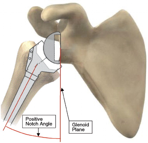
Figure 2. The parameters studied: 1. change in the angle of the humeral neck shaft inclination; 2. change in the depth of the polyethylene cup; 3. lateralization of the center of rotation; 4. downward glenoid inclination; 5. increase in glenosphere radius; 6. creation of an inferior prosthetic overlap with the glenoid bone.
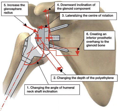
Figure 3. Influence of neck-shaft inclination on the notch angle. (Simulation of maximal adduction in average scapular morphology and in worse-case scapular anatomy: no horizontal pillar. Images of average scapular morphology).
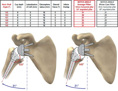
Figure 4. Influence of reduction of cup depth on the notch angle. (Simulation of maximal adduction in average scapular morphology and in worse-case scapular anatomy: no horizontal pillar. Images of average scapular morphology).
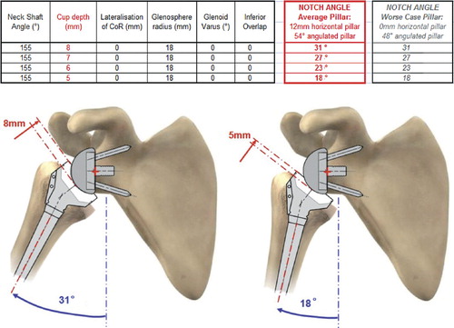
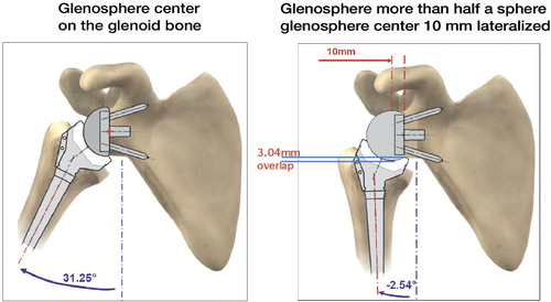
Figure 5. Influence of lateralization on the notch angle. 2 cases with or without inferior overhang. (Simulation of maximal adduction in average scapular morphology and in worse-case scapular anatomy: no horizontal pillar. Images of average scapular morphology).
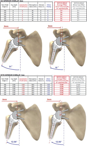
Figure 6. Influence of downward glenoid inclination on the notch angle (called “glenoid varus” in the spreadsheet). (Simulation of maximal adduction in average scapular morphology and in worse-case scapular anatomy: no horizontal pillar. Images of average scapular morphology).
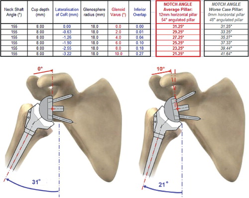
Figure 7. Influence of glenosphere radius on notch angle. (Simulation of maximal adduction in average scapular morphology and in worse-case scapular anatomy: no horizontal pillar. Images of average scapular morphology).
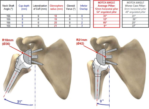
Figure 8. influence of inferior prosthetic overhang on the notch angle. (Simulation of maximal adduction in average scapular morphology and in worse-case scapular anatomy: no horizontal pillar. Images of average scapular morphology).
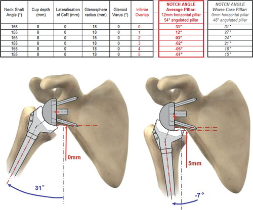
Figure 9. Exponential relationship between the inferior prosthetic overhang and the notch angle.
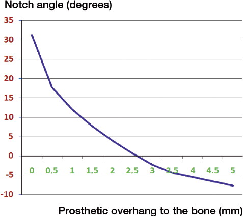
Figure 10. Explanation of the dilemma of Gutiérrez: a prosthetic overhang can also be created by the prosthesis if the center of rotation is lateralized and if the glenosphere is more than half a sphere.