Figures & data
Table 1. Demographic data a
Figure 1 Definition of TAL and TAL-guided cup placement. Step 1: The opening plane (OP), which was fitted to the opening plane of the acetabulum, was settled. This plane contained two lines. A. The first line (white line on the coronal plane) was drawn from the tear drop to the upper acetabular rim edge at the level of the femoral head center. The second line (white line on the axial plane) was drawn from the anterior edge to the posterior edge of acetabular rim at the level of the femoral head center. B. The OP was rotated to be parallel with the y-axis in the coronal plane and parallel with the z-axis in the axial plane. C. The acetabular notch (AN) was identified at the inferior acetabulum. Step 2: The TAL (the black line) was defined as the AP line between the anteroinferior edge; point A and posteroinferior edge; point P of the acetabular rim in the craniocaudal view (D) and lateral view (E). F. Intersection; point R of acetabular rim edge with the vertical plane containing the TAL was settled in the anteroposterior view of the TAL. Line RM, the guide for cup inclination, was drawn from the TAL midpoint M to point R. The TAL plane containing lines AP and RM was settled. G. 3D image of the TAL and the TAL plane. Step 3: The equatorial plane of the cup was virtually placed so as to be parallel with line AP in the craniocaudal view (H), lateral view (I), and line RM in the anteroposterior view (J). K. 3D image of the cup placement. Step 4: Anatomical anteversion of the TAL in the ACS and the FCS and radiographic cup orientation guided by the TAL in the ACS and the FCS was measured in the axial view (L) and the coronal view (M).
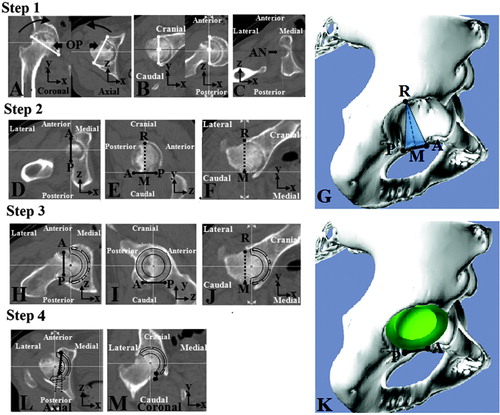
Figure 2. Verification of the TAL alignment measurement method. We verified the measurement method using cadaveric hips. A. The TAL and acetabulum were exposed. B. The beads were attached at the anterior and posterior insertion of the TAL. C. CT images before and after attachment of the beads on the posteroinferior and anteroinferior edges of the acetabular rim were obtained. We compared the anteversion of the line between the bony points on the first CT and the line between the beads on the second CT.
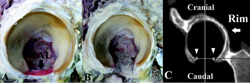
Table 2. Anatomical anteversion of the TAL a
Table 3. Sex differences in anatomical TAL anteversion, measured in degrees a
Table 4. Radiographic definition of TAL-guided cup orientation, measured in degrees a
Figure 3. Scatter diagram of cup orientation measurements in the ACS and FCS. In the ACS, 78 of 80 OA hips (98%) and 49 of 80 ON hips (61%) had a more than 10° difference from our target cup orientation (dotted line area). In the FCS, 78 of 80 OA hips (98%) and 45 of 80 ON hips (56%) had a more than 10° difference from the target cup orientation.
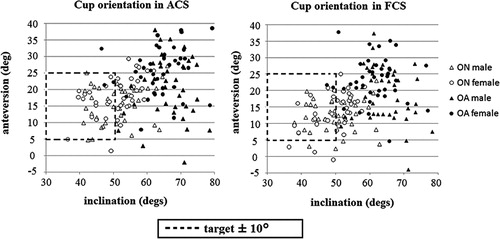
Table 5. Comparison of availability of TAL in THA