Figures & data
Figure 1. On the left part of the figure is shown the appearance of the staple marker in the Neer II prosthesis on two different views of a reconstructed scapula (a). The middle part of the figure shows the reference points outlining marker and scapula (b). On the right part of the figure is shown the reconstructed glenoid and the straight line shape of the metallic marker of the Ulys Ceraver prosthesis with reference points indicated on the marker as well as on the subchondral bone of the glenoid rim (c). StS: staple-shaped marker in the Neer II prosthesis; SLS: straight line marker in the Ulys prosthesis; LBL: lateral border line of the scapula; SFL: supraspinous fossa line; OEP: rim of the subchondral bone of the rim.
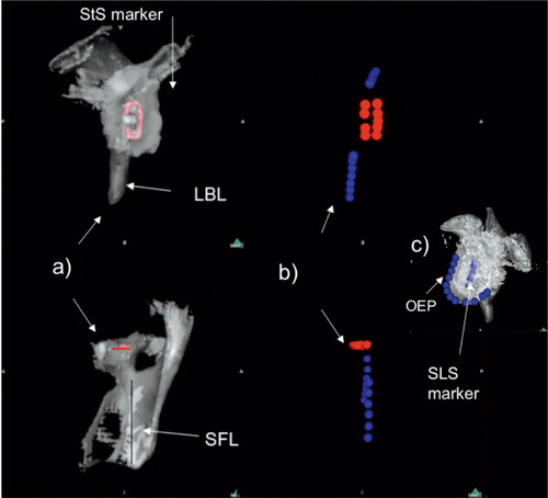
Figure 2. Glenoid and scapula reference points imported into 3D- Reshaper software. Glenoid-related descriptors are marked in red and scapula blade descriptors are marked in blue. On the left is shown the postoperative glenoid implant staple shape marker relative to the scapula plane (SbP). On the right is shown the preoperative eroded glenoid outer edge relative to the scapula plane. GP: glenoid plane; AG: glenoid supero-inferior axis; CG: central point of the glenoid; pCG: orthogonal projection of the central point of the glenoid on the scapula blade plane; Psj: intersecting line between scapula blade plane and glenoid plane.
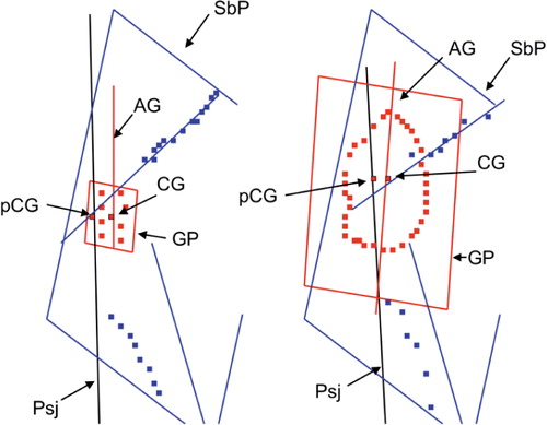
Figure 3. The four position parameters (version, inclination, rotation, and antero-posterior offset distance) are illustrated graphically. Calculated glenoid orientation is shown in red and scapula blade orientation is shown in blue.
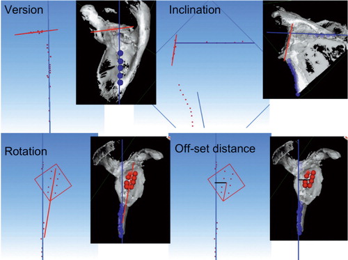
Figure 4. Axial CT views passing through the middle of the glenoid of 3 implants. On the left is shown the implant keel centrally positioned into the glenoid vault (a). In the middle is shown contact between the glenoid keel and the anterior glenoid wall (b). On the right is shown the glenoid keel perforating the anterior glenoid wall (c).
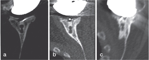
Figure 5. Preoperative axial view of the posteriorly eroded glenoid (left) and postoperative axial view of the same specimen with an implant (right). The orientation of the glenoid vault is indicated by the dotted line. The orientation of the eroded glenoid is indicated by the black line on the left part of the figure. The orientation of the glenoid implant is indicated by the white line on the right part part of the figure. The white arrow indicates anterior perforation of the glenoid vault due to the retroverted orientation of the implant in this preoperatively eroded glenoid.
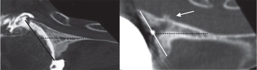
Table 1. Preoperative, postoperative, and correction values for each of the 4 positioning parameters (mean (SD) [range]). Correction was defined as postoperative version subtracted from preoperative version. Retroversion was defined as positive and anteversion negative; superior inclination was positive and inferior inclination negative; clockwise rotation was positive for a right shoulder and anticlockwise rotation was positive for a left shoulder; offset distance was always anterior to the scapular plane
Table 2. Preoperative version of the eroded glenoids (mean (SD)), postoperative version of the glenoid implants, and correction categorized according to preoperative erosion types using the classification system of Walch et al. (Citation1999). Change of version was defined as postoperative version subtracted from preoperative version
Table 3. Degree of implant perforation of the glenoid vault related to postoperative implant position (mean (SD)). “n” is the number of cases. The contact between the keel and cortex in row 3 did not cause perforation of the anterior cortex
Table 4. Preoperative erosion as defined by Walch et al. (Citation1998) related to degree of implant perforation of the glenoid vault. The contact between the keel and cortex in column 4 did not cause perforation of the anterior cortex