Figures & data
Figure 1. Femoral lengthening with a retrograde intramedullary nail (nail group: pair 6).
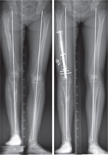
Figure 2. Intraoperative radiographs performed with the image intensifier. a. Reaming of the distal fragment according to the preoperative planning and placement of a blocking screw to allow for controlled axis correction after the osteotomy. b. Percutaneous osteotomy with a drill and osteotome. c. Angulation of the distal fragment and advancement of the straight and rigid reamers into the proximal fragment.
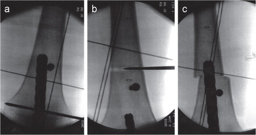
Figure 3. A patient in the nail group (pair 7). Preoperative deformity parameters included shortening and a slightly valgus deformity. Lengthening along the anatomical axis would have increased the valgus deformity. Intraoperative varisation was necessary for axis correction and to achieve a perfect mechanical axis after lengthening was completed.
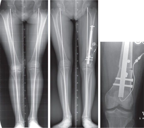
Figure 4. AP and lateral radiograph when lengthening was completed (panels a and b) and 6 weeks later (panels c and d) (nail group: pair 3).
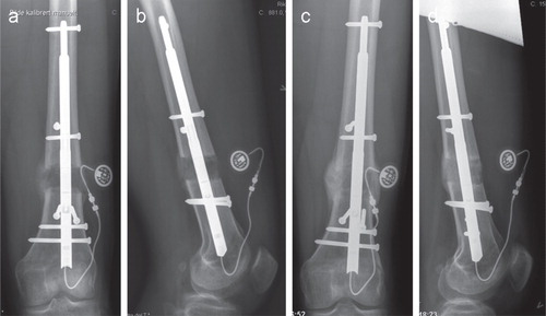
Table 1. Patient data for the 15 matched pairs
Table 2. Deformity parameters preoperatively and at the latest follow-up for both groups
Figure 5. A patient with a biplanar deformity (shortening and valgus) after physeal injury (fixator group: pair 10), which was corrected with the Taylor Spatial Frame.
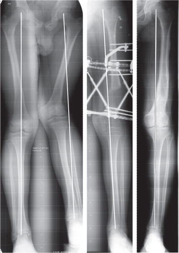
Figure 6. A patient in the nail group (pair 15) with postraumatic deformity including shortening and procurvatum.
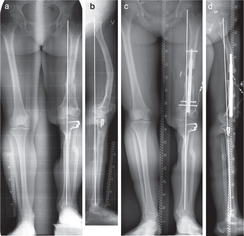
Figure 7. A patient with complex deformity after physeal injury (fixator group: pair 11). Initial deformity parameters included shortening, valgus and recurvatum deformity in the femur. The radiographs from latest follow-up (far right) show some overcorrection into varus deformity on the affected side.
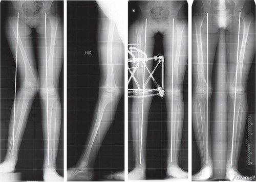
Figure 8. A patient in the nail group (pair 4) with a relatively spacious femoral canal. Procurvatum deformity occurred throughout the course of lengthening. The proximal fragment rotated at the plane of the single proximal locking screw. Blocking screws in the proximal fragment in the frontal plane should have been placed to avoid this angulation.
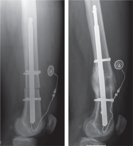
Table 3. Knee joint motion: before, during, and after lengthening.
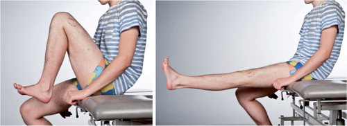
Figure 9. A patient in the nail group (pair 8) demonstrating active ROM in the knee 6 weeks after lengthening was completed.