Figures & data
Figure 1. Schematic diagram of a fringe pattern generator using PANDA ring resonator, where Es: optical fields, Ks: coupling coefficients, Rs: ring radii.
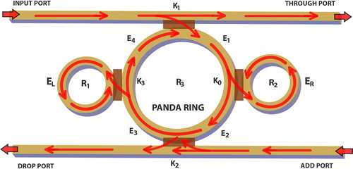
Figure 2. Shows the simulation results, where (a) fringe pattern of through port generated by a PANDA ring circuit(R3 = 1.765 μm) and (b) fringe pattern counting method.
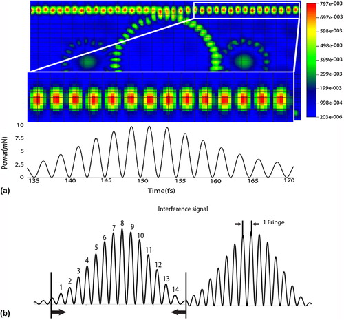
Figure 3. Shows the simulation results of fringe patterns generated by a PANDA ring circuit, where (a) R3 = 1.365 μm, (b) R3 = 1.465 μm, (c) R3 = 1.565 μm, (d) R3 = 1.665 μm, and (e) comparison of signals.
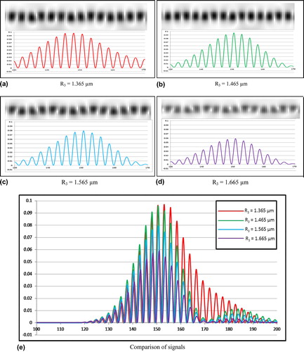
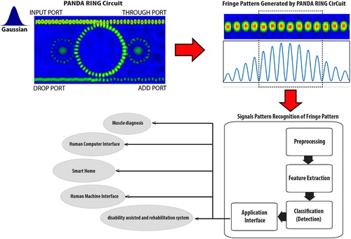
Figure 4. Shows the schematic diagram of fringe pattern generation and interpretation using the proposed design system, where the ring radii varied from 1.365 to 1.665 μm.