Figures & data
Figure 1. Schematic diagram of 3D image transmission system using ring conjugate mirror connected by a transmitter (antenna), where Ei: optical fields, ki: coupling coefficients, Ein: input port (field), Eth: through port, Edrop: drop port, Eadd: add port, Lx: length in μm.
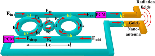
Figure 2. Schematic of WGM switching signals, where (a) 3D whispering gallery mode of light within a 3CR (3 cascaded rings (3CR) waveguide, (b) the switching signals (up or down) can be controlled using the modulated signal input.
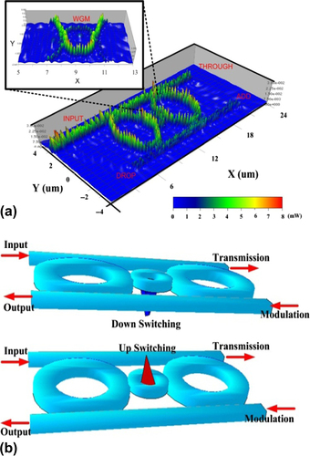
Figure 3. Simulation results of two-dimensional plot and nicely demonstrates the phase conjugate normalized intensities (center ring results) from top are 30, 32, 33 and 36 fs (10 − 15 s), in which different switching directions are applied (red: peaks and blue: valleys).
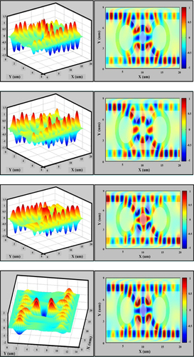
Figure 4. Shows the two-dimensional plot and nicely demonstrates the phase conjugate intensity and wavelength in arbitrary units.
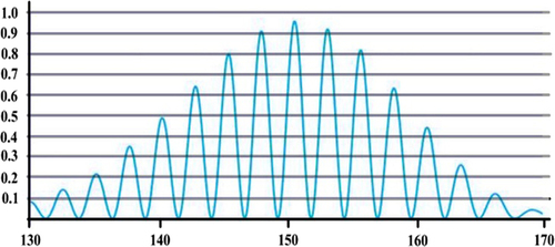
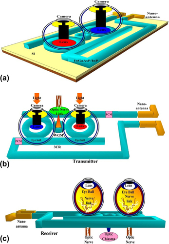
Figure 5. An implanted optical 3CR chip design system for a remote artificial eye system, where (a) image construction, (b) transmitter, (c) receiver, optic nerve and optic chiasm connection.