Figures & data
Figure 1. Schematic of multi-wavelength optical spins generated by soliton pulse in a PANDA ring resonator.
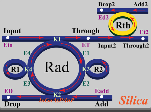
Figure 2. Many soliton spins within a PANDA ring are generated using a dark-soliton pump input at center wavelength 1400, 1425, 1450, 1475, 1500, 1525, 1550, 1575, and 1600 nm.
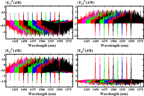
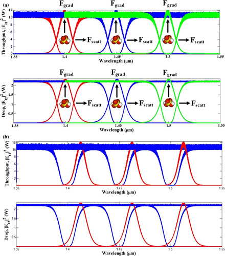
Figure 3. A set of spins obtained at (a) Through port (spin up) and (b) Drop ports (spin down).
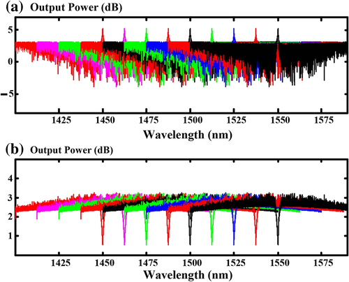
Table I. List of waveguide and system parameters.
Figure 4. (a) 3D drawing of ring laterally gold coupled to the straight waveguides (b) and cross section of add-drop.
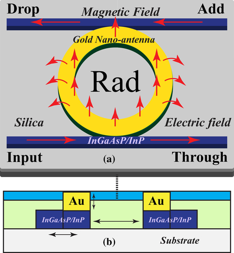
Figure 5. A set of spins obtained at Through and Drop ports of the Rth Add-Drop (CitationYupapin et al. 2013).
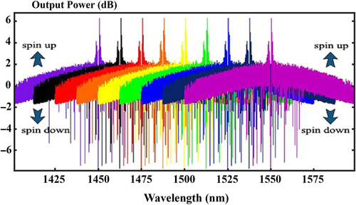
Figure 6. A schematic diagram of spin distributed networks using the multi-wavelength optical spins, where D1: detectors, PBS: polarizing beamsplitter, Rgs: output ring radii (users).
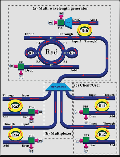
Figure 7. Results received by each user (1–4) from add-drop filter at Through port.
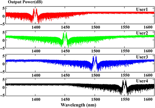
Figure 8. Results received by each user (1–4) from add-drop filter at Drop port.
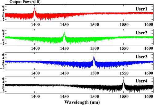
Figure 9. Simulated transmission FSR = 25 nm and FWHM = 4 nm.
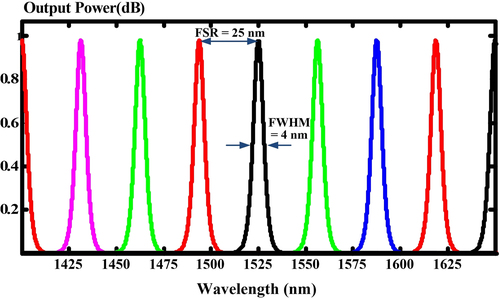
Figure 10. Schematic of trapped molecules within the optical capsules, (a) optical capsules, (b) open optical capsules; Fgrad: gradient force, Fscatt: scattering force.