
Abstract
Background: Magnetic nanoparticle hyperthermia therapy is a promising technology for cancer treatment, involving delivering magnetic nanoparticles (MNPs) into tumours then activating them using an alternating magnetic field (AMF). The system produces not only a magnetic field, but also an electric field which penetrates normal tissue and induces eddy currents, resulting in unwanted heating of normal tissues. Magnitude of the eddy current depends, in part, on the AMF source and the size of the tissue exposed to the field. The majority of in vivo MNP hyperthermia therapy studies have been performed in small animals, which, due to the spatial distribution of the AMF relative to the size of the animals, do not reveal the potential toxicity of eddy current heating in larger tissues. This has posed a non-trivial challenge for researchers attempting to scale up to clinically relevant volumes of tissue. There is a relative dearth of studies focused on decreasing the maximum temperature resulting from eddy current heating to increase therapeutic ratio.
Methods: This paper presents two simple, clinically applicable techniques for decreasing maximum temperature induced by eddy currents. Computational and experimental results are presented to understand the underlying physics of eddy currents induced in conducting, biological tissues and leverage these insights to mitigate eddy current heating during MNP hyperthermia therapy.
Results: Phantom studies show that the displacement and motion techniques reduce maximum temperature due to eddy currents by 74% and 19% in simulation, and by 77% and 33% experimentally.
Conclusion: Further study is required to optimise these methods for particular scenarios; however, these results suggest larger volumes of tissue could be treated, and/or higher field strengths and frequencies could be used to attain increased MNP heating when these eddy current mitigation techniques are employed.
Introduction
Over the past several decades magnetic nanoparticle (MNP) hyperthermia therapy has been a rapidly developing area of research. Clinical hyperthermia has been shown to work well in an adjuvant setting [Citation1–12], and is advantageous in its capacity to treat repeatedly, in a minimally invasive or entirely non-invasive manner. Since hyperthermia techniques must exhibit high specificity to be effective and safe, magnetic nanoparticles have an advantage in that they provide an amorphously distributed heat source which can conform to the shape of the tumour and be targeted to cancer cells on an individual basis using antibody targeting [Citation13–18]. MNP hyperthermia therapy is undergoing clinical trials in Europe [Citation19–24] and focus in the USA has been steadily moving towards clinical translation. However, when considering clinically relevant volumes of tissue, one of the factors which most significantly limits treatment efficacy is the adverse effect of non-specific heating due to eddy currents (EC) in normal tissue. These eddy currents are a direct consequence of the applied external alternating magnetic field (AMF) used to excite the nanoparticles in the tumour, and have been shown to limit treatment efficacy in clinical trials [Citation21–23]. To overcome these challenges this paper presents simple, clinically applicable techniques which decrease the thermal dose in normal tissue due to eddy currents by decreasing the maximum heat deposition in non-tumour regions.
Eddy current limitations
Defined by Faraday’s law, within an idealised long solenoid, the absorbed power density in tissue due to eddy currents is where f is the frequency, σ is the tissue conductivity, μ0 is the permeability of free space, r is the radial position within the solenoid in which the tissue exists, E is the electric field and H is the magnetic field [Citation25]. The tissue can be placed at any point inside the solenoid along the radial direction from 0 to R, where R is the radius of the solenoid. As the location of the tissue is moved close to R, the absorbed power density (i.e. the power at each point within the target) changes as a function of r2. For a single-turn surface coil, there is no known simple closed-form expression; however, the electric field can be generally characterised as decaying between 1/d and 1/d2 with distance d from the coil surface [Citation26]. In either case it is generally accepted that to prevent unwanted heating in normal tissue the field strength frequency product should be limited. Various independent clinical studies have evaluated the Hf limitations that test subjects could withstand for more than 1 h without major complications [Citation20–23], and have shown limits varying from 450
to 850
. It was also found that the Hf limitations depended on anatomical region. In Wust et al. [Citation22] it was observed that the higher field strengths were tolerated in the thoracic region, neck and head, as opposed to the pelvic region, and that the treatment-limiting heating observed occurred in skin folds. A summary of these studies is found in Nieskoski and Trembly [Citation27]. This undesIHYTle heating is exacerbated in the case of deep-seated tumours such as pancreatic and rectal cancers where large volumes of tissue must be exposed to a strong AMF.
Improving efficacy
In order to expand the applicable cases where MNP hyperthermia therapy is effective, much work has focused on increasing thermal dose to the tumour, while maintaining what is thought to be the maximum safe Hf product. One approach is to increase the MNP specific absorption rate (SAR) by modifying MNP core size, core shape, core material type, coating thickness, magnetic interaction effects, for example [Citation28–34], with recent work focusing on developing MNPs with high SAR at low field strength [Citation35]. Another method focuses on increasing the MNP concentration at the target, thereby increasing the SAR per unit volume of the tumour, using various methods such as surface modification of MNPs, ionising radiation or chemotherapy to modify the tumour, and antibody-targeting [Citation36–41].
Most of the aforementioned work has been focused on increasing tumour cytotoxicity without attempting to decrease normal tissue toxicity due to eddy current heating (ECH). This type of development has been the focus of most of the research community interested in increased therapeutic ratio for MNP hyperthermia therapy. A few groups have worked on increasing therapeutic ratio by decreasing ECH cytotoxicity in some way. Nieskoski and Trembly considered the choice of coil type (optimised single-turn coil versus Helmholtz coil) to optimise MNP heating constrained by ECH in a simplified geometry [Citation27]. Other groups have developed improved AMF coil designs [Citation42–46]. Kumar et al. have tested the efficacy of applying surface cooling to the skin to reduce temperature rise due to eddy currents [Citation47]. To our knowledge, the work presented here marks the first attempt to decrease thermal dose due to ECH by considering the placement of tissue in time and space, relative to the field, or vice versa.
Eddy current modelling
By their nature eddy currents and eddy current heating are difficult to monitor in vivo. For this reason it is important to model eddy currents in complex tissue, to inform the design of eddy current heating mitigation techniques. Substantial effort has been made to model eddy current heating over the past several decades. Most of these efforts have focused on the medium frequency (0.3–3 MHz) and high frequency (3–30 MHz) ranges [Citation48–54]; however, some work has focused on low frequency (30–300 kHz) [Citation55–58]. These models can be used to determine safe exposure levels on either a patient-specific basis, or at least a site-specific basis, as the diverse tissue regions in which tumours may be present can vary greatly in physical dimension and tissue thermal and electrical properties, resulting in different safe levels of AMF [Citation22].
Objective
In this paper, instead of limiting the field strength and frequency we consider two ways of manipulating the tissue exposed to the field. In the first technique, normal tissue is displaced away from the region nearest the coil conductor, which corresponds to regions of high electric field. This method leverages the fact that EC heating is related to the square of the E-field, and that the E-field falls off with distance from the coil. As a result, the amount of EC heating is reduced substantially by small displacements of the conductive tissue away from the coil. The second technique involves keeping the coil in constant motion relative to the tissue, dispersing the cumulative EC SAR (SAREC) to a larger volume of tissue, thereby preventing overheating at any one point. Note that this paper presents results for a single-turn surface coil; however, application of these techniques to other surface and tissue-encompassing-type coils is discussed in the results section below. Also, note that the work presented here is intended as a proof of concept study. Although some examples of applicable clinical scenarios are presented in the discussion, the application of these techniques to specific clinical scenarios is beyond the scope of this work. For the purpose of highlighting the possibilities of the techniques, the application towards improving MNPH treatment of breast cancer is chosen. Breast cancer provides an excellent clinical situation for the tissue displacement technique, as the tissue is often highly compressible, a property leveraged in mammography to decrease radiation dose and improve image quality [Citation59,Citation60]. This allows for the normal tissue to be displaced while keeping the cancerous tissue in the treatment region (the region in which magnetic field strength is sufficient to cause therapeutically relevant MNP heating). The motion technique does not require compressible tissue and could feasibly be applied in any case where the coil is not physically impeded from being repositioned without significant loss of magnetic field strength at the tumour site. The depth of tumours which could be adequately treated clinically using this method is dependent upon the type of coil chosen. Ultimately, for either of these techniques to be effective the ratio of minimum MNP SAR to maximum EC SAR must increase.
Theory
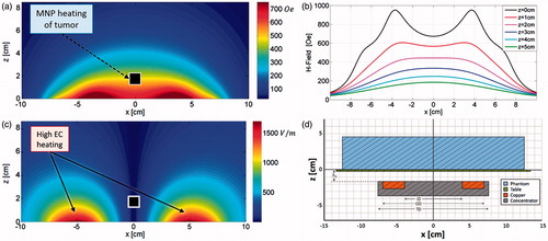
In this section we present techniques for mitigating eddy current heating which are particle agnostic and, when implemented well, do not affect MNP heating. These methods seek to take advantage of the inherent differences between the electric and magnetic field distributions in the near-field region of an AMF induction coil. shows the simulated magnetic field data (H-field) for a single-turn coil, inner diameter (ID) 8 cm, outer diameter (OD) 14 cm, with a magnetic core and a fixed amplitude alternating primary current. The coil is located in the xy plane at z = −1.55 cm (). Note the features of the field shape along the x-axis at various heights, which correspond to tissue depths (). The H-field map can be classified into three distinct regions. For z < ∼2 cm the H-field is highest near the coil conductor. At z ≈ 2 cm, the field strength is nearly constant within an ∼8 cm diameter circular area in the xy-plane. At z > ∼2 cm the field strength exhibits a single peak along the centre axis of the coil (i.e. where x = y = 0). Now compare these features to the electric field map (E-field) in . Generally the E-field can be characterised by one feature, strength decreases with distance from the conductor, with zero field along the centre axis. The importance of this comparison lies in the fact that magnetic nanoparticle heating depends on H-field strength, whereas eddy current induction depends upon E-field strength. Note that the following theoretical discussion pertains to an idealised thin loop system whose field distribution varies only slightly from that of the experimental system described in the methods section below; therefore, for the sake of brevity, only the field distributions for the experimental system are shown in .
Figure 1. Modelled magnetic (a) and electric (b) field distributions of the single-turn coil with a magnetic core located in the x-y plane at z = −1.55cm. (c) Magnetic field strength along x, at y = 0, for various z values. The transition between bimodal and unimodal behaviour occurs at z ≈ 2. (d) Cross-sectional diagram of the experimental setup at y = 0 (i.e. vertically bisecting the phantom), drawn to scale and further described in the methods section.
Tissue displacement
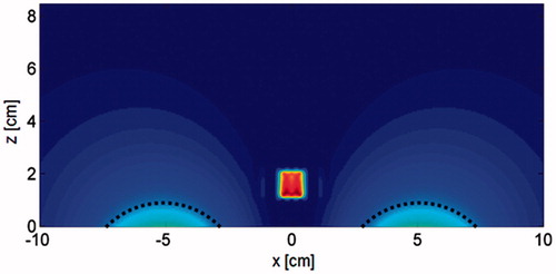
When a conductive object is placed over the coil an eddy current is induced which equals the product of the E-field in the object and its conductivity. Since electric field from a current source is inversely proportional to the distance from the source, we can reduce the maximum induced eddy current in the conductive target by displacing parts of the conducting volume away from regions of high electric field near the source. For a large rigid conductive body, this EC SAR reduction approach cannot be exploited. However, many tumour-bearing tissues are somewhat pliable and/or compressible, an exemplary case being breast tissue. By physically pushing the normal breast tissue away from the regions of highest E-field (indicated by the dashed lines in ) using a non-conductive spacer apparatus, the volume of space capable of producing the greatest eddy currents no longer contributes to the total current induced in the tissue. We have termed this method of eddy current heating mitigation the tissue displacement technique.
Figure 2. Modelled cross-sectional SAR distribution (xz-plane at y = 0) for a 0.6 S/m phantom with 1-cm3 uniformly distributed MNP inclusion. Regions of high EC SAR to be blocked by a tissue displacer are marked with dashed lines.
For idealised tissue where this perturbation would result in no translation of the tumour in z there is a clear benefit. In the case of tissue with realistic mechanical properties the tumour will move into a region of lower H-field, resulting in lower MNP SAR. If the MNP SAR were to decrease more than the maximum EC SAR the technique would be invalid. To address this concern, assume two extreme cases of a conducting half-space embedded with an MNP inclusion to simulate a tumour. First, a best-case scenario where the tumour does not shift in z, and second, a worst-case scenario where the tissue is completely rigid, resulting in a tumour shift in z equal to the tissue displacer height. Assume an optimal spacer shape on which E is equal on the entire surface, and that SARMNP varies linearly with H. If the primary coil current is increased to compensate for any decrease in H experienced by the tumour, the reduction in maximum SAREC can be calculated as:
(1)
Where z0 is the height of the treatment table (i.e. the initial position of the phantom), z1 is the maximum height of the spacer, z2 is the initial height of the tumour, z3 is the final height of the tumour.
In the best case scenario, z2 = z3, reducing EquationEquation 1(1) to:
(2)
Alternatively, when the coil current is increased such that max SAREC is equal in the control and displaced cases, the MNPSAR increases by:
(3)
For a conducting half-space z > 0, with a 7-cm thin loop coil at z = −1.55 cm, using a displacer with a maximum height of 2 cm, and an initial tumour depth of 2 cm, the reduction in maximum SAREC is 71% in the best case scenario, and 37% in the worst case scenario (EquationEquations 1(1) and Equation2
(2) ). Alternatively, SARMNP can be increased by 85% in the best case scenario, and 26% in the worst case scenario, when SAREC is kept constant between cases (EquationEquation 3
(3) ).
Motion
The second proposed method of eddy current heating mitigation is based on the lateral distribution of the magnetic field. This method is also a form of tissue displacement, but in contrast to the displacement method the total energy absorbed by the normal tissue is not reduced. Instead, the heat deposition per unit volume is spread out to a greater volume of tissue, thus decreasing the maximum energy absorption at any one point. This can be achieved in one of two ways; either the patient can be moved about with respect to the field, or the field can be moved about with respect to the patient. In practice, patient comfort and clinician ease of use will determine which method will be implemented. To illustrate the applicability of this technique, let us consider the case where the coil is moving slowly beneath a fixed treatment surface in a circular path with a radius of several centimetres. As the coil moves beneath the patient, the region of tissue exposed to the highest E-field is shifted gradually. As a result, in this case of constant relative motion, instead of the eddy currents following the same path for what might be a 1-h long treatment session (building up heat in the same regions throughout the therapy), the current is forced into different regions thereby resulting in distributed heating. We have termed this method of eddy current mitigation the ‘motion technique’.
The tumour depth and motion path radius both have an effect on the ratio of MNP SAR in the tumour to maximum EC SAR. Any decrease in H experience by the tumour due to the lateral shift away from the maximum will reduce MNP SAR. To address this concern, consider the simplified case of a homogeneous conducting half-space embedded with an MNP inclusion to simulate a tumour and assume SARMNP varies linearly with H. When the primary coil current is increased to compensate for any decrease in H experienced by the tumour, the reduction in maximum SAREC can be calculated as:
(4)
where max_s determines the spatial maximum within the conducting half-space, Ec is the electric field experienced by the conducting half-space in the static control case, and Em is the electric field experienced by the conducting half-space while the coil is in motion at position i, where the coil is moved to N positions throughout the total exposure time T, occupying each position for a period ti. The ratio of EC SARs is scaled by a factor C, which is determined as
(5)
where H is the rotationally symmetric magnetic field in cylindrical coordinates, rm is the radius of the motion path, and z0 is the height of the tumour.
In this scenario there is no effect on the secondary E-field due to discontinuities in electrical conductivity. Note that for a sufficiently small value of σ , as is the case with human tissue conductivities (generally σ < 1 S/m), the total electric field within the conducting half-space is not significantly perturbed. For a conducting half-space which exists for z ≥ 0, with the transmitting coil lying parallel to the boundary at z = −1.55 cm (within the non-conducting half-space), a simulated tumour depth, z0 = 1 cm (bimodal H-field zone), using a motion path radius, rm = 4.0 cm, the reduction in max SAREC is 44.8%. If instead z0 = 2 cm (transitional H-field zone), and rm = 3.8 cm, the reduction in maximum SAREC is 35.5%. When z0 = 3 cm (unimodal H-field zone) and rm = 3.8 cm the reduction in max SAREC is 28.9%. Alternatively, if the primary coil current is instead increased such that max SAREC is equal in the control and motion cases (EquationEquation 3(3) ), the resulting increases in SARMNP for these three cases are 34.6%, 24.5%, and 18.6%, respectively. In all cases the control tumour position was chosen to maximise SARMNP at the specified tumour height. Note that the path radii have been chosen to maximize SARMNP/SAREC (to within 2 mm of the optimal radii), ignoring thermal effects which may affect path optimisation.
Methods
AMF system
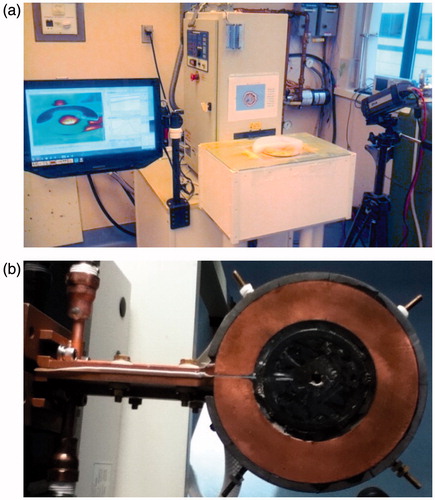
The AMF induction coil used in these experiments is a single-turn surface coil with a magnetic core (Fluxtrol, Auburn Hills, MI, USA). It is powered by a 25 kW generator (Radyne, Milwaukee, WI), which drives 135–400 kHz AC current through the coil, thus generating a 135–400 kHz AMF [Citation56]. The frequency used in the following experiments was 162 kHz. The coil () consists of a single turn of rectangular copper tubing with ID 8 cm, OD 14 cm, H 1 cm, with a magnetic core (Fluxtrol 75) which surrounds three sides of the tubing resulting in a total diameter (TD) of 15.2 cm (). The upper surface of the copper tubing faces the target tissue and is flush with the face of the magnetic material. A treatment table with airflow between the coil and table ensures the phantom or tissue is electrically and thermally isolated from the coil. The coordinate system has been chosen such that the table surface exists in the xy plane at z = 0, with the origin located along the centreline of the coil (). The distance between the coil surface and the table surface, h0, is 1.55 cm. Surface temperature distributions are measured using a thermal camera (Model SC325, FLIR Systems, Wilsonville, OR).
Figure 3. (a) AMF system with a phantom experiment in progress. The generator, treatment table, thermal camera, and thermal camera software interface are shown. (b) The induction coil is obscured from view in (a) by the treatment table.
Computational methods
The computational results presented in this paper were generated using a custom electromagnetics model, which implements the method of auxiliary sources (MAS), coupled with the Pennes bioheat equation.
MAS is a robust and accurate numerical technique for evaluating electromagnetic wave propagation and scattering problems [Citation61,Citation62]. In this method boundaries between materials of differing electrical parameters are defined and discretised into pairs of points along a surface. Each pair consist of an inner and outer point, which define fictitious surfaces both inside and outside of the true surface, and are designated as a dipole source with unknown magnitude and direction. These are the auxiliary sources, and they are evaluated directly using the boundary equations for the tangential components of the electric and magnetic fields. The result is a linear system of equations.
After the magnitudes of the auxiliary sources are determined, the fields in each region are evaluated as a sum of fields from the auxiliary sources of the fictitious surfaces [Citation63]. The accuracy of the MAS method was studied for the single-turn surface coil in [Citation56]. The coil was modelled using the manufacturer’s schematics and magnetic core material properties (Fluxtrol), and has been shown to be in good agreement with measured data [Citation56]. Once the electric field was computed, the SAR (W/kg) due to eddy currents was simply calculated as,
(6)
where σ is the electrical conductivity (S/m), J is the current density (A/m2), and ρ is the density of tissue (kg/m3). For the case of a non-uniform E-field, and an axially oriented non-permeable cylindrical target
(7)
where f is the frequency of the field (Hz), μ0 is the permeability of free space [Citation64]. Furthermore, in the case a constant H-field [Citation25,Citation64]
(8)
However, even for an idealised solenoid, there is a non-zero axial E-field due to the angle of the turns relative to z, and significant coupling between turns; thus, one must use the general case (EquationEquation 6(6) ) to describe real world systems. Additionally, the SAR due to MNP is estimated by using the computed magnetic fields and MNP distributions. The total SAR is calculated as
(9)
where SARMNP is determined using the MNP heating model discussed in Shubitidze et al. [Citation35] and Stigliano et al. [Citation65]. Finally, the total SAR distribution and thermal boundary conditions are fed into the Pennes bioheat equation [Citation66,Citation67] which is solved using a standard finite difference time domain method [Citation68–70].
In the computational studies cylindrical phantoms (D = 25.0 cm, H = 4.5 cm) were modelled with electrical conductivity 0.6 S/m, thermal conductivity 0.58 W/[m·°C], specific heat 4182 J/[kg·°C] density 998 kg/m3, and exposed to the simulated AMF of a single-turn coil. This simplified geometry was chosen to minimise confounding factors affecting eddy current heating such as inhomogeneities and boundary effects in a system that could be accurately recreated experimentally. The electrical conductivity was set to the value of human muscle which fell at the high end of values reported at 100 kHz [Citation71]. Final thermal distributions were determined using boundary conditions simulating natural convection (heat transfer coefficient, hT = 10 W/[m2·°C]) at all surfaces except the bottom surface, for which an insulating boundary condition was implemented (hT = 0).
Displacement-specific computational methods
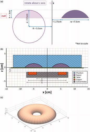
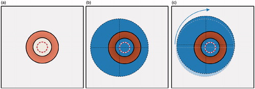
A simulated phantom was modelled with an embedded torus section (ID = 3.5 cm, OD = 18.5 cm, H = 2.0 cm) electrical insulator (), to model the effect of displacing tissue away from the highest electric field region. A second simulation of an identical phantom with no insulating displacer was modelled for comparison.
Figure 4. (a) A 2D cross-sectional diagram showing the geometry and relevant dimensions of the displacer. (b) 3D model of toroid section-shaped tissue displacer. (c) Cross-sectional diagram of the experimental set-up at y = 0 (drawn to scale).
Motion-specific computational methods
The simulated phantom was initially positioned 2.5 cm off centre from the coil. It was translated at 30-s intervals to one of 12 different positions, with a total exposure time of 30 min. Each position was radially 2.5 cm distant from the centreline of the coil with a 30° angle between them (). Note that due to the asymmetry of the modelled system at a single position, the magnetic core of the coil was not modelled (air core). Due to the rotational symmetry inherent to the motion, the remaining 11 SAR distributions can be inferred from the first by simply rotating the resulting SAR distribution in the xy-plane, about the centre of the phantom, in increments of 30° ().
Figure 5. Top-down diagram of phantom positions during ECM-motion technique, note the phantom is positioned above the coil. (a) Coil position (copper coloured ring) shown with 12 positions for placement of the centre of the phantom. (b) Phantom (blue, dashed outline) in position 1, and (c) in position 2. Note that the phantom is simply translated to the next position and undergoes no rotation.
Experimental methods
For experimental verification of the computational results, cylindrical phantoms (D = 25.0 cm, H = 4.5 cm) were constructed using 20 g agarose, 2.6 g NaCl, and 2 L deionised water. All phantoms were created with the highest reported values for electrical conductivity of human muscle (0.6Ω−1·m−1 at 100 kHz) [Citation71]. The temperature distribution of the surface of the phantoms was measured using a thermal camera. Each phantom was exposed to AMF at 16.25 kW nominal generator power setting for 30 min. The phantoms were cut immediately after heating and half of the phantom was flipped up onto the other half to expose the cut faces to the thermal camera, resulting in a mirror image with a horizontal axis of symmetry.
Displacement-specific experimental methods
A laminated wooden spacer was fabricated to the specifications shown in . Due to the phantom material’s lack of compressibility and elasticity, the wooden spacer was embedded in the phantom to mimic the displacement of compressible tissue (). The resulting phantom retained the diameter and volume of the control (non-displaced) phantom; however, the height increased slightly.
Motion-specific experimental methods
The control phantom was positioned centrally on the table over the induction coil on a plastic sheet of transparency paper <0.2 mm thickness to facilitate moving the phantom without compromising it mechanically. The motion phantom was initially placed 2.5 cm off centre from the coil. It was then moved at 30-s intervals during AMF exposure, by sliding (translating) the phantom along the table to one of 12 different positions, each position was radially 2.5 cm distant from the centreline of the coil with a 30° angle between them.
Tissue displacement results
Computational study
The resulting SAR distributions are shown in and . Note that at the base of the phantom (z = 0), the total SAR in the plane is strongly reduced due to the presence of the displacer. At z > 2 cm the SAR distributions are identical, with and without the spacer, because current distribution is unaffected in this region. In this simulation, total power absorption in the phantom is decreased by 55%.
Figure 6. Modelled cross-sectional SAR distributions of control and displaced phantoms at z = 0, 2, and 4 cm (i.e. the base of the phantom, the height of the displacer, and 2 cm above the displacer).
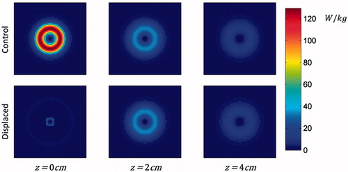
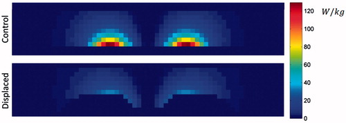
Figure 7. SAR distribution for control and displaced phantoms. Cross-sections shown at y = 0 cm.
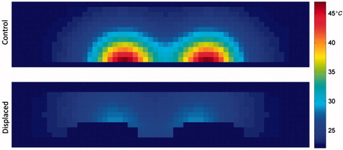
Including the effects of thermal diffusion throughout the phantom and heat transfer with the environment results in a 74% decreased maximum temperature change in the displaced phantom as compared to the non-displaced control ( and ). The plane in which the maximum temperature point exists (control, z = 0; displaced, z = 2 cm) exhibits lower temperatures throughout the 30-min exposure (). From the cross-sectional view in it can be seen that the spacer has greatly reduced the temperature of the material closest to the coil, and that the shape has not been optimised to reduce the maximum temperature point while displacing the least possible volume of tissue.
Figure 8. Resulting temperature distribution at various time points for the control phantom at z = 0 cm, and the displaced phantom at z = 2 cm. The cross-sections shown each contain the maximum temperature.
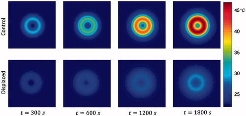
Figure 9. Resulting temperature distribution at t = 1800 s, y = 0 cm, for the control and displaced phantoms.
Following the analysis for an initial tumour depth of 2 cm above, the reduction in maximum SAREC is 76% in the best case scenario, and 23% in the worst case scenario (EquationEquations 1(1) and Equation2
(2) ). Alternatively, SARMNP can be increased by 104% in the best case scenario, and 14% in the worst case scenario, when SAREC is kept constant between cases (EquationEquation 3
(3) ).
Experimental study
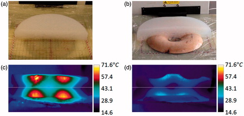
The phantoms each began at 23°C. The control phantom reached a maximum cross-sectional temperature of 71°C at 100 s post-exposure (t = 1900 s), the displaced phantom reached 34°C (). This represents a 77% reduction in maximum temperature change.
Figure 10. Position of bottom half of control phantom (a) and displaced phantom (b) after sectioning. Resulting cross-sectional temperature distributions at t = 1900 s for control (c) and displaced phantoms (d).
Field–tissue motion results
Computational study
The resulting SAR distribution for the phantom shifted to x = −2.5 cm, y = 0 cm is shown in and . As compared to the control case (i.e. phantom centred over coil), placing the phantom in the offset position causes not only a shift in the SAR distribution relative to the phantom, but also an asymmetry in the SAR distribution within the phantom, which is weighted toward the origin (i.e. coil center). Note also that at a single offset position asymmetries are experienced not only laterally (), but also vertically (), due to the discontinuity at the boundary. As a consequence of this effect, in the case of realistic (non-homogeneous) tissue, deeper regions may experience greater EC heating due to the effect of electrical discontinuities, especially at air − tissue interfaces (discussed further in the results section).
Figure 11. Diagram of phantom in (a) control position, i.e. centred over coil, (b) resulting SAR distribution of phantom in control position at z = 0 cm, (c) diagram of phantom in position 1 (x = −2.5 cm, y = 0 cm), (d) resulting SAR distribution of phantom at position 1, (cross-section shown at z = 0 cm).
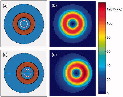
Figure 12. SAR distribution of the centred control phantom, and of the motion phantom at position 1. Cross sections shown at y = 0 cm.
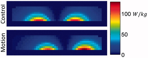
If the phantom were left in a single offset position throughout the entirety of the 30-min exposure the maximum temperature achieved would increase; however, by moving the phantom between the 12 offset positions the region of phantom which experiences the highest SAR at any one position is only heated at the maximum rate for 1/12 of the time. With the effects of thermal diffusion throughout the phantom, and heat transfer with the environment, the result is a broader temperature distribution ( and ). In this simulation, the difference in total power absorption between the control and motion phantom is minimal (<4% decrease) and the maximum SAR at a single offset position is actually 13% higher; however, the time-averaged SAR distribution shows a 28% decrease in maximum SAR. This resulted in a 19% decreased maximum temperature change in the motion phantom as compared to the static control.
Figure 13. Resulting temperature distribution at the base of the phantom (z = 0 cm), for various time points, with the phantom in the control position (centred) throughout the exposure, and having moved between the 12 offset positions at 30-s intervals throughout the exposure.
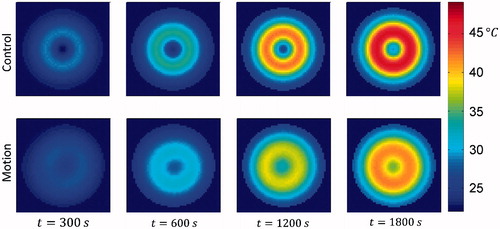
Figure 14. Resulting temperature distribution at t = 1800 s, with the phantom in the control position throughout the exposure, and having moved between the 12 offset positions at 30-s intervals throughout the exposure. Cross-sections shown in the xz-plane at y = 0 cm, i.e. bisecting the phantoms.
Considering a tumour located at z = 1.7 cm, i.e. at the transition height between bimodal and unimodal behaviour of the H-field, the reduction in maximum SAREC is 28% (EquationEquations 4(4) and Equation5
(5) ). At this height there is no change in SARMNP between the control and motion cases since the tumour experiences the same magnetic field strength in the control and the offset position. If the primary coil current is instead increased to keep max SAREC equal between the control and displaced cases, the resulting increase in SARMNP is 18% (EquationEquation 3
(3) ).
Experimental study
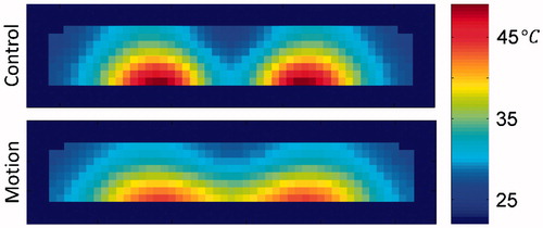
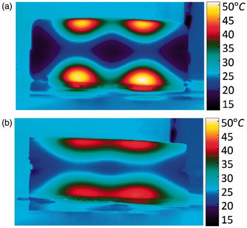
The control phantom began at 6°C and rose to a maximum cross-sectional temperature of 51°C at 90 s post-exposure (). The motion phantom began at 11°C and rose to a maximum cross-sectional temperature of 42°C (). This represents a 33% reduction in maximum temperature change.
Figure 15. Resulting cross-sectional temperature distributions at t = 1890 s (90 s post-exposure) for (a) control and (b) motion phantoms.
Discussion
Tissue displacement
In the tissue displacement study it was shown both computationally and experimentally that physically displacing the phantom away from the areas of high E-field decreased the maximum temperature induced by 74% and 77% respectively. As shown in EquationEquation 6(6) the current induced per unit volume is dictated by the electric field strength and the conductivity. Therefore, by essentially changing the conductivity in regions of space coinciding with high E-field from 0.6 S/m to 0 S/m, any current which would have been induced in this volume is no longer generated. This resulted in decreased total energy absorbed by the phantom and thus decreased maximum temperature.
Ultimately, the greatest limitation of this technique will likely be the anatomical position of the treatment site, such as tumours near tissue with low compressibility. Breast cancer tumours are likely to be the most favourable target since breast tissue is highly compressible. This technique will yield the best results when the clinically practical tissue displacement is greatest; however, any amount of displacement away from the regions of high E-field will yield a decrease in eddy current heating.
In this study the displacer used in the phantom experiment was not optimised to block the maximum E-field with the minimum tissue displacement necessary. Also, anatomical restrictions, the mechanical properties of the tissue affecting tumour displacement, and the coil design will dictate the shape of the optimal displacer on a case-by-case basis. Ultimately, these results warrant further study of displacer design and the efficacy of this technique when applied to specific disease sites with complex tissue geometry, as well as electrical, thermal and mechanical properties.
Field–tissue motion
In the motion study it was shown that relatively small movements of the phantom with respect to the coil can significantly reduce the maximum temperature induced. In the phantom this reduction in maximum temperature change was shown to be 19% computationally and 33% experimentally. The concept behind this effect is fundamentally different from the tissue displacement technique. Instead of relying primarily on decreasing the total energy absorbed by the tissue, this technique causes energy to be distributed more evenly throughout the tissue. In the control case the same region of tissue is exposed to the maximum current density throughout the entire AMF exposure. By moving the tissue within the field during the exposure, different volumes of tissue are exposed to the highest current density at different times, and the maximum temperature induced is determined by a combination of time-averaged current densities, electrical conductivity, and thermal diffusion.
It should be noted that, under certain circumstances this technique has the potential to cause greater eddy current heating in non-homogeneous tissue. This could happen due to inhomogeneities in electrical conductivity affecting the current distribution. At any instant in time there is a distinct current density distribution throughout the tissue. Consider the simplified case of inhomogeneous electrical properties and homogeneous thermal properties. In the static case the volume which develops the highest temperature will be that which has the highest net volumetric heat. It is theoretically possible that maximum volumetric current density can be increased from the homogeneous tissue case, due to low conductivity inclusions within the high E-field region, causing the current to divert its course to a smaller cross section of tissue. Considering this effect in the motion technique case, higher maximum current density could occur, compared to an optimal static position. This type of effect is observed in , where increased SAR occurs near the edge of the phantom; this is a result of the change in the current distribution caused by the material discontinuity at the edge and its position relative to the coil. With this potential drawback noted, it should be stated that the impact of these positions with higher local SAR is marginalised by the use of continual motion, ensuring no one position is held for an extended time, averaging the effect. In addition to the potential to decrease maximum temperature, this technique also has the advantage of minimising the patient-to-patient and treatment-to-treatment eddy current heating variability which is inherent in patients due to complex tissue.
Determining the optimal path radius in the case of a simplified homogeneous half-space such as that presented in the theory section above simply consists of determining the motion radius which results in maximum SARMNP/SAREC for the given field distribution, tumour depth, and MNPSAR dependence on H. However, for inhomogeneous tissue the optimal motion path will likely be more complex than a simple circular path and may not be limited to two-dimensional translation, depending on the specific treatment site in question. The optimal path will likely be patient/treatment-specific, and would be best implemented using a robust treatment planning model. For instance, in the case of breast cancer a treatment planning model would need to take into account tumour location, depth, and size, as well as the thermal and electrical properties of the tissue exposed to the field. It would also need to take into consideration the geometry of the surface of the patient’s body to determine feasible coil positions, then iterate through simulated motion paths to maximise the minimum thermal dose in the tumour while maintaining the maximum allowable thermal dose to normal tissue by modulating the coil current. Ideally the patient would be treated on a fixed surface with the field source mounted on an electromechanical mechanism similar to the gantry of a clinical linear accelerator (used in external beam radiation treatments). These results for homogeneous tissue warrant further study, including the development of the motion optimisation component, and evaluation in complex tissue.
Applicability to other coil types
Though a single-turn surface coil was chosen as the model system in this work, these methods can be generalised to both classes of MNP coils, namely surface coils and tissue-encompassing coils. The results presented apply directly to any coil used as a surface coil, including single-turn, pancake, solenoid, and by extension, to simultaneous application of multiple coils as is the case with a Helmholtz coil. What has not been directly shown is the application of these techniques to tissue-encompassing coils, i.e. when the treatment area is placed within the coil. Any of the aforementioned coil configurations, with the exception of a full-spiral pancake coil, can be used in this manner. Consider the case of a tissue-encompassing solenoid of finite length L and radius R, with z, as the axis of symmetry. In this case, for any z, the electric field is strongest at the conductor and falls off radially towards the centre. Additionally, the electric field is strongest at L/2 and falls off towards both ends of the coil. Thus, displacement of tissue away from the conductor is still beneficial when the tissue can be displaced throughout a significant length of the coil (i.e. the displaced tissue is pushed towards the ends of the coil bore). The motion technique also has potential with the solenoid case in which the electric field is spread throughout a larger volume of tissue by continuously moving the coil, either by translation along the axis of symmetry, by radial gyration, by precession, or some combination of these motions. The potential of EC heating mitigation techniques illustrated for the case of a single-turn surface coil warrant further study regarding various coil configurations and specific clinical applications.
Conclusions
UndesIHYTle eddy current heating presents a major challenge in MNP hyperthermia therapy. Existing works have focused on methods of increasing MNP heating in tumours without attempting to modify EC heating. In this paper two novel methods for decreasing the maximum temperature induced by eddy currents are presented. The motion technique involved moving the tissue relative to the coil during the exposure. In phantom studies this resulted in a decrease in the maximum temperature change in normal tissue of 19% in simulation and 33% experimentally. The displacement technique involved selectively shifting normal tissue away from regions of high E-field. In phantom studies this resulted in simulated and experimental reductions of 74% and 77%, respectively. These results suggest that larger volumes of tissue with deeper tumours could be treated, and that higher field strengths and frequencies could be used for MNP hyperthermia, thereby attaining improved treatment efficacy. Further study is required to optimise these methods.
Disclosure statement
The authors alone are responsible for the content and writing of the paper.
Funding
This work was supported by the Dartmouth Cancer Center of Nanotechnology Excellence via funding provided through the National Cancer Institute of the National Institutes of Health under Award Number 1U54CA151662-05. L.S. acknowledges financial support from the Georgian National Science Foundation under grant D13/21. This work expresses the opinions of the authors only and not necessarily the views of the funding agencies.
References
- Giustini AJ. Magnetic nanoparticle hyperthermia in cancer treatment. Nano Life 2010;1:17–32.
- Cassim SM, Giustini AJ, Petryk AA, Strawbridge RR, Hoopes PJ. Iron oxide nanoparticle hyperthermia and radiation cancer treatment. 2009;7181:71810O.
- Oleson JR, Calderwood SK, Coughlin CT, Dewhirst MW, Gerweck LE, Gibbs FA, et al. Biological and clinical aspects of hyperthermia in cancer therapy. Am J Clin Oncol 1988;11:368–80.
- Sekhar KR, Sonar V, Muthusamy V, Sasi S, Laszlo A, Sawani J, et al. Novel chemical enhancers of heat shock increase thermal radiosensitization through a mitotic catastrophe pathway. Cancer Res 2007;67:695–701.
- Kampinga HH, Dikomey E. Hyperthermic radiosensitization: mode of action and clinical relevance. Int J Radiat Biol 2001;77:399–408.
- Vernon CC, Hand JW, Field SB, Machin D, Whaley JB. Radiotherapy with or without hyperthermia in the treatment of superficial localized breast cancer: results from five randomized controlled trials. Int J Radiat Oncol Biol Phys 1996;35:731–44.
- Jones EL, Oleson JR, Prosnitz LR, Samulski TV, Vujaskovic Z, Yu D, et al. Randomized trial of hyperthermia and radiation for superficial tumors. J Clin Oncol 2005;23:3079–85.
- Overgaard J, Gonzalez Gonzalez D, Hulshof MC, Arcangeli G, Dahl O, Mella O, Bentzen SM. Randomised trial of hyperthermia as adjuvant to radiotherapy for recurrent or metastatic malignant melanoma. Lancet 1995;345(8949):540–3.
- Issels RD, Lindner LH, Verweij J, Wust P, Reichardt P, Schem BC, et al. Neo-adjuvant chemotherapy alone or with regional hyperthermia for localised high-risk soft-tissue sarcoma: a randomised phase 3 multicentre study. Lancet Oncol 2010;11:561–70.
- Valdagni R, Amichetti M, Pani G. Radical radiation alone versus radical radiation plus microwave hyperthermia for N3 (TNM-UICC) neck nodes: a prospective randomized clinical trial. Int J Radiat Oncol Biol Phys 1988;15:13–24.
- Horsman MR, Overgaard J. Hyperthermia: a potent enhancer of radiotherapy. Clin Oncol 2007;19:418–26.
- Petryk AA, Giustini AJ, Gottesman RE, Kaufman PA, Hoopes PJ. Magnetic nanoparticle hyperthermia enhancement of cisplatin chemotherapy cancer treatment. Int J Hyperthermia 2013;29:845–51.
- Pankhurst QA, Connolly J, Jones SK, Dobson J. Applications of magnetic nanoparticles in biomedicine. J Phys D Appl Phys 2003;36:13.
- Ito A, Shinkai M, Honda H, Kobayashi T. Medical application of functionalized magnetic nanoparticles. J Biosci Bioeng 2005;100:1–11.
- McCarthy JR, Weissleder R. Multifunctional magnetic nanoparticles for targeted imaging and therapy. Adv Drug Del Rev 2008;60:1241–51.
- Grüttner C, Müller K, Teller J, Westphal F, Foreman A, Ivkov R. Synthesis and antibody conjugation of magnetic nanoparticles with improved specific power absorption rates for alternating magnetic field cancer therapy. J Magn Magn Mater 2007;311:181–6.
- Goya GF, Asín L, Ibarra MR. Cell death induced by AC magnetic fields and magnetic nanoparticles: current state and perspectives. Int J Hyperthermia 2013;29:810–18.
- Petryk AA, Giustini AJ, Gottesman RE, Trembly SB, Hoopes PJ. Comparison of magnetic nanoparticle and microwave hyperthermia cancer treatment methodology and treatment effect in a rodent breast cancer model. Int J Hyperthermia 2013;29:819–27.
- Magforce AG. Overview. Available from http://www.magforce.de/en/studien.html (accessed September 2014).
- Maier-Hauff K, Rothe R, Scholz R, Gneveckow U, Wust P, Thiesen B, et al. Intracranial thermotherapy using magnetic nanoparticles combined with external beam radiotherapy: results of a feasibility study on patients with glioblastoma multiforme. J Neurooncol 2007;81:53–60.
- Johannsen M, Thiesen B, Wust P, Jordan A. Magnetic nanoparticle hyperthermia for prostate cancer. Int J Hyperthermia 2010;26:790–5.
- Wust P, Gneveckow U, Johannsen M, Bohmer D, Henkel T, Kahmann F, et al. Magnetic nanoparticles for interstitial thermotherapy – feasibility, tolerance and achieved temperatures. Int J Hyperthermia 2006;22:673–85.
- Johannsen M, Gneveckow U, Taymoorian K, Thiesen B, Waldofner N, Scholz R, et al. Morbidity and quality of life during thermotherapy using magnetic nanoparticles in locally recurrent prostate cancer: results of a prospective phase I trial. Int J Hyperthermia 2007;23:315–23.
- Maier-Hauff K, Ulrich F, Nestler D, Niehoff H, Wust P, Thiesen B, et al. Efficacy and safety of intratumoral thermotherapy using magnetic iron-oxide nanoparticles combined with external beam radiotherapy on patients with recurrent glioblastoma multiforme. J Neurooncol 2011;103:317–24.
- Atkinson WJ, Brezovich IA, Chakraborty DP. Useable frequencies in hyperthermia with thermal seeds. IEEE Trans Biomed Eng 1984;31:70–75.
- Tegopoulos JA, Kriezis EE. Eddy current distribution in plates. Oxford: Elsevier Science, 1985, pp. 60–70.
- Nieskoski MD, Trembly BS. Comparison of a single optimized coil and a Helmholtz pair for magnetic nanoparticle hyperthermia. IEEE TransBiomed Eng 2014;61:1642–50.
- Wabler M, Zhu W, Hedayati M, Attaluri A, Zhou H, Mihalic J, et al. Magnetic resonance imaging contrast of iron oxide nanoparticles developed for hyperthermia is dominated by iron content. Int J Hyperthermia 2014;30:192–200.
- Hedayati M, Attaluri A, Bordelon D, Goh R, Armour M, Zhou H, et al. New iron-oxide particles for magnetic nanoparticle hyperthermia: an in-vitro and in-vivo pilot study. Proc SPIE 2013;8584:858404.
- Rosensweig RE. Heating magnetic fluid with alternating magnetic field. J Magn Magn Mater 2002;252:370–4.
- Hergt R, Dutz S, Roder M. Effects of size distribution on hysteresis losses of magnetic nanoparticles for hyperthermia. J Phys Condens Matter 2008;20:1–12.
- Alphandery E, Faure S, Seksek O, Guyot F, Chebbi I. Chains of magnetosomes extracted from AMB-1 magnetotactic bacteria for application in alternative magnetic field cancer therapy. ACS Nano 2011;5:6279–96.
- Kekalo K, Koo K, Zeitchick E, Baker I. Microemulsion synthesis of iron core/iron oxide shell magnetic nanoparticles and their physicochemical properties. Mater Res Soc Symp Proc 2012;1416:PMC4633094.
- Zhang G, Liao Y, Baker I. Surface engineering of core/shell iron/iron oxide nanoparticles from microemulsions for hyperthermia. Mater Sci Eng C 2010;30:92–7.
- Shubitidze F, Kekalo K, Stigliano R, Baker I. Magnetic nanoparticles with high specific absorption rate of electromagnetic energy at low field strength for hyperthermia therapy. J Appl Phys 2015;117:094302.
- Storm G, Belliot S, Daemen T, Lasic D. Surface modification of nanoparticles to oppose uptake by the mononuclear phagocyte system. Adv Drug Del Rev 1995;17:31–48.
- Giustini A, Petryk A, Hoopes P. Ionizing radiation increases systemic nanoparticle tumor accumulation. Nanomed Nanotech Biol Med 2012;8:818–21.
- Petryk AA, Giustini AJ, Gottesman RE, Hoopes PJ. Improved delivery of magnetic nanoparticles with chemotherapy cancer treatment. Proc SPIE Int Soc Opt Eng 2013;8584:85840H.
- Chauhan V, Stylianopoulos T, Martin J, Popović Z, Chen O, Kamoun W, et al. Normalization of tumour blood vessels improves the delivery of nanomedicines in a size-dependent manner. Nat Nanotech 2012;7:383–8.
- Jain R, Stylianopoulos T. Delivering nanomedicine to solid tumors. Nat Rev Clin Oncol 2010;7:653–64.
- Tate J, Kett W, Dong CN, Griswold K, Hoopes P. Biodistribution of antibody-targeted and non-targeted iron oxide nanoparticles in a breast cancer mouse model. Proc SPIE 2013;8584:85840G.
- Jordan A, Scholza R, Maier-Hauffb K, Johannsenc M, Wusta P, Nadobnya J, et al. Presentation of a new magnetic field therapy system for the treatment of human solid tumors with magnetic fluid hyperthermia. J Magn Magn Mater 2001;225:118–26.
- Gneveckow U, Jordan A, Scholz R, Brüss V, Waldöfner N, Ricke J, et al. Description and characterization of the novel hyperthermia- and thermoablation- system MFH® 300F for clinical magnetic fluid hyperthermia. Med Phys 2004;31:1444–51.
- Stauffer P, Cetas T, Jones R. Magnetic induction heating of ferromagnetic implants for inducing localized hyperthermia in deep-seated tumors. IEEE Trans Biomed Eng 1984;31:235–51.
- Stauffer P, Cetas T, Fletcher A, DeYoung D, Dewhirst M, Oleson J, et al. Observations on the use of ferromagnetic implants for inducting hyperthermia. IEEE Trans Biomed Eng 1984;31:76–90.
- Lerch A, Kohn S. Radiofrequency hyperthermia: the design of the coil transducers for local heating. Int J Radiat Oncol Biol Phys 1983;9:939–48.
- Kumar A, Attaluri A, Mallipudi R, Cornejo C, Bordelon D, Armour M, et al. Method to reduce non-specific tissue heating of small animals in solenoid coils. Int J Hyperthermia 2013;29:106–20.
- Brezovich I, Young J, Wang M. Temperature distributions in hyperthermia by electromagnetic induction: a theoretical model for the thorax. Med Phys 1983;10:57–65.
- Oh S, Ryu Y, Carluccio G, Sica C, Collins C. Measurement of SAR-induced temperature increase in a phantom and in vivo with comparison to numerical simulation. Magn Reson Med 2014;71:1923–31.
- Zhao H, Crozier S, Feng L. Finite difference time domain (FDTD) method for modeling the effect of switched gradients on the human body in MRI. Magn Reson Med 2002;48:1037–42.
- Crozier S, Wang H, Trakic A, Feng L. Exposure of workers to pulsed gradients in MRI. J Magn Reson Imaging 2007;26:1236–54.
- Crozier S, Trakic WH, Feng L. Numerical study of currents in workers induced by body-motion around high-ultrahigh field MRI magnets. J Magn Reson Imaging 2007;26:1261–77.
- Feng L, Crozier S. A distributed equivalent magnetic current based FDTD method for the calculation of E-fields induced by gradient coils. J Magn Reson 2004;169:323–27.
- Lopez H, Poole M, Crozier S. Eddy current simulation in thick cylinders of finite length induced by coils of arbitrary geometry. J Magn Reson 2010;207:251–61.
- Bohnert J, Dossel O. Effects of time varying currents and magnetic fields in the frequency range of 1 kHz to 1 MHz to the human body – a simulation study. Conf Proc IEEE Eng Med Biol Soc 2010;2010:6805–8.
- Stigliano RV, Shubitidze F, Petryk AA, Tate JA, Hoopes PJ. Magnetic nanoparticle hyperthermia: predictive model for temperature distribution. Proc SPIE Int Opt Soc Eng 2013;8584:858410.
- Barba PD, Dughiero F, Sieni E, Candeo A. Coupled field synthesis in magnetic fluid hyperthermia. IEEE Trans Magn 2010;47:914–17.
- Candeo A, Dughiero F. Numerical FEM models for the planning of magnetic induction hyperthermia treatments with nanoparticles. IEEE Trans Magn 2009;45:1658–61.
- Barnes GT. Mammography equipment: compression, scatter control and automatic exposure control. In: Haus AG, Yaffe MJ, eds. Syllabus: A categorical course in physics – Technical aspects of breast imaging. Oak Brook, Illinois: Radiological Society of North America, 1992, pp. 59–68.
- Poulos A, McLean D. The application of breast compression in mammography: a new perspective. Radiography 2004;10:131–7.
- Bijamov A, Shubitidze F, Oliver P, Vezenov D. Optical response of magnetic fluorescent microspheres used for force spectroscopy in the evanescent field. Langmuir 2010;26:12003–11.
- Bijamov A, Shubitidze F, Oliver P, Vezenov D. Quantitative modeling of forces in electromagnetic tweezers. J Appl Phys 2010;108:104701.
- Shubitidze F, O'Neill K, Haider SA, Sun K, Paulsen KD. Application of the method of auxiliary sources to the wide-band electromagnetic induction problem. IEEE Trans Geosci Remote Sens 2002;40:928–42.
- Oleson JR. Hyperthermia by magnetic induction: I. Physical characteristics of the technique. Int J Radiat Oncol Biol Phys 1982;8:1747–56.
- Stigliano RV, Shubitidze F, Kekalo K, Baker I, Giustini AJ, Hoopes PJ. Understanding mNP hyperthermia for cancer treatment at the cellular scale. Proc SPIE 2013;8584:85840E.
- Pennes HH. Analysis of tissue and arterial blood temperatures in the resting human forearm. 1948;1:93–122.
- Kuznetsov AV. Optimization problems for bioheat equation. Int Commun Heat Mass Transf 2006;33:537–43.
- Bijamov A, Razmadze A, Shoshiashvili L, Tavzarashvili K, Zaridze R, Bit-Babik G, Faraone A. Advanced electro-thermal analysis for the assessment of human exposure in the near-field of EM sources. Proc Int Conf Electromagn Adv Appl 2003;3:8–12.
- Razmadze A, Shoshiashvili L, Kakulia D, Zaridze R, Bit-Babik G, Faraone A. Influence of specific absorption rate averaging schemes on correlation between mass-averaged specific absorption rate and temperature rise. Electromagnetics 2009;29:77–90.
- Shoshiashvili L, Razmadze A, Jejelava N, Zaridze R, Bit-Babik G, Faraone A. Validation of numerical bioheat FDTD model. In IEEE Proceedings of XI-11th International Workshop on Direct and Inverse Problems of Electromagnetic and Acoustic Wave Theory 2006, pp. 201–4.
- Solazzo SA, Liu Z, Lobo SM, Ahmed M, Hines-Peralta A, Lenkinski RE, Goldberg SN. Radiofrequency ablation: importance of background tissue electrical conductivity – an agar phantom and computer modeling study. Radiology 2005;236:495–502.