
 ?Mathematical formulae have been encoded as MathML and are displayed in this HTML version using MathJax in order to improve their display. Uncheck the box to turn MathJax off. This feature requires Javascript. Click on a formula to zoom.
Abstract
Background
Chronic back pain due to facet related degenerative changes affects 4-6 million patients a year in the United States. Patients refractory to conservative therapy may warrant targeted injections of steroids into the joint or percutaneous medial branch nerve denervation with radiofrequency ablation. We numerically tested a novel noninvasive high intensity focused ultrasound transducer to optimize nerve ablation near a bone-soft tissue interface.
Methods
A transducer with 4 elements operating in an incoherent mode was modeled numerically and tested pre-clinically under fluoroscopic guidance. After 6 lumbar medial branch nerve ablations were performed in 2 pigs, they were followed clinically for 1 week and then sacrificed for pathological evaluation.
Results
Simulations show that the acoustic spot size in water at 6 dB was 14mm axial x 1.6mm lateral and 52mm axial x 1.6mm lateral for coherent and incoherent modes, respectively. We measured the size of N = 6 lesions induced in vivo in a pig model and compared them to the size of the simulated thermal dose. The best match between the simulated and measured lesion size was found with a maximum absorption coefficient in the cortical bone adjusted to 30 dB/cm/MHz. This absorption was used to simulate clinical scenarios in humans to generate lesions with no potential side effects at 1000 and 1500 J.
Conclusion
The elongated spot obtained with the incoherent mode facilitates the targeting during fluoroscopic-guided medial branch nerve ablation.
Introduction
Chronic back pain is a common condition with more than 27 million Americans affected each year [Citation1]. Chronic back pain is one of the major factors contributing to lost workdays and has forced approximately 19% of people suffering from this condition to quit their jobs [Citation2]. 15–25% of these patients, or about 4–6 million patients a year in the USA have chronic zygapophyseal joint back pain caused by chronic inflammation and degeneration of the lumbar facet joints [Citation3–8].
The first line treatment of chronic low back pain includes oral non-opioid medication, physiotherapy and lifestyle changes. If these fail, targeted injections of steroids into the joint and sensory nerve ablations are therapeutic alternatives [Citation3–8]. Zygapophyseal joint denervation is achieved by ablation of the medial branch nerves (MBN) supplying the joint. The MBN can be targeted and treated in a controlled manner with various methods. The most common procedure is thermal radiofrequency ablation (RFA), where an operator uses X-ray fluoroscopy to correctly position a cannula where the lumbar medial branch of the targeted vertebra is located [Citation3–8]. The cannula causes the tissue temperature near the tip to increase and cause an oval-shaped tissue coagulation at the target site. Despite its effectiveness, this procedure has side effects and complications. The most common side effects are pain and discomfort associated with percutaneous insertion of the radiofrequency cannula [Citation3–8]. More serious complications include bleeding and infections. Thus, a noninvasive alternative with the same efficacy is desirable.
High intensity focused ultrasound (HIFU) is a novel technology enabling image guided noninvasive thermal ablation [Citation9,Citation10]. This technology has been gaining significant popularity and acceptance in recent years [Citation11–13]. In the field of musculoskeletal applications, FUS has been found to be clinically effective for multiple palliative treatments [Citation14] including lumbar zygaphophyseal joint pain [Citation15,Citation16], bone metastasis [Citation17–19], osteoarthritis [Citation20] and osteoid osteoma [Citation21].
The goal of using HIFU is to deliver energy into the patient’s body by focusing an ultrasonic beam. The energy is focused geometrically or electronically on a targeted region to cause bio-effects, hopefully leading to a therapeutic effect. HIFU and high intensity therapeutic ultrasound (HITU) refer to focused ultrasound that is being transmitted at a high acoustic intensity, on the order of 102–103 W/cm2. The goal is to control ablation in a localized region and avoid damage to neighboring tissue. The bio-effects at the focal point can be mechanical, thermal or a combination of the two and must be considered when using HIFU treatments near sensitive anatomy [Citation22]. The mechanical effects range from an increase membrane permeability to tissue emulsification (i.e. histotripsy) [Citation23]. The thermal effects range from mild hyperthermia to thermal coagulation. Although all these effects have been investigated intensively, the thermal effects are more predictable and controllable and are already exploited in clinical practice following regulatory approval in many countries [Citation9,Citation11].
In Europe and Asia, HIFU is approved for the treatment of liver [Citation24], pancreatic [Citation25,Citation26], breast [Citation27] and prostate cancer [Citation28,Citation29], brain thalamotomy [Citation30,Citation31] and painful bone metastasis [Citation18,Citation19]. In the US, HIFU is approved for the treatment of symptomatic uterine fibroids, bone metastases, Essential Tremor and Tremor Dominant Parkinson’s Disease, and prostate cancer. Most of these procedures are currently performed with magnetic resonance (MR) image guidance. Although safety and efficacy of MR Guided Focused Ultrasound (MRgFUS) for facet related chronic back pain has been demonstrated [Citation14–16] and approved for clinical use, the adoption of the technology for this indication has stalled due to the high cost of the equipment and technologist.
In this work we introduce a novel transducer designed for neural tissue ablation, including the MBN. The MBN lies on or close to the posterior surface of the vertebra and is generally not blocked by any other anatomy which could be problematic to acoustic transmission. The transducer elongated spot was designed and simulated to accurately and reliably ablate the neural tissue including the MBN with minimal side effects to neighboring tissue and bone. The design takes advantage of the ultrasonic absorption coefficient of the bone that is an order of magnitude higher than soft tissues [Citation32]. Numerical simulations are presented and calibrated with animal studies. Several clinical scenarios in humans are simulated to demonstrate feasibility of the system.
Materials and methods
Transducer modeling
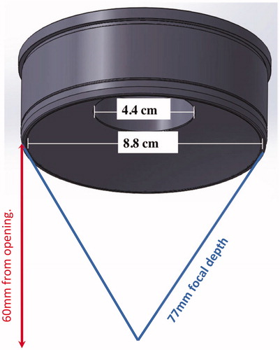
The acoustic source was a bowl-shaped transducer with four concentric annular rings functioning as the active elements (Neurolyser XR, FUSMobile, Alpharetta GA). Each ring was operated incoherently with 1 kHz separation between each element (1.000 MHz, 1.001 MHz, 1.002 MHz and 1.003 MHz, innermost to outermost rings) in order to operate in an incoherent mode. When waves interact in a coherent mode, their amplitudes are added. In incoherent mode, intensities are added. Two waves at different frequencies are incoherent, whatever the frequency difference Δf is. The specific value of Δf defines the time needed to repeat the pattern: T = 1/Δf. It has been reported that thermal diffusion can be neglected for pulses shorter than 1 ms[Citation33]. We decided to match our pattern with a 1 ms period so that acoustical and thermal effect are decoupled. This corresponds to a 1 kHz frequency difference between the transducers.
The outer diameter was 88 mm and inner diameter was 44 mm (). The radius of curvature of the transducer was 77 mm. The circular opening in the center was created to allow X-ray based targeting (see next section).
Figure 1. Schematic of transducer geometry.
In vivo experiments
Following approval for animal study, two pigs were sonicated at Lahav CRO (Israel) using the Neurolyser XR in a mock scenario of facet treatment.
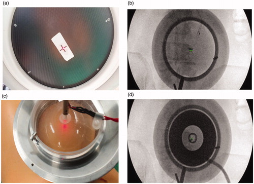
Targeting was done using fluoroscopy to identify the target (the anatomical location of the MBN). Once the target was identified, an aluminum cradle holding the transducer was aligned to the target using optical and radiological markers placed at the center of the fluoroscopy intensifier and on the patient’s skin (). The skin marker was placed by overlapping it with the fluoroscopy central marker and the anatomical target as seen on the X-ray image ().
Figure 2. (A–B) Alignment of the aluminum cradle to the target using optical and radiological markers placed at the center of the fluoroscopy intensifier and on the patient skin. (C–D) Anatomical targeting as seen on the X-ray image.
At each location pigs were treated with a 50 s duration at approximately 40 W (total acoustic energy of 2000 J). The transducer was calibrated using radiation force balance (RFB) measurement to assess the acoustic power used for each pigs. A high frequency acoustic absorber plate (AptFlex series, Precision Acoustics, UK) was attached to the bottom of a water bath. The water bath was placed on an electrical balance with the transducer connected to a mechanical arm and positioned directly above the absorber. The acoustic power was found to be 40.5 and 43 acoustic watts for pigs 1 and 2 respectively. Total energy delivered was 2025 and 2150 acoustic joules, respectively. For each pig we created three lesions at the junction of the transvers process and facet process, which is the anatomical location of the MBN on the dorsal aspects of L2, L3 and L4 vertebras on the right side.
Following the Neurolyser XR procedure, pigs were follow-up, by an animal technician and a veterinarian. During these visits, the pigs were monitored for general behavior, intake of food and water and any neurological deficits.
One week following the procedure, the pigs were sacrificed, the treated tissue was excised, and the lesions in the soft tissue and bone were evaluated for macro and micro histopathology. The size of the lesions was measured and used to scale the simulation parameters until the simulation results were close to experimental results.
Simulation model
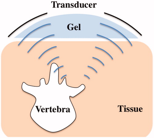
The shape of the bone was extracted from a stack of computed tomography (CT) images from the pigs used in the in vivo study (). Image acquisition of excised vertebras was done on a Philips MX8000 IDT 16 CT with image thickness of 0.8 mm and 0.4 mm space between slices. The transducer and bone were discretized as an isometric 3 D grid with grid size of 0.375 mm. The target was the junction of the transverse and facet process on the posterior aspect of the porcine vertebra. In order to better fit with the experimental treatment geometry, which was done at 15 degrees to sagittal plane [Citation34], the transducer was also tilted 15 degrees incident to the facet joint. Finally, the whole geometry was modeled, including soft tissues and the coupling of the transducer via a gelatin pad ().
Figure 3. CT images were loaded into MATLAB to generate the bone geometry for simulation.
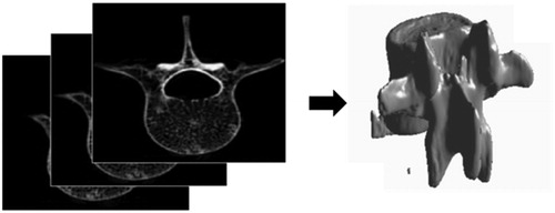
Figure 4. Schematic of all components for simulating FUS treatment.
Acoustic modeling
Acoustic simulations were performed using k-Wave 1.2.1 simulation toolbox in MATLAB. Acoustic propagation was simulated using k-Wave’s k-space time-domain model through a 3 D heterogeneous medium. The GPU-accelerated solver was used with a TITAN Xp (Nvidia).
k-Wave utilizes the k-space pseudospectral method solving the system of coupled acoustic equations. It combines the spectral calculation of spatial derivatives (using the Fourier collocation method) with a temporal propagator expressed in the spatial frequency domain (k-space). A Fourier series is fit to all the grid points and the fast Fourier transform (FFT) is used to calculate the amplitudes of the Fourier components. The temporal derivatives are solved using finite differences. Specific detail on the pseudospectral implementation of the wave equations can be found in [Citation35].
Each ring of the transducer was operated at 1 kHz separation (referred as “incoherent mode” in the rest of the article), which would require a minimum 1 ms sonication duration to calculate the RMS pressure. The corresponding number of time steps in order to simulate the correct focal spot size could not fit into our available memory. Thus, we simulated 4 kHz separation that allowed for shorter simulations (0.25 ms) but gave the same spot size (see Supplementary figure 1). For comparison, the transducer was also simulated with all rings operated coherently, at the same 1 MHz frequency (referred as ‘coherent mode’ in the rest of the article).
Skin, fat and muscle tissue could not be segmented on the CT scans. Soft tissues were thus modeled as homogeneous tissues as was done in [Citation36]. summarizes the acoustical properties of the tissues and gel that were used in the simulation.
Table 1. Thermal and acoustical properties of tissues.
The absorption of the bone varies considerably in the literature [Citation41–45]. The absorption was tested in the 8 − 90 dB/cm/MHz range, and the results were compared to measurements in pigs. As with the pig bone, the human bone was imaged in CT and imported into MATLAB to generate a geometrical model for simulation. The bone, tissue, and gel were simulated as homogenous regions ().
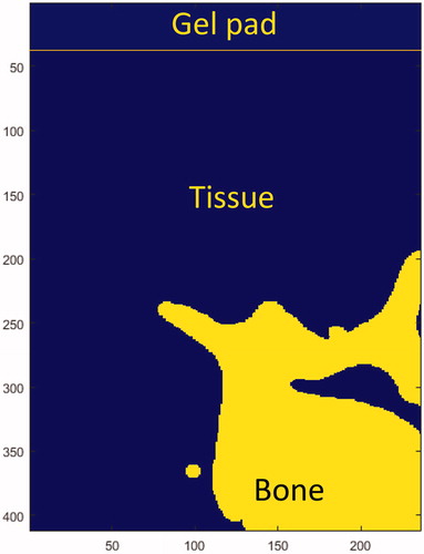
Figure 5. Slice of the 3 D anatomy used in simulations.
Thermal modeling
Thermal simulations were performed with k-Wave’s solver of the 3 D Pennes’ bioheat equation [Citation46]–the general form given by:
Where
is the density of tissue,
is the specific heat of tissue,
is the temperature of tissue,
is the thermal conductivity of tissue,
is the density of blood,
is the specific heat of blood,
is the perfusion rate of blood,
is the arterial temperature.
is the volume rate of heat deposition and calculated from
the absorption coefficient in Np/m,
is the speed of sound in tissue, and
the RMS pressure.
The resulting RMS pressure field of the acoustic model was used as the input heat source for the thermal simulation. summarizes the thermal properties of the tissues and gel pad that were used in the simulation.
In order to assess the effect of the thermal rise to tissues, we used the concept of thermal dose [Citation47]. The thermal dose is the thermal equivalent of the radiation dose used in radiotherapy [Citation48]. This has units of cumulative equivalent minutes at 43 °C (CEM43), and allows conversion of any temperature/time (T/t) combination to the equivalent time for which the reference temperature of 43 °C must be applied to obtain the same level of thermal damage:
The definition of the thermal isoeffective dose formalizes the idea that two different temperatures applied over different time intervals can have the same biological effect on a given tissue. A threshold lesion map was generated where the CEM43 exceeded 240 [Citation49]. The dimensions of the resulting lesion were measured at the acoustic focus.
Simulation of clinical scenarios in humans
Following the calibration of the bone absorption, multiple clinical scenarios were simulated to investigate the safety of the device. Three energy levels, 1000 J, 1500 J, and 2000 J, (50 s 20w, 50 s 30w, 50 s 40w), were simulated. For each energy level we simulated lesions at different depths (57-97mm) to represent patients with different amounts of fat and tissue between the skin and bone. For 2000 J we tested a secondary scenario where the energy was spread out over two 1000 J sonications with a 5 s cool down between sonications, (50 s 20w + 50 s 20w).
Results
Simulation of coherent and incoherent
The transducer was simulated and the spot size at −6 dB was characterized for the two operating modes. In a non-absorbing medium (water), the spot size was found to be 14 × 1.6 mm and 52 × 1.6 mm for coherent and incoherent mode, respectively. In an absorbing medium (tissue), the spot size was found to be 13 × 1.6 mm and 47 × 1.6 mm for coherent and incoherent mode, respectively. The simulated spots displayed as the ratio of the RMS pressure over the RMS pressure at the source (pressure gain) at are shown in . The acoustic pressure field with bone is displayed in .
Figure 6. (A) Profile through the focal spot of the pressure field for incoherent and coherent mode. Slice through the center of the focal spot of the pressure field for (B) incoherent and (C) coherent mode for water. Color bar represents pressure gain (ratio of the pressure at the acoustic focus to the pressure at the transducer’s surface).
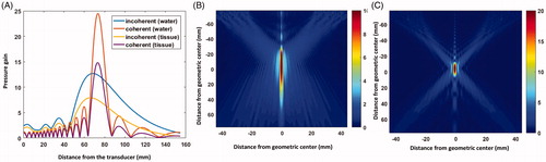
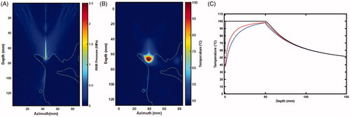
Figure 7. Slice of the 3 D anatomy used in simulations. (A) Outline of bone with respect to the RMS pressure. Thermal rise for a 50 s sonication at 30 W : 2 D map (B) and time curves (C) of the temperature at the surface of the bone (black), 0.75 mm (blue) and 1.125 mm (red) away in tissue.
Porcine follow up and bioheat histology
All pigs retained normal physical examinations with no limping, no neurological deficits, no lack of energy, and no loss of appetite throughout the follow-up period.
The overall lesions mean width was 15.2 ± 1.1 mm and 15.8 ± 3.4 mm and mean length into the soft tissue was 9.8 ± 3.7 mm and 8.0 ± 4.3 mm per histology (N = 6) and gross pathology (N = 5) measurements ().
When averaging histology and gross pathology measurements (N = 11), the overall mean width was 15.5 ± 2.5 mm and mean length into the soft tissue was 8.8 ± 4.0.
Porcine bioheat simulations
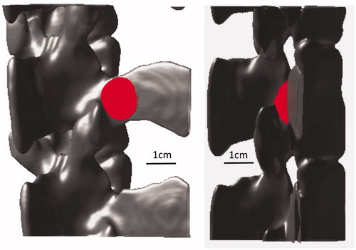
displays the 3 D simulated lesions, corresponding to the volume for which the CEM is greater than 240. The location of the simulated lesion corresponds to the anatomical expected location of the MBN. There was no indication of any secondary/off-target lesions. Next, the lesion dimensions were characterized as a function of bone absorption (): the width of the lesion (blue line) and the out of the bone lesion (red line) increase with the bone absorption, while the lesion in the bone gets thinner when absorption increases. This was compared to the pathology measurements and an absorption coefficient of 30 dB/cm/MHz was determined to match best the pathology results. At this absorption, we simulated the lesion size at the experimental energy level of 2000 J delivered over 50 s at 80 mm bone depth. The size of the lesion was found to be 15.75 mm wide, 5.63 mm deep into the bone, and protruding 6.75 mm out of the bone. Compared to the experimental size of the lesion out of the bone, it corresponds to a 5.7% error in width and 13.5% in length.
Figure 8. Gross pathology of one of the lesions.
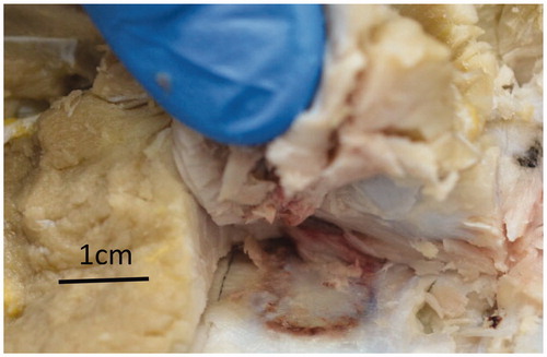
Figure 9. Two 3 D views of the pig bone and simulated lesion showing that the lesion is at the facet joint.
Human bioheat simulations
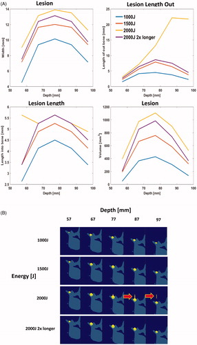
No off-target lesions were seen for energies 1000–1500 J (). At 2000 J, there were secondary lesions ( arrows). In shallow bone (<67 mm), there is secondary heating on the bone probably due to intersection with the beam path. In deep bone (>77 mm), there may be direct heating of the tissue. Largest lesion was generated at a peak depth of approximately 70–80 mm.
Figure 10. (A) Characterization of lesion dimensions as a function of bone absorption. The red line corresponds to lesion outside of the bone, yellow line corresponds to lesion in the bone, and blue line represents the width of the lesion. (B) 2 D slice through the bone and lesion, simulated with an absorption of 30 dB/cm, bone depth of 80 mm, with 2000 J energy delivered over 50 s.
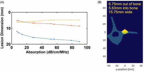
Figure 11. (A) Lesion dimensions as a as a function of depth for various energy levels. (B) Images of lesions and bone for the scenarios tested. Arrows point out conditions with secondary lesions. Because of secondary lesions we tested 2× longer sonication duration (on next page).
Discussion
The primary and critical concern with FUS applied to the neural tissue ablation such as MBN is the possibility of unintended damage to adjacent spinal cord and nerves. From our simulations, this is unlikely to occur due to the strong attenuation of the vertebra. Very little energy penetrates deep into the bone as demonstrated in our simulations and pathological evaluation of the bone in the animal study. The lesion was confined to the dorsal edge of the vertebra and is far from the spinal root ().
In the literature, the absorption coefficient in bone ranges approximately ∼2–20 dB/cm/MHz depending on the type of bone and species [Citation41–45]. Our simulations best match a bone with very high absorption coefficient of 30 dB/cm/MHz. This might be because our simulation does not include phenomena such as shear waves. As a first approximation, the bone was considered here to behave like a fluid, as is done by many groups when modeling the propagation of a wavefront in the skull for transcranial brain therapy [Citation50–54]. Nevertheless, cancellous bone supports both compressive and shear waves [Citation55]. Shear wave absorption in bone is two times higher than longitudinal absorption [Citation43]. In our model, an effective absorption coefficient was used, encompassing both shear and longitudinal absorption.
Cavitation and gas generation can also occur if temperature reaches past a temperature of 100 °C. Bubbles generated by this effect can shield the post-focal area from acoustic energy [Citation56], thus limiting the penetration into bone and enhancing heating locally due cavitation and scatter. We did not directly simulate the bio-effects caused by formation of bubble clouds and cavitation. Others have attempted to address this using different approaches. Moriyama et al. [Citation57] found an effective absorption coefficient with cavitation using least squares fitting and used that value in their simulations. Wang et al. [Citation58] used the Gilmore model [Citation59] to account for enhanced heating due to bubble oscillation. Grisey et al. [Citation60] simulated deposition patterns due to boiling and presented an approach for changing the pattern when the temperature reaches a threshold. Our approach is closest to the fitting approach; however, the absorption was chosen based on the observed lesion size from the pig studies. Although we do not directly simulate the shielding and scatter effects of bubbles, our simulations represent a worst-case scenario without shielding. Even in this case, we do not see undesired bio-effects such as heating of unwanted tissue outsize the focal region.
Based on RFB measurements, our device’s electronics were non-linear at high power and thus had to be calibrated. The calibration was performed at 60% and 100% power of the system. After calibration we were able to calculate the correct acoustic energy delivered during the experiments and a nominal value of 2000 acoustic joules was simulated. In clinical practice the system will be delivered pre-calibrated.
After tuning our simulation parameters, we simulated several clinical scenarios that will be used in practice, primarily 1000–2000 J of energy delivered over the course of 50 s. These procedure parameters were determined based on desired treatment times in clinical practice. We found that 1000 J and 1500 J led to a large enough lesion (≥5 mm) formation to ablate the desire neural tissue area. The simulation depth for the MB used in this study was 57–97 mm which is consistent with the report of over 100 CT scans where 97 mm of penetration would be adequate to treat 90% of the patient population [Citation61]. 2000 J for a single sonication was too high as it may potentially cause a secondary lesion in tissue according to our simulation. However, there is often convective cooling caused by perfusion which can be a function of temperature. These dynamics were not captured in our current simulation and will be investigated in future experiments. We were able to create a bigger lesion with 2000 J confined to the targeted area, by spreading it over two sonications (). The current system automatically shuts off after 60 s so we simulated a cooling period of 5 s in between sonications. This allows for enough cooling to prevent direct heating of the tissue. Secondary lesions caused by shallow bone can be addressed in practice by using a thicker gel pad so the beam path does not intersect with un-targeted bone.
Conclusion
The simulations presented in this study provide numerical analysis for the ablation of neural tissue including the MBN and secondary evidence of the safety of HIFU for targeting the lumbar region of the spine. The study had some limitations which warrant future investigation to fully understand the potential bio-effects such as the effects of shear waves and cavitation of bubble clouds. However, the simulations present a first order approximation that will be improved in future investigations.
Supplemental Material
Download PDF (208.4 KB)Disclosure statement
AH and RA are the founders of FUSMobile. JFA is a member of the scientific advisory board of FUSMobile and holds ordinary options of the company. JC was paid as an advisor to FUSMobile. SDL holds shares and ordinary options in FUSMobile. JP and YS did not receive remuneration for contribution to this study but their institution, McGill University, did receive payment for participation in follow up studies. MG is involved in other research projects funded by FUSMobile.
References
- Patient Education Resources. AAPM. https://painmed.org/clinician-resources/patient-education-resources. (consulté le mars 20, 2020).
- Radiofrequency Ablation Devices Market by Product, Geography and Forecast to 2027 - TMR. https://www.transparencymarketresearch.com/radiofrequency-ablation-devices.html. (consulté le mars 20, 2020).
- Manchukonda R, Manchikanti KN, Cash KA, et al. Facet joint pain in chronic spinal pain: an evaluation of prevalence and false-positive rate of diagnostic blocks. J Spinal Disord Tech. 2007;20(7):539–545.
- Cohen SP, Williams KA, Kurihara C, et al. Multicenter, randomized, comparative cost-effectiveness study comparing 0, 1, and 2 diagnostic medial branch (facet joint nerve) block treatment paradigms before lumbar facet radiofrequency denervation. Anesthesiology. 2010;113(2):395–405.
- Burnham RS, Holitski S, et, Dinu I. A prospective outcome study on the effects of facet joint radiofrequency denervation on pain, analgesic intake, disability, satisfaction, cost, and employment. Arch Phys Med Rehabil. 2009;90(2):201–205.
- Cohen SP, Raja SN. Pathogenesis, diagnosis, and treatment of lumbar zygapophysial (facet) joint pain. Anesthesiology. 2007;106(3):591–614.
- Boswell MV, Colson JD, Sehgal N, et al. A systematic review of therapeutic facet joint interventions in chronic spinal pain. Pain Physician. 2007;10(1):229–253.
- Nath S, Nath CA, Pettersson K. Percutaneous lumbar zygapophysial (Facet) joint neurotomy using radiofrequency current, in the management of chronic low back pain: a randomized double-blind trial. Spine. 2008;33(12):1291–1297.
- Haar GT, Coussios C. High intensity focused ultrasound: physical principles and devices. Int J Hyperthermia. 2007;23(2):89–104.
- Dick EA, Gedroyc WMW. ExAblate magnetic resonance-guided focused ultrasound system in multiple body applications. Expert Rev Med Devices. 2010;7(5):589–597.
- Foley JL, Eames M, Snell J, et al. Image-guided focused ultrasound: state of the technology and the challenges that lie ahead. Imaging Med. 2013;5(4):357–370.
- Tyshlek D, Aubry J-F, Ter Haar G, et al. Focused ultrasound development and clinical adoption: 2013 update on the growth of the field. J Ther Ultrasound. 2014;2(2):2.
- Bradley WG. MR-guided focused ultrasound: a potentially disruptive technology. J Am Coll Radiol. 2009;6(7):510–513.
- Brown MRD, Farquhar-Smith P, Williams JE, et al. The use of high-intensity focused ultrasound as a novel treatment for painful conditions-a description and narrative review of the literature. Br J Anaesth. 2015;115(4):520–530.
- Harnof S, Zibly Z, Shay L, et al. Magnetic resonance-guided focused ultrasound treatment of facet joint pain: summary of preclinical phase. J Ther Ultrasound. 2014;2:9.
- Weeks EM, Platt MW, et, Gedroyc W. MRI-guided focused ultrasound (MRgFUS) to treat facet joint osteoarthritis low back pain-case series of an innovative new technique. Eur Radiol. 2012;22(12):2822–2835.
- Liberman B, Gianfelice D, Inbar Y, et al. Pain palliation in patients with bone metastases using MR-guided focused ultrasound surgery: a multicenter study. Ann Surg Oncol. 2009;16(1):140–146.
- Hurwitz MD, et al. Magnetic resonance-guided focused ultrasound for patients with painful bone metastases: phase III trial results. J Natl Cancer Inst. 2014;106(5):10.
- Huisman M, ter Haar G, Napoli A, et al. International consensus on use of focused ultrasound for painful bone metastases: current status and future directions. Int J Hyperthermia. 2015;31(3):251–259.
- Izumi M, et al. MR-guided focused ultrasound for the novel and innovative management of osteoarthritic knee pain. BMC Musculoskelet Disord. 2013;14:267.
- Napoli A, Mastantuono M, Cavallo Marincola B, et al. Osteoid osteoma: MR-guided focused ultrasound for entirely noninvasive treatment. Radiology. 2013;267(2):514–521.
- Aubry J-F. High-intensity therapeutic ultrasound: metrological requirements versus clinical usage. Metrologia. 2012;49(5):S259–S266.
- Waldman DL. Interventional ultrasound, an issue of ultrasound clinics, E-book. Amsterdam: Elsevier Health Sciences; 2013.
- Aubry J-F, Pauly KB, Moonen C, et al. The road to clinical use of high-intensity focused ultrasound for liver cancer: technical and clinical consensus. J Ther Ultrasound. 2013;1(1):13.
- Vidal-Jove J, Perich E, del Castillo MA. Ultrasound Guided High Intensity Focused Ultrasound for malignant tumors: the Spanish experience of survival advantage in stage III and IV pancreatic cancer. Ultrason Sonochem. 2015;27:703–706.
- Xiong LL, Hwang JH, Huang XB, et al. Early clinical experience using high intensity focused ultrasound for palliation of inoperable pancreatic cancer. JOP J Pancreas. 2009;10(2):123–129.
- Wu F, Wang Z-B, Cao Y-D, et al. A randomised clinical trial of high-intensity focused ultrasound ablation for the treatment of patients with localised breast cancer. Br J Cancer. 2003;89(12):2227–2233.
- Poissonnier L, Chapelon J-Y, Rouvière O, et al. Control of prostate cancer by transrectal HIFU in 227 patients. Eur Urol. 2007;51(2):381–387.
- Dickinson L, Arya M, Afzal N, et al. Medium-term outcomes after whole-gland high-intensity focused ultrasound for the treatment of nonmetastatic prostate cancer from a multicentre registry cohort. Eur Urol. 2016;70(4):668–674.
- Elias WJ, Huss D, Voss T, et al. A pilot study of focused ultrasound thalamotomy for essential tremor. N Engl J Med. 2013;369(7):640–648.
- Lipsman N, Schwartz ML, Huang Y, et al. MR-guided focused ultrasound thalamotomy for essential tremor: a proof-of-concept study. Lancet Neurol. 2013;12(5):462–468.
- Warden SJ, Bennell KL, McMeeken JM, et al. Can conventional therapeutic ultrasound units be used to accelerate fracture repair? Phys Ther Rev. 1999;4(2):117–126.
- Jiao J, Guo Z. Bio-heat transfer in a model skin subject to a train of short pulse irradiation. International Mechanical Engineering Congress and Exposition; 2008 Oct 31–Nov 6; Boston, MA.
- Kaye EA, Monette S, Srimathveeravalli G, et al. MRI-guided focused ultrasound ablation of lumbar medial branch nerve: feasibility and safety study in a Swine Model. Int J Hyperthermia. 2016;32(7):786–794.
- Treeby BE, et, Cox BT. k-Wave: MATLAB toolbox for the simulation and reconstruction of photoacoustic wave fields. J Biomed Opt. 2010;15(2):021314.
- Barnat N, Grisey A, Lecuelle B, et al. Noninvasive vascular occlusion with HIFU for venous insufficiency treatment: preclinical feasibility experience in rabbits. Phys Med Biol. 2019;64(2):025003.
- Treeby BE, et, Saratoon T. The contribution of shear wave absorption to ultrasound heating in bones: coupled elastic and thermal modeling. In: 2015 IEEE International Ultrasonics Symposium (IUS); 2015 Oct. p. 1–4.
- Parker Laboratories, Fairfield (NJ). Technical Data Sheet: AQUAFLEX ultrasound gel pad; 2013.
- Etheridge ML, Choi J, Ramadhyani S, et al. Methods for characterizing convective cryoprobe heat transfer in ultrasound gel phantoms. J Biomech Eng. 2013;135(2):021002–02100210.
- Scott SJ, Salgaonkar V, Prakash P, et al. Interstitial ultrasound ablation of vertebral and paraspinal tumours: parametric and patient-specific simulations. Int J Hyperth Off J Eur Soc Hyperthermic Oncol North Am Hyperth Group. 2014;30(4):228–244.
- Sasso M, Haïat G, Yamato Y, et al. Frequency dependence of ultrasonic attenuation in bovine cortical bone: an in vitro study. Ultrasound Med Biol. 2007;33(12):1933–1942.
- Ammi AY, Mast TD, Huang I-H, et al. Characterization of ultrasound propagation through ex-vivo human temporal bone. Ultrasound Med Biol. 2008;34(10):1578–1589.
- Pinton G, Aubry J-F, Bossy E, et al. Attenuation, scattering, and absorption of ultrasound in the skull bone. Med Phys. 2012;39(1):299–307.
- Pichardo S, Sin VW, Hynynen K. Multi-frequency characterization of the speed of sound and attenuation coefficient for longitudinal transmission of freshly excised human skulls. Phys Med Biol. 2011;56(1):219–250.
- Duck FA. Physical properties of tissues: a comprehensive reference book. Cambridge, MA: Academic Press; 2013.
- Pennes HH. Analysis of tissue and arterial blood temperatures in the resting human forearm. J Appl Physiol. 1948;1(2):93–122.
- Sapareto SA, Dewey WC. Thermal dose determination in cancer therapy. Int J Radiat Oncol. 1984;10(6):787–800.
- Schlesinger D, Lee M, Ter Haar G, et al. Equivalence of cell survival data for radiation dose and thermal dose in ablative treatments: analysis applied to essential tremor thalamotomy by focused ultrasound and gamma knife. Int J Hyperthermia. 2017;33(4):401–410.
- Yarmolenko PS, Moon EJ, Landon C, et al. Thresholds for thermal damage to normal tissues: an update. Int J Hyperthermia. 2011;27(4):320–343.
- Constans C, Mateo P, Tanter M, et al. Potential impact of thermal effects during ultrasonic neurostimulation: retrospective numerical estimation of temperature elevation in seven rodent setups. Phys Med Biol. 2018;63(2):025003.
- Maimbourg G, Houdouin A, Deffieux T, et al. 3D-printed adaptive acoustic lens as a disruptive technology for transcranial ultrasound therapy using single-element transducers. Phys Med Biol. 2018;63(2):025026.
- Marsac L, Chauvet D, La Greca R, et al. Ex vivo optimisation of a heterogeneous speed of sound model of the human skull for non-invasive transcranial focused ultrasound at 1 MHz. Int J Hyperthermia. 2020;33(6):1. https://www.tandfonline.com/doi/full/10.1080/02656736.2017.1295322
- Robertson JLB, Cox BT, Jaros J, et al. Accurate simulation of transcranial ultrasound propagation for ultrasonic neuromodulation and stimulation. J Acoust Soc Am. 2017;141(3):1726–1738.
- Yin X, Hynynen K. A numerical study of transcranial focused ultrasound beam propagation at low frequency. Phys Med Biol. 2005;50(8):1821–1836.
- Pulkkinen A, Werner B, Martin E, et al. Numerical simulations of clinical focused ultrasound functional neurosurgery. Phys Med Biol. 2014;59(7):1679–1700.
- Meaney PM, Cahill MD, ter Haar GR. The intensity dependence of lesion position shift during focused ultrasound surgery. Ultrasound Med Biol. 2000;26(3):441–450.
- Moriyama T, Yoshizawa S, Umemura S. Thermal simulation of cavitation-enhanced ultrasonic heating verified with tissue-mimicking gel. Jpn J Appl Phys. 2012;51(7S):07GF27.
- Wang M, Lei Y, Zhou Y. High-intensity focused ultrasound (HIFU) ablation by the frequency chirps: enhanced thermal field and cavitation at the focus. Ultrasonics. 2019;91:134–149.
- Gilmore FR. The growth or collapse of a spherical bubble in a viscous compressible liquid. California Institute ofTechnology, CA: Hydrodynamics Laboratory; 1952.
- Grisey A, Yon S, Letort V, et al. Simulation of high-intensity focused ultrasound lesions in presence of boiling. J Ther Ultrasound. 2016;4(1):11.
- Zwiebel H, Aginsky R, Hananel A, et al. In vivo measurements of medical branch nerve depth and adjacent osseous structrues for ablation of facet related back pain: predictors for patient candidacy. Accepted for Publication, NASSJ August 2020.