
 ?Mathematical formulae have been encoded as MathML and are displayed in this HTML version using MathJax in order to improve their display. Uncheck the box to turn MathJax off. This feature requires Javascript. Click on a formula to zoom.
Abstract
Purpose
The ExAblate body MRgFUS system requires advanced beamforming strategies for volumetric hyperthermia. This study aims to develop and evaluate electronic beam steering, multi-focal patterns, and sector vortex beamforming approaches in conjunction with partial array activation using an acoustic and biothermal simulation framework along with phantom experiments.
Methods
The simulation framework was developed to calculate the 3D acoustic intensity and temperature distribution resulting from various beamforming and scanning strategies. A treatment cell electronically sweeping a single focus was implemented and evaluated in phantom experiments. The acoustic and thermal focal size of vortex beam propagation was quantified according to the vortex modes, number of active array elements, and focal depth.
Results
Turning off a percentage of the outer array to increase the f-number increased the focal size with a decrease in focal gain. 60% active elements allowed generating a sonication cell with an off-axis of 10 mm. The vortex mode number 4 with 60% active elements resulted in a larger heating volume than using the full array. Volumetric hyperthermia in the phantom was evaluated with the vortex mode 4 and respectively performed with 100% and 80% active elements. MR thermometry demonstrated that the volumes were found to be 18.8 and 29.7 cm3, respectively, with 80% array activation producing 1.58 times larger volume than the full array.
Conclusions
This study demonstrated that both electronic beam steering and sector vortex beamforming approaches in conjunction with partial array activation could generate large volume heating for HT delivery using the ExAblate body array.
1. Introduction
Hyperthermia (HT) therapy is a complementary cancer treatment technique, with demonstrated potential to enhance drug delivery and/or sensitize tumors to radiation and chemotherapy by elevating target tissue temperature to 40–45 °C for 30–60 min [Citation1]. Previous clinical studies demonstrated that HT can improve local control and overall survival in patients with various types of malignant tumors such as breast cancer, prostate cancer, cervical cancers, melanoma, sarcomas, and head/neck cancer [Citation2,Citation3]. Recent studies have also demonstrated that HT can provoke an immune response through mechanisms, such as cell damage, heat shock protein activation, immune cell activation, and changes in the tumor vasculature [Citation4–7].
Currently, clinical hyperthermia is delivered using a number of modalities and technologies, including RF, microwave, and ultrasound energy, capable of treating superficial and deep tumor targets [Citation8–10]. These techniques allow delivering HT to deep-tissue tumors, but still, require effective large volume targeting with more precise heat deposition. Past clinical efforts demonstrated that extracorporeal scanned focused ultrasound systems could deliver precise spatial selectivity and dynamic controlled hyperthermia to superficial and deep tissue sites, albeit with limited invasive thermometry [Citation11]. To achieve safety, HT requires maintenance of tissue temperature within a narrow range and delivery of a therapeutic thermal dose. This necessitates spatially controllable heat delivery and adequate temperature monitoring.
Magnetic resonance imaging (MRI) features superior soft-tissue contrast and allows for non-invasive temperature measurement. MRI-guided HT allows real-time monitoring of therapy delivery for the precise control of HT heating to maintain target tissue temperature as well as treatment verification [Citation12]. MR-guided focused ultrasound (MRgFUS) systems have been developed for noninvasive heat delivery with a high degree of spatial selectivity and dynamic control. With many inherent advantages, MRgFUS systems have been employed for thermal ablation treatment of sites such as the brain, uterine fibroids, prostate, pancreas, and bone metastases [Citation13]. Although clinical MRgFUS systems were initially developed and approved for thermal ablation treatments, the platforms may technically be capable of delivering prolonged moderate heating required for HT deep within the body through software modifications.
Currently, the ExAblate and the Sonalleve are the two MR-guided FUS ablation systems with the largest installation worldwide [Citation14]. Recent investigations have developed methods to use the Sonalleve array (MRgFUS system) to deliver effective HT patterns. Mougenot et al. proposed using the overlap effect of nearby sonication points to achieve 3D volumetric HT [Citation15]. Partanen et al. investigated a multifoci sonication approach for HT delivery using the Profound (previously Philips) Sonalleve system, based on sparse phased array in-table transducers [Citation16]. Tillander, et al. developed an approach for simultaneous electronic beam steering and mechanical transducer steering. Multifocal sonications created a circular trajectory for small cells (18–58 mm) and the mechanical transducer steering allowed covering a larger volume [Citation17]. With this system, Chu et al. [Citation18] demonstrated the feasibility of MRgFUS-based HT for rectal cancer, and several studies [Citation19,Citation20] reported the potential benefits of MRgFUS-based HT for head and neck cancers.
The ExAblate body system (ExAblate 2000, InSightec, Haifa, Israel) has been FDA approved for thermal ablation treatment of uterine fibroids and bone metastases [Citation21,Citation22]. However, as far as the authors know, volumetric HT delivery with this system has not been studied, due to the system being designed specifically for ablation. The ExAblate body transducer is based on a sectored concentric-ring phased array design, which limits off-axis focusing and volume heating. Further, this constraint requires slower movement of the transducer for repositioning the focal zones in lieu of electronic steering. Hence, it is much important to cover large volumes as much as possible before moving the transducer. O’Neill et al. developed and optimized pulsed HIFU treatment procedures to improve the efficiency of pulsed HIFU sonication to large volumes using the ExAblate body system, by optimally selecting focal patterns and their sequencing for the efficient combination of electronic and mechanical steering [Citation23]. Although their approach resulted in larger volume treatment than a single focal spot, it only relied on multi-focal sonications with electronic steering and was optimized for enhancing the uptake of drugs, not HT delivery. Further study for efficient large volume heating in the ExAblate body system is still needed to achieve the larger volume heating efficiently.
The objective of this study was to investigate sonication strategies for larger volume heating using the sectored concentric-ring transducer array of the ExAblate body system. The array layout specific to the ExAblate system was modeled and used to calculate beam distributions for sequential focal steering, reduced partial array sonication patterns, and beamforming approaches for concentric ring sector vortex modes. Further, the temperature distributions achievable with these sonication strategies were evaluated in biothermal simulations and phantom experiments. Although no form of closed-loop control was implemented herein, this investigation introduced the types of beamforming techniques attainable for volumetric heating using the ExAblate body MRgFUS platform as a proof-of-principle study. Metrics of hyperthermic volume and dimensions were used to evaluate and compare the HT patterns possible for a single transducer position.
2. Materials and methods
2.1. ExAblate 2000 system and experimental control
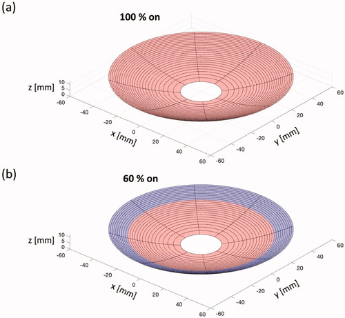
The ExAblate 2000 body system used in this study features a concentric-ring sectored-vortex phased array, with 3D positioning control and fluid coupling, integrated within the table for a 3T MRI scanner (GE Healthcare, Waukesha, WI). The transducer array is spherically curved (12 cm diameter, f-number = 1.3) and divided into 8 sectors and 26 concentric rings for a total of 208 independently phased elements (). The surface area of each element is evenly allocated as 54 mm2 and the applied power to each element can be independently controlled. The transducer frequency can be varied between 1 and 1.2 MHz, with 1 MHz typical operation. This phased array transducer is typically operated for thermal ablation using pre-set system configurations and limits, with electronic steering applied for focusing within a depth range of 60–220 mm, with off-axis steering of about 5 mm.
Figure 1. Schematic illustration of the ExAblate body phased-array transducer, with a spherically curved geometry including 8 sectors and 26 concentric rings, with equal surface area maintained for each of the 208 elements. Apart from phasing patterns, the illumination can be adjusted from 100% (a) to approximately 60% active elements (b) effectively reducing the aperture from 120 to 94.6 mm diameter.
In this study, we modified configuration files in the hardware control system to specify the amplitude and phase of each array element to test for the proposed sonication strategies and the system limit of off-axis distance (max. 5 mm off-axis) was lifted to investigate a method for a wider steering range. As described in more detail below, we explored two modes of beamforming with this array: (i) independent element phasing for positioning a single spot focus; and (ii) taking advantage of the spherically curved sectored-annular ring configuration, explore sector-vortex beamforming patterns with either a single on-axis focus (Mode 0) or annular spaced multi-focal patterns (Modes 2–4).
2.2. Electronic beam steering and sonication cell
A phased array transducer can be electronically steered by controlling the amplitude and phase of each element independently. This enables increased heating volumes by altering the ultrasound beam path. Using a geometric distance approach, a phase calculation for transverse and depth electronic steering on the ExAblate platform can be determined by calculating a distance from the center of each element to the desired focal position. The relative phase of the nth ring and the sth sector can be given by
(1)
(1)
where
is a distance from the center of the element (the nth ring and the sth sector) to the desired focal position,
is the modulus operator, and
is the acoustic wavelength in tissue [Citation24]. In this study,
of 1.5 mm (speed of sound 1540 m/s) is used for coupling water and tissue domains at the center frequency of 1 MHz.
In this study, transverse off-axis beam steering was performed to create a sonication cell, comprised of a set of four separate focal spots, forming corners of a square in a plane perpendicular to the beam propagation axis [Citation17]. Each spot was repeatedly sonicated for 500 ms sequentially with rapid electronic steering of the beam.
2.3. Sector-Vortex beamforming
The sectored-annular ring array configuration allows for sector-vortex beamforming which employs phase rotation with an acoustic intensity of the transducer axis, resulting in an annular-shaped energy ring on the cross-sectional plane, and a focal spot of a larger diameter [Citation25,Citation26]. In theory, a sector vortex array could support several phase distributions or modes by applying a linearly increasing phase offset to each of the sectors of the transducer with the phase values rotating one or more times throughout the circumference of the array. This number of rotations is referred to as the mode number (m) and cannot be larger than N/2 where N is the number of sectors. The phasing calculation of array elements can be implemented using the technique described by Fjield et al. [Citation24] The phase calculation from EquationEquation (1)(1)
(1) can be expanded to calculate the phase for vortex beamforming:
(2)
(2)
where m is vortex mode number and N is the number of sectors. Using EquationEquations (1)
(1)
(1) and Equation(2)
(2)
(2) , the annular focal distribution,
can be obtained by phasing array elements () [Citation25].
Figure 2. Conceptual diagram of sonications with electronic beam steering. (a) Electronic beam steering with a single focus along the z- and x-direction on an MR magnitude image. (b) Illustration of a sonication cell rapidly sweeping a single focal spot across four focal points. (c) top view of phase distribution steered along the z-axis and (d) phase distribution steered to 3 mm along the x-axis. (e, f) Top view of the phase distribution of transducer according to the vortex modes 2 and 4.
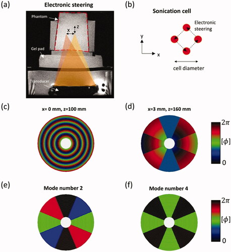
The ExAblate body transducer has 8 sectors that can be driven in 0–4 modes. A higher mode allows wider annular spaced multi-focal patterns on the cross-sectional plane, resulting in wider temperature distributions [Citation26]. This can be used to achieve a larger volume heating compared to a single focal spot (mode 0), commonly used for ablation treatments.
2.4. Full and partial array
The ExAblate body transducer is spherically curved to achieve a high energy density of the ultrasound beam at the focal spot. Theoretically, both the focal depth and aperture diameter can affect the length of the focal spot. If the focal depth is not variable, high-intensity gains and sharp focal spots are achieved with a larger diameter transducer, whereas a smaller diameter transducer allows for lower intensity gains and produces an elongated focal spot. To improve the performance of volumetric HT delivery, we considered methods of reducing the effective aperture size and increasing the f-number, that is, the ratio of the focal depth to the diameter of the transducer, by turning off a portion of the outer array as a means to increase the focal size with an expected decrease in focal gain (). Moreover, the transverse steering capability of the ExAblate array transducer was inherently limited due to the geometry of the array. Hence, turning off outer elements could lead to a less focused transducer with a higher steering range. In this study, the effect of partial active elements on the quality of the focus and the steering capability of the array was investigated.
2.5. Acoustic and biothermal simulation of array sonication strategies
The acoustic and biothermal simulation was developed and performed to characterize the size of the pressure fields in soft tissue and to evaluate the performance of the phased transducer. First, the complex pressure distribution from each array element was calculated as the following [Citation27]:
(3)
(3)
where the integration for the surface S of one array element,
is the density of the medium,
is the speed of sound,
is the normal velocity of the element surface,
is the wavelength,
is the wavenumber,
is the attenuation coefficient, and
is the distance from an element to the reference field point. Here the
of each element was calculated with the acoustic properties of water (). Then, the total pressure
can be acquired by summation of pressure
at a point in the reference plane [Citation27]:
(4)
(4)
Table 1. Parameters of acoustic and thermal tissue properties representative of general soft tissue used for the simulation studies [Citation36].
Where N is the number of array elements (N = 208), the amplitude is the relative amplitude at the nth element, and the phase
is calculated by EquationEquations (1)
(1)
(1) and Equation(2)
(2)
(2) . To achieve partial active elements,
could be set to 0 or 1 to deactivate or activate the element, respectively.
Second, since calculating 3D pressure distribution with the rectangular radiator method was prohibitively slow, the hybrid angular spectrum (HAS) method was applied to calculate the 3D propagation and resultant acoustic intensity distribution within the absorbing tissue medium [Citation28]. The HAS method has been demonstrated to rapidly calculate the complex pressure fields in an inhomogeneous 3D model with a short computation time. The at the tissue interface was used as the initial pressure pattern in the HAS method. The initial pressure field was encoded into a spectrum of traveling plane waves in the spatial-frequency domain. Propagation of the waves to the next plane was then estimated by the propagation transfer function [Citation28]. Finally, the 3D pressure distribution was calculated sequentially, plane-by-plane, assuming steady-state and linear wave propagation conditions.
To investigate temperature distributions of the proposed sonication strategies in general soft tissue, a finite element method solver of the Pennes Bioheat Equation (Comsol Multiphysics 5.5, Comsol, Inc., Burlington, MA, USA) was implemented to calculate steady-state temperature distributions with the maximum temperature set to 43 as appropriate for HT treatments. The Pennes Bioheat Equation [Citation29] can be defined by:
(5)
(5)
where
is the density of tissue (kg/m3),
is the specific heat capacity (J/
/kg),
is thermal conductivity (W/m/
),
is tissue temperature (
),
is blood temperature (
),
is blood perfusion (kg/m3/s), and
is the specific heat of blood (J/
/kg).
is the acoustic heat deposition in tissue (W/m3), which is defined as:
[6]
[6]
where c is a speed of sound [m/s],
is the acoustic absorption coefficient [m−1], p [Pa] is the complex pressure profile, and
[W/m2] is the acoustic intensity field that can be calculated by the pressure field assuming plane wave propagation of the ultrasound field. The magnitude of the spatial power deposition
is iteratively varied in a series of steady-state thermal simulations in order to apply the optimal power to achieve a maximum temperature of 43
2.6. Simulation and experimental protocols
2.6.1. Acoustic and biothermal simulation
To evaluate the focal gain according to the number of elements, a single focal pattern was simulated at the focal depth of 160 mm and with off-axis steering of 10 mm in the focal plane. This simulation was respectively performed with 100% and 60% active elements. The pressure field was calculated with the acoustic properties of homogeneous muscle tissue (). The pressure intensity obtained by the acoustic simulation was normalized.
Similarly, focal patterns for the vortex mode numbers 0, 2 and 4 were simulated at the focal depth of 160 mm in homogenous muscle tissue. The 3D acoustic pressure fields for the mode numbers were calculated and used in the biothermal simulation. In the case of mode number 4, the simulation was respectively performed with 60%, 80% and 100% active elements. All parameters for acoustic and thermal simulation were summarized in .
2.6.2. Phantom experiments
A soft tissue-mimicking phantom (InSightec, Haifa, Israel) was used for all experiments presented in this study (). This phantom was composed of solid gel with an acoustic absorption of 5.8 Np/m/MHz and speed of sound of 1538 m/s, with a diameter of 10.2 cm and a height of 12.7 cm [Citation23].
There were four experimental protocols used in this study:
Experiment 1 was performed to evaluate the performance of electronic beam steering with partial activation of array elements. A single focal spot was sonicated with the off-axis deflection of 10 mm in the focal plane for 50 s, with 60% and 100% active elements and acoustic power of 25 and 15 W, respectively.
Experiment 2 was designed to demonstrate the feasibility of multi-focal sonication cells with various off-axis distances for volumetric HT delivery. A set of four focal spots were set up with diameters of 12 mm and 20 mm and repeatedly sonicated at each spot for 500 ms () with rapid electronic steering. 60% active elements were activated for wide beam steering. Acoustic power of 20 and 25 W were respectively applied for sonication cells with diameters of 12 and 20 mm and lasted for 60 s.
Experiment 3 was to evaluate the performance of the sector vortex beamforming with partial elements in a soft tissue-mimicking phantom. Phasing patterns were loaded into the transducer control software. The 100%, 80%, and 60% of array elements were used for vortex beamforming with mode number 4. Sonications were, respectively, performed for the focal depth of 100, 130, and 160 mm. Different amounts of acoustic power were applied according to the mode numbers and focal depths as summarized in .
Experiment 4 was performed to investigate the steady-state HT distributions for the sector vortex beamforming in the phantom. Sonications with mode number 4 were implemented at the focal depth of 160 mm, for a duration of 10 mins. Experiments were similarly performed with 80% and 100% active elements, with acoustic powers of 7.8 and 5.6 W were respectively, for a duration of 10 min. In all experiments, the acoustic power and sonication time were manually selected to generate similar temperature elevations in the phantom when applying the partial array elements.
Table 2. Acoustic power and duration applied in experiment 3.
2.7. MRI temperature mapping
Proton resonance frequency shift (PRFS)-based MR thermometry was performed during heating to evaluate the sonication strategies. Images were acquired using a spoiled gradient-echo sequence with a body coil and were transferred to an external computer via a TCP/IP connection. MATLAB program (Matlab, MathWorks, Natick, MA) was used for the reconstruction of temperature maps once an image was acquired.
PRFS thermometry allows for real-time reconstruction and provides a high spatial resolution of temperature map. However, magnetic field drifts caused by gradient coil heating, patient’s motion, and time-varying phase changes may result in decreasing the accuracy of temperature measurement [Citation30]. To correct for phase changes caused by the field drifts, a compensation map was estimated by fitting polynomial functions to phase changes outside the focal region. Temperature errors induced by the field drifts were corrected by subtracting a compensation map in the PRFS calculation [Citation30,Citation31]. In this study, the temperature average within an ROI outside the focal region was used for the correction in the PRFS calculation, assuming that time-varying field drifts had homogeneous distributions in terms of the size of the phantom and the scanning time.
In experiment 1 and 2, MRI parameters included TR = 25.8 ms, TE = 12.9 ms, FOV = 280 mm 280 mm (experiment 1, 3 and 4)/320 mm
320 mm (experiment 2), Matrix = 256, thickness = 3 mm, and acquisition time = 3.3 s. A coronal slice was set at the focal depth in experiment 2 and an axial slice was set at the center of the transducer to cover the focal region in all experiments.
3. Results
3.1. Effect of beam steering on the acoustic and temperature distributions
shows the results of acoustic simulations and comparison to MR experiments for electronic beam steering. Normalized intensity distributions of a single focal spot steered to 10 mm off-axis in the focal plane were simulated, and respectively performed with 60% and 100% active elements. As a result, turning off the outer elements allowed steering the focus in transverse extent by 10 mm without generating any secondary lobes in comparison to 100% array which led to significant-high secondary lobes when the focus was steered 10 mm off the axis. These results were also observed in experiment 1. MR temperature maps indicated that sonications with 60% active elements allowed more steering of the focus without any significant secondary lobes as compared to those with 100% active elements.
Figure 3. Results of experiments 1 and 2 for sonications using the electronic beam steering. (a) Normalized acoustic intensity at (x–z) plane, obtained by 100% (top) and 60% (bottom) of array elements. MR temperature images for steering of 10 mm are shown when the maximum temperature of 3 is reached. (b) Temperature distributions with MR thermometry for a sonication cell rapidly sweeping a single focal spot. Sonication cells have a diameter ‘d’ of 12 and 20 mm at the focal depth of 130 mm (top) and 160 mm (bottom), respectively. The red dashed line indicates the boundary of the phantom: longitudinal slice (left) and transverse slice (right). A black solid line shows a boundary of an area above a temperature rise of 4
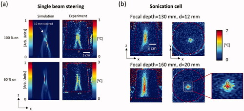
shows temperature distributions with MR thermometry for a sonication cell rapidly sweeping a single focal zone across four spot positions (experiment 2). MR temperature maps shown here were selected at the maximum temperature rise around 6.2 A boundary of an area above 4
(black line) was used for the evaluation of the heated volume. For a cell diameter of 20 mm, a volume was estimated to be 2.6 cm3, assuming an axisymmetric heated volume model. A lateral diameter of the boundary was measured 12.5 mm in experiment 2. Volume estimates according to the focal depths and cell diameters are summarized in .
Table 3. Summary of temperature metrics for the electronic beam steering (experiment 2) and the vortex beam mode (experiment 3) approaches.
3.2. Effect of sector-vortex beamforming
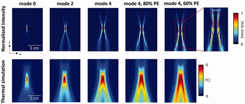
Acoustic and biothermal simulations for different phasing modes were performed in homogeneous muscle tissue. shows the simulated acoustic intensity fields and the steady-state HT distributions. Sonications with the vortex mode numbers 2 and 4 provided the focused pressure fields around the axis of the beam. For the analysis, a width of pressure fields was defined as the longest lateral distance between two peaks of intensity around the axis of the beam in modes 2 and 4 (top, right in ). In the simulated pressure fields, the maximum width of pressure fields was found to be approximately 22.5 mm lateral width when using 60% active elements and mode number 4. A width of normalized intensity fields was also closely related to the simulated temperature distributions. The simulated temperature distributions indicated that the heated volume was enlarged, for higher mode numbers and for the lower number of active elements.
Figure 4. Longitudinal normalized intensity fields (top row) and simulated temperature distributions (bottom row) for vortex beam modes 0, 2, and 4 as well as mode 4 with 80% and 60% partial elements (PE). The black solid line (top right) indicates a boundary of half of the maximum in the acoustic intensity and the red dashed line indicates the width of the boundary.
. shows the results of vortex beamforming in the phantom, with the mode number 4 and partial array elements (experiment 3). Temperature distributions with MR thermometry were shown when the hottest voxel in the phantom reached approximately 6.5 As predicted by the simulations, a heated volume was also found to increase with decreasing number of active elements and increasing the focal depth. summarizes the effects of partial array elements on the focal size with various focal depths. Using 60% active elements, the maximum heated volume was found to be 15.7 cm3. The length and width of an area above 4
were found approximately 46.2 mm and 15.4 mm, respectively.
Figure 5. Temperature distributions with MR thermometry for phantom experiments using the vortex beam modes 0 and 4 with 100%, 80%, and 60% partial elements (PE). Sonications were applied at the focal depth of 100 mm (top row), 130 mm (center row), and 160 mm (bottom row). Red dashed line indicates the position of phantom. A black solid line indicates an area of temperature rise above 4 (top right).
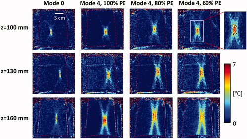
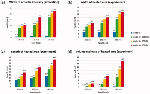
Figure 6. Effects of the vortex modes 0, 4 and partial array elements (PE) on lateral width in simulation (a) and experiment (b), axial length (experiment, c), as well as estimated volume (experiment, d), as measured for the area of temperature rise above 4
summarizes the size and dimension of heat depositions of the beam steering and vortex mode approaches in the phantom. The 4 contour areas were selected when the maximum temperature rise of 6
in order to estimate a volume where therapeutic HT (T
41
) can be produced. Increased power requirement due to partial elements was considered in some experiments and had a different time to reach a temperature rise of 6
A length-to-width ratio for the 4
contour areas was found to be lower sequentially for vortex mode 4 using 100% array elements, for mode 4 using 60% active elements, and for a sonication cell using the electronic steering.
3.3. Steady-state volumetric hyperthermia in the phantom
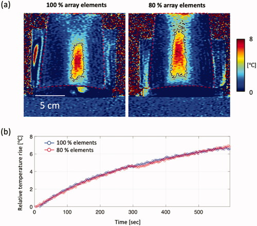
shows volumetric HT distributions in the phantom after prolonged heating with a slow temperature rise (experiment 4). Sonications were respectively performed with the mode number 4 and 80% and 100% active elements. Low power heating for 10 min was induced to mimic the steady-state HT distributions. Temperature measurements within an ROI (64 pixels at the center of the 4 contour) were averaged and plotted in (bottom). Both approached a steady-state around 6.9
after 600 s. The volumes of 18.8 cm3 and 29.7 cm3 were estimated by the 4
contour areas with 100% and 80% active elements, respectively. Heating with 80% active elements produced 1.58 times larger volume than that of 100% active elements.
Figure 7. Volumetric HT distributions in the phantom comparing 100% and 80% array activation. (a) Temperature maps at 600 s are shown and (b) time-dependent profiles of temperature measured in an ROI at the focus is plotted. A black solid line in the MR temperature map indicates an area for a temperature rise above 4
4. Discussion
In this study, we developed and evaluated sonication strategies for a sectored concentric ring array, designed for precise small volume thermal ablation, to generate HT over large target regions. We proposed the beam steering and vortex mode approaches integrated with the partial array elements. The method of turning off a percentage of the outer array could lead to an increase in the f-number and the focal size with a decrease in focal gain.
We have found that a less focused transducer allowed a wider range of off-axis steering (). Using the partial array activation, two different sizes of sonication cells with four focal spots were implemented to demonstrate the feasibility of various heating volumes. Heated regions were generated between the focal spots, forming a square shape in a transverse plane since the heat distributions of each focal spot were overlaid continuously. There were many control parameters such as the number of focal spots, cell size, heating time, and beam sweeping time. In this study, four focal spots were used to create a cell, based on the duration of each focal point (500 ms). The results for the sonication cell method demonstrated that 60% of array elements allowed off-axis distances between 5 and 10 mm along the focal depths between 100 and 160 mm while avoiding unwanted heat gain induced by the second lobes (). However, we did not evaluate the steering performance according to a wide range of f-numbers using the ExAblate body transducer. Further study is needed to investigate an optimized off-axis distance depending on the f-number.
Another approach presented in this study, varying phase distribution for the vortex modes resulted in increasing the volume size of the focal spot. Furthermore, the partial array activation allowed generating larger heating volumes in comparison to the use of full array elements. The result of experiment 4 demonstrated that an HT volume of 29.7 cm3 could be produced by 80% active elements at the focal depth of 160 mm in the phantom. In comparison with the sonication cell method, the vortex beam modes generated a significantly wider heating area in the phantom. A length-to-width ratio of the vortex mode approach was smaller than that of the sonication cell. Therefore, vortex-mode focal patterns could be more flexible to position heat to a target volume with various geometries [Citation16].
To control various sizes of the focal spot using the vortex modes, it is important to appropriately adjust sonication parameters such as mode numbers, focal depths, and a percentage partial array. The selection of these parameters should be considered according to the size of the target region, geometry, and acoustic and/or thermal properties. The acoustic and biothermal simulation framework presented here will support planning for appropriate choices. Future study should be explored for an optimal choice in patient-specific studies.
We have found in experiments 3 and 4 that the vortex beamforming would be suitable for HT, not ablation therapy. In experiment 3, heat patterns showed the ‘X’ shape due to the absence of time-dependent perfusion and short-term heating compared to HT (10 min). This can potentially generate further heating outside the target region. In contrast, homogenous heat distributions were found in experiment 4 due to HT heating (long-term heating). However, the heating patterns may be different in tissues with blood perfusion. Simulation results herein showed 60% of active elements generated elongated heat patterns outside the target region (). Further studies are needed to explore the choice of a proportion of active array elements for various tissue types. The results of simulations and experiments in this study showed the feasibility of volumetric HT heating in homogenous soft tissues when using 80% active elements with the vortex mode 4.
A limitation of our study is in using a small homogeneous tissue-mimicking phantom for our experiments. Future experiments will validate these sonication strategies in ex vivo muscle tissue without perfusion, as well as in animal models in vivo to investigate the performance of the vortex mode approach for delivering HT within heterogeneous tissues and blood perfusion. Another limitation of this study is that heating experiments were performed without demonstration of automatic feedback control to maintain longer duration mild HT heating. In order to investigate the HT heating patterns in tissues with blood perfusion, a closed-loop feedback control based upon MR temperature images [Citation32] should be implemented with the ExAblate body MRgFUS system. In this approach, the sonication power could be adjusted in real-time based on the temperature measurements within a region of interest. This could be achieved by enabling the pulsed sonication mode and varying the duty cycle of the ultrasound pulses. With the real-time power control, various feedback control strategies, such as multipoint [Citation33], proportional-integral-derivative (PID), and model predictive-based control [Citation34], could be integrated with the ExAblate system. For PID controller, its parameters may need to be optimized for different beam patterns, tissue targets, blood flow ranges, applied maximum power levels, focal depths, etc. [Citation35]. Furthermore, when applying the partial array elements, an HT controller may have different initial amounts of acoustic power due to its different heating efficiency. In experiment 4, two different acoustic powers were applied at 80% and 100% array elements, respectively, to achieve a similar temperature increase for 10 min.
Additionally, our experiments featured sonication from a single placement of the transducer. In future studies, the mechanical movement of the array between independent treatment zones will be integrated with the sonication strategies presented here in order to achieve larger volume heating. A previous study for the Sonalleve implemented a circular trajectory with seven sonication cells of 16 mm width [Citation17]. While it is difficult to directly compare these sonication strategies, we have demonstrated the cell width of 20 mm using rapid electronic beam steering with 60% of array elements. Moreover, the acoustic simulation for the vortex beamforming showed a focal area of 22.5 mm with mode 4 and 60% active array elements (). Although the heated volumes may vary with the acoustic and thermal properties of the tissue, these results suggest a potential to provide comparable hyperthermia volumes with mechanical transducer motion trajectories.
In the current clinical MRgFUS systems, a body imaging coil is commonly used for temperature monitoring. With a body coil, the appropriate spatial resolution should be chosen to satisfy the threshold of temperature accuracy and precision within the target region, as well as temporal resolution [Citation12]. In this study, a spoiled gradient-echo sequence with a body coil was also used to acquire PRFS data. In experiment 4, a standard deviation (SD) of temperature in the ROI was measured to be between 0.28 and 0.56
for 10 min (mean of SD = 0.39
), and the mean of temperature accuracy (mean absolute error) was approximately 0.31
This result was considered acceptable for temperature monitoring during hyperthermia treatments. Future studies in in vivo tissues will evaluate temperature precision and accuracy before and during the treatment. MRI parameters will be optimized to achieve optimal image quality, accuracy, and performance.
5. Conclusion
This study demonstrated the feasibility of large volume HT beam patterns using the ExAblate body system, which was not ideal for HT. Although the approach had been specifically studied for the ExAblate body system, the proposed methods were applicable to all other systems comprising of a concentric-ring sectored-vortex phased array. According to the results of experiments, both electronic beam steering and sector vortex beamforming approaches in conjunction with partial array elements were able to achieve various volume sizes of HT heating in the phantom. This technique could be used in the future with the mechanical movements for large volume HT treatments using the ExAblate 2000 body system.
Acknowledgments
The authors would like to thank Noam Maimon at InSightec, Inc. for assistance with developing the techniques.
Disclosure statement
No potential conflict of interest was reported by the author(s).
Additional information
Funding
References
- Datta NR, Ordóñez SG, Gaipl US, et al. Local hyperthermia combined with radiotherapy and-/or chemotherapy: recent advances and promises for the future. Cancer Treat Rev. 2015;41(9):742–753.
- Wust P, Hildebrandt B, Sreenivasa G, et al. Hyperthermia in combined treatment of cancer. Lancet Oncol. 2002;3(8):487–497.
- Fiorentini G, Sarti D, Gadaleta CD, et al. A narrative review of regional hyperthermia: updates from 2010 to 2019. Integr Cancer Ther. 2020;19:1534735420932648.
- Bandyopadhyay S, Quinn TJ, Scandiuzzi L, et al. Low-Intensity focused ultrasound induces reversal of tumor-induced T cell tolerance and prevents immune escape. J Immunol. 2016;196(4):1964–1976.
- Bastianpillai C, Petrides N, Shah T, et al. Harnessing the immunomodulatory effect of thermal and non-thermal ablative therapies for cancer treatment. Tumour Biol. 2015;36(12):9137–9146.
- Toraya-Brown S, Fiering S. Local tumour hyperthermia as immunotherapy for metastatic cancer. Int J Hyperthermia. 2014;30(8):531–539.
- Peeken JC, Vaupel P, Combs SE. Integrating hyperthermia into modern radiation oncology: what evidence is necessary? Front Oncol. 2017;7:132.
- Paulides MM, Dobsicek Trefna H, Curto S, et al. Recent technological advancements in radiofrequency- andmicrowave-mediated hyperthermia for enhancing drug delivery. Adv Drug Deliv Rev. 2020;163–164:3–18.
- Diederich CJ, Hynynen K. Ultrasound technology for hyperthermia. Ultrasound Med Biol. 1999;25(6):871–887.
- Zhu L, Altman MB, Laszlo A, et al. Ultrasound hyperthermia technology for radiosensitization. Ultrasound Med Biol. 2019;45(5):1025–1043.
- Shimm DS, Hynynen KH, Anhalt DP, et al. Scanned focussed ultrasound hyperthermia: initial clinical results. Int J Radiat Oncol Biol Phys. 1988;15(5):1203–1208.
- Feddersen TV, Hernandez-Tamames JA, Franckena M, et al. Clinical performance and future potential of magnetic resonance thermometry in hyperthermia. Cancers. 2020;13(1):31.
- Siedek F, Yeo SY, Heijman E, et al. Magnetic resonance-guided high-intensity focused ultrasound (MR-HIFU): technical background and overview of current clinical applications (part 1). Rofo. 2019;191(6):522–530.
- Schlesinger D, Benedict S, Diederich C, et al. MR-guided focused ultrasound surgery, present and future. Med Phys. 2013;40(8):080901.
- Mougenot C, Quesson B, Senneville BD, et al. Three-dimensional spatial and temporal temperature control with MR thermometry-guided focused ultrasound (MRgHIFU). Magn Reson Med. 2009;61(3):603–614.
- Partanen A, Tillander M, Yarmolenko PS, et al. Reduction of peak acoustic pressure and shaping of heated region by use of multifoci sonications in MR-guided high-intensity focused ultrasound mediated mild hyperthermia. Med Phys. 2013;40(1):013301.
- Tillander M, Hokland S, Koskela J, et al. High intensity focused ultrasound induced in vivo large volume hyperthermia under 3D MRI temperature control. Med Phys. 2016;43(3):1539–1549.
- Chu W, Staruch RM, Pichardo S, et al. Magnetic resonance-guided high-intensity focused ultrasound hyperthermia for recurrent rectal cancer: MR thermometry evaluation and preclinical validation. Int J Radiat Oncol Biol Phys. 2016;95(4):1259–1267.
- Pichardo S, Köhler M, Lee J, et al. In vivo optimisation study for multi-baseline MR-based thermometry in the context of hyperthermia using MR-guided high intensity focused ultrasound for head and neck applications. Int J Hyperthermia. 2014;30(8):579–592.
- Lee J, Farha G, Poon I, et al. Magnetic resonance-guided high-intensity focused ultrasound combined with radiotherapy for palliation of head and neck cancer-a pilot study. J Ther Ultrasound. 2016;4:12.
- Dick EA, Gedroyc WMW. ExAblate magnetic resonance-guided focused ultrasound system in multiple body applications. Expert Rev Med Devices. 2010;7(5):589–597.
- Ozhinsky E, Salgaonkar VA, Diederich CJ, et al. MR thermometry-guided ultrasound hyperthermia of user-defined regions using the ExAblate prostate ablation array. J Ther Ultrasound. 2018;6:7.
- O’Neill BE, Karmonik C, Li KCP. An optimum method for pulsed high intensity focused ultrasound treatment of large volumes using the InSightec ExAblate® 2000 system. Phys Med Biol. 2010;55(21):6395–6410.
- Fjield T, Hynynen K. The combined concentric-ring and sector-vortex phased array for MRI guided ultrasound surgery. IEEE Trans Ultrason Ferroelectr Freq Control. 1997;44(5):1157–1167.
- Umemura S, Cain CA. The sector-vortex phased array: acoustic field synthesis for hyperthermia. IEEE Trans Ultrason Ferroelectr Freq Control. 1989;36(2):249–257.
- Umemura S-I, Cain CA. Analysis of temperature responses to diffused ultrasound focal fields produced by a sector-vortex phased array. Int J Hyperthermia. 1990;6(3):641–654.
- Ocheltree KB, Frizzel LA. Sound field calculation for rectangular sources. IEEE Trans Ultrason Ferroelectr Freq Control. 1989;36(2):242–248.
- Vyas U, Christensen D. Ultrasound beam simulations in inhomogeneous tissue geometries using the hybrid angular spectrum method. IEEE Trans Ultrason Ferroelectr Freq Control. 2012;59(6):1093–1100.
- Pennes HH. Analysis of tissue and arterial blood temperatures in the resting human forearm. J Appl Physiol. 1948;1(2):93–122.
- El-Sharkawy AM, Schär M, Bottomley PA, et al. Monitoring and correcting spatio-temporal variations of the MR scanner’s static magnetic field. MAGMA. 2006;19(5):223–236.
- Hofstetter LW, Yeo DTB, Dixon WT, Kempf JG, et al. Fat-referenced MR thermometry in the breast and prostate using IDEAL. J Magn Reson Imaging. 2012;36(3):722–732.
- Staruch R, Chopra R, Hynynen K. Localised drug release using MRI-controlled focused ultrasound hyperthermia. Int J Hyperthermia. 2011;27(2):156–171.
- Johnson C, Kress R, Roemer R, et al. Multi-point feedback control system for scanned, focused ultrasound hyperthermia. Phys Med Biol. 1990;35(6):781–786.
- Arora D, Skliar M, Roemer RB. Model-predictive control of hyperthermia treatments. IEEE Trans Biomed Eng. 2002;49(7):629–639.
- Lin W-L, Roemer RB, Hynynen K. Theoretical and experimental evaluation of a temperature controller for scanned focused ultrasound hyperthermia. Med Phys. 1990;17(4):615–625.
- Hasgall PA, Di Gennaro F, Baumgartner C. IT’IS database for thermal and electromagnetic parameters of biological tissues version 4.0. 2018. DOI: https://doi.org/10.13099/VIP21000-04-0