
 ?Mathematical formulae have been encoded as MathML and are displayed in this HTML version using MathJax in order to improve their display. Uncheck the box to turn MathJax off. This feature requires Javascript. Click on a formula to zoom.
Abstract
One of the major infectious routes of respiratory diseases, such as COVID-19, is exposure to viral aerosols transmitted from an infected person over a short distance. Conventionally, plastic shields or personalized ventilation methods utilizing fans or jets to generate airflows between two facing users have been used to combat such short-range infection. Nevertheless, these methods entail several drawbacks: bulky apparatus hindering users’ cooperative activities must be placed between them, the shields need frequent cleaning and block conversation voices, and the jet- or fan-based methods yield uncomfortably strong airflows hitting the user’s face. Here, a new airflow-based strategy for suppressing aerosol exposure, which overcomes all the above inconveniences, was proposed. In this strategy, ultrasound-driven localized airflows called acoustic streaming, whose positions and traveling directions can be electronically controlled, was used. A prototype system composed of a group of phased arrays of airborne ultrasound transducers was created, and they were set behind the users to redirect paths of aerosols emitted from the user’s mouth toward their upper and back sides. It is experimentally confirmed that the proposed system could reduce exposure to aerosols whose diameters are the same as ones emitted from people by 89.95% under a certain setup. By controlling the position and direction of the streaming, the proposed method can maintain its performance when users move their heads or bodies. The proposed system can virtually produce or delete programmable partitions in the air as desired, and can be integrated with other conventional methods for infection control.
Graphical Abstract

EDITOR:
1. Introduction
The pandemic severely affected social and economic activities (Morens et al. Citation2020). For example, the spread of COVID-19 caused severe lockdowns for infectious control worldwide. Among transmission routes of such respiratory diseases, exposure to infectious airborne aerosols is a major one (Morawska and Cao Citation2020). In general, aerosols are particles with diameters less than 100 µm (Marr and Tang Citation2021; Milton Citation2020), and most aerosols emitted via human respiratory activities are smaller than 1 µm in diameter (Archer et al. Citation2022; Gregson et al. Citation2021). Recent research pointed out that breathing and talking emits more infectious aerosols than coughing and sneezing because the former is more frequent (Lindsley et al. Citation2016). Particles larger than 1 µm in diameter are emitted via the latter respiratory activities, and they are more likely to drop on the ground before reaching another person. Therefore, it is important to suppress the airborne transportation of exhaled sub-micron aerosols from a perspective of preventing spread of respiratory diseases.
We frequently work together with other people in a short range, which may cause us to be exposed to exhaled infectious aerosols. Also, smaller aerosols are reportedly more likely to propagate when two people are in close contact (Chen et al. Citation2020; Liu et al. Citation2017). Therefore, measures for suppressing direct aerosol exposure in close contact are as important as those for removing indoor infectious aerosols by ventilation. Conventionally, non-airflow-based methods such as physical distancing, wearing a face mask, or installing plastic shields are highly recommended against respiratory infectious diseases. However, those measures have several disadvantages in practical use. Physical distancing is not suitable for people working together in close contact. Wearing a face mask may be uncomfortable or prevent direct facial communication, although it is reported to be effective in mitigating the spread of COVID-19 (Cowger et al. Citation2022; Lessler et al. Citation2021; Wiens et al. Citation2022). Installing plastic shields suppresses aerosol and large droplet travel from a spreader efficiently (Eykelbosh Citation2021; Bartels et al. Citation2022), but may narrow a co-working space of people, block off their talking voices, or interfere with ventilation.
As for airflow-based methods, mixing ventilation (MV) is prevalently used to dilute the concentration of infectious aerosols in a room. However, MV may not suppress the direct transportation of exhaled airflow to the breathing zone of nearby persons (Olmedo et al. Citation2012; Xu and Liu Citation2018). Personalized ventilation (PV) was proposed to control localized airflow near users (Melikov Citation2004): it delivers fresh air directly to a user’s breathing zone using jet-flowing machines to dilute inhaled aerosols. The PV can reduce exposure to infectious aerosols among two people facing each other when combined with MV (Katramiz et al. Citation2021; Li, Niu, and Gao Citation2013; Xu et al. Citation2020). However, the jets occupy considerable spaces between users and narrow the co-working space, as the plastic shields. In addition, the PV systems cannot change the flow direction immediately when users move their heads or bodies (Wei and Li Citation2016).
Recently, new types of airflow called acoustic streaming have been studied (Hasegawa et al. Citation2017; Hasegawa, Yuki, and Shinoda Citation2019), and its application systems, such as transportation of fragrance and mist, have been reported (Hasegawa, Qiu, and Shinoda Citation2018). Acoustic streaming is ultrasound-driven localized airflows produced by phased arrays of airborne ultrasound transducers. By controlling the driving phases of array elements electronically, ultrasound beams traveling in a desired direction can be generated precisely at the desired position far from the device. This ultrasound beam accelerates surrounding air in its propagation direction, which produces electronically steerable acoustic streaming. Furthermore, the acoustic streaming can be spatially reconfigured instantly by only controlling the driving phases of ultrasound phased arrays, with no mechanical movement of the apparatus needed. Conventional airflow systems, including PV, cannot achieve these outstanding features.
This study aims to prevent one person from being exposed to the aerosols exhaled from the other person who faces each other in close contact. Dual acoustic streaming is used to redirect the aerosols in a direction away from him or her. Unlike the PV, our method requires no apparatus to be located between and near the users. Instead, acoustic streaming is produced by the ultrasound beams remotely formed by the phased arrays located behind or to the side of users.
In this study, several types of dual acoustic streaming fields traveling toward each person from the center of the two people were proposed, and it was demonstrated that these airflow fields can be generated by the proposed system. The suppression efficiency of particle transportation for each airflow field was investigated. The most important result is that proper control of acoustic streaming is demonstrated to be significantly effective in preventing the transportation of aerosols emitted by one person to another. It was also verified that the proposed system could be kept effective by only changing the position of acoustic streaming in response to the move of the user’s posture. In addition, a simple assessment of infection risk reduction is given based on the experimental results.
2. Physical models of acoustic streaming and strategies for suppressing exposure to infectious aerosols
Sufficiently intense acoustic energy propagation in a medium causes the medium to be accelerated in a contactless manner. This phenomenon is called acoustic streaming, whose theoretical analysis has been conducted for several decades (Eckart Citation1948; Lighthill Citation1978; Nyborg Citation1953). In this study, Eckart acoustic streaming, whose spatial scale is greater than the ultrasound wavelength, was utilized. A phased array named Airborne Ultrasound Tactile Display 3 (AUTD3) (Suzuki et al. Citation2021) was used to generate midair acoustic streaming. AUTD3 comprises lattice-arranged 249 ultrasound transducers (T4010A1, NIPPON CERAMIC Co., Ltd.), forming a rectangular ultrasonic emission aperture of 182.7 mm × 142.1 mm. It has the advantage of producing various ultrasonic wavefronts by controlling the phase delay and amplitude of the output ultrasound waveform of each transducer and of constructing synthetic aperture by synchronously activating multiple arrays. The driving frequency of the phased arrays is 40 kHz. A primary reason for choosing this driving frequency is that a higher frequency means greater ultrasound attenuation and shorter wavelength, resulting in acoustic streaming that is too narrow and too weak to efficiently redirect exhaled aerosols.
Flow fields of the Eckart acoustic streaming are known to follow the two equations below, i.e., the Navier-Stokes equation of incompressible fluid and the continuity equation (Kamakura, Yasuda, and Kumamoto Citation1999):
(1)
(1)
(2)
(2)
where
and
denote time and Cartesian coordinates in the space,
denotes the time average of
is the density of air in the absence of sound waves,
is the pressure,
is the kinetic viscosity of air, and
is the driving force of fluid. In the case of acoustic streaming,
is determined by the acoustic intensity field,
produced by the phased arrays in our study. It is known that when acoustic fields can be considered as plane waves at an observation point,
is expressed by the following relationship (Kamakura, Yasuda, and Kumamoto Citation1999):
(3)
(3)
where
is the sound absorption coefficient of air, and
is the sound velocity. EquationEquation (3)
(3)
(3) indicates that the direction of the driving force is identical to that of the acoustic intensity vector, whose direction represents the acoustic energy flux field. Therefore, acoustic streaming that flows in the direction of the acoustic energy propagation can be generated.
In this study, multiple types of acoustic streaming were produced by generating acoustic focal points or acoustic Bessel beams. An acoustical focal point can be generated by controlling all transducers so that their phases are in phase at the desired focal position. In practice, this controlling method gives not an infinitesimal ‘point’ but a region of localized acoustic energy that spreads over several wavelengths (Suzuki et al. Citation2021). An acoustic Bessel beam is a long, narrow, and straight sound beam that ranges several tens of wavelengths, whereby a linear path of air acceleration is expected. As shown in the preceding literature (Hasegawa et al. Citation2017), the driving phase of each transducer for forming the Bessel beam must be determined to generate a conical wavefront with its center axis identical to the beam propagation direction. The acoustic power distribution of the Bessel beam is less localized than that of a focal point.
In this paper, the design of three types of acoustic streaming was proposed to prevent the transportation of infectious aerosols (). The first strategy entails flows toward the users’ faces to push back exhaled air toward themselves (). Previous studies of PV showed that this type of airflow was effective for our goal (Katramiz et al. Citation2021; Li, Niu, and Gao Citation2013; Xu et al. Citation2020).
Figure 1. Three types of acoustic streaming discussed in this study. (a) airflow toward the user’s face, (b) airflow toward the user’s head, and (c) airflow toward the left and right sides of the user.
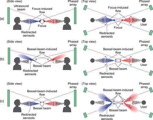
The second strategy entails upward flows that travel over each user’s head, passing in front of their mouths (). These airflows are expected to guide emitted aerosols to the upper side of the emitter’s head, suppressing the aerosol transportation. In addition, the upward airflows near users can also deflect aerosols reaching from the mouth of the facing person. Therefore, this type of airflow is expected to provide a two-stage redirection of aerosols: first, emitted aerosols are largely redirected over the emitter by an airflow path near the emitter, and the remainder is secondarily redirected over the facing person by another airflow path near him or her. The airflows hitting users of the PV systems were reported to be sometimes uncomfortable, and the users were likely to weaken airflow or change its direction (Chen, Raphael, and Sekhar Citation2012; Melikov and Knudsen Citation2007), undermining the system’s efficiency. The airflows we introduce here are free from this problem because they travel along a sufficiently localized straight upward flow path that bypasses the users’ faces. In the experiment, the airflows toward the user’s heads were generated with an acoustic Bessel beam because the direction control of resulting acoustic streaming was easier than that using ultrasonic foci.
The third strategy is depicted in , a horizontal version of the second strategy. In the experiment, this airflow field was generated with a group of two acoustic Bessel beams that pass through the left and right sides of the user.
3. Experimental methods
3.1. Outline of experiments
In this paper, two categories of experiments were conducted. One is the quantitative evaluation of the proposed aerosol transmission suppression methods by counting the number of emitted particles captured by a particle counter. The other is visualizing the ultrasound-driven flow fields using particle image velocimetry (PIV). Firstly, these experiments were performed under five different experimental conditions with different spatial distributions of the flow fields. Secondly, another experiment was additively performed to assess the performance of the proposed methods when adjusting the flow position corresponding to the emitter’s movement.
3.2. Experimental environments
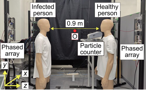
shows the fabricated prototype system used in the experiments. Two manikins representing two people facing each other were installed, with a distance between their mouths set to 0.9 m, slightly shorter than a general standard of physical distancing (1–2 m). This situation is equivalent of one where two people sit facing each other across a table. The left manikin representing an infected person had a smoke outlet facing the -axis, whose center position was
A particle counter TSI3330 (TSI Incorporated, USA) was set near the mouth of the right manikin representing a healthy person to capture the particles around it, with its suction nozzle located at
Eight phased array units were installed symmetrically behind each manikin, forming four ultrasound emission planes with their center position set to
Each emission plane was composed of two array units, and they formed apertures of 182.7 mm × 294.2 mm. The normal vectors of array planes are tilted against the
-axis by 26.57 degrees. As confirmed in the following experiments, the width of ultrasound beams is almost comparable to the array width. The manikins were located so that they did not occlude the array surfaces in all conditions. Acoustic streaming toward the right manikin was generated with the two array planes behind the left one and vice versa. Air-conditioning equipment in the experimental room was not operated during all experiments; the room ventilation system was activated only during the experiments with the particle counter to estimate the effect of ambient airflows caused by the ventilation.
Figure 2. The prototype system used in the experiment. The point O shows the origin point of experimental data. Bold yellow arrows show the direction of coordinate axes.
3.3. Experimental conditions
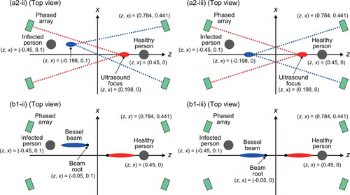
In this study, experiments were conducted under nine conditions: (a1), (a2-i), (a2-ii), (a2-iii), (b1-i), (b1-ii), (b1-iii), (b2), (c). Five conditions (a1), (a2-i), (b1-i), (b2), and (c) aimed at assessing the effectiveness of the proposed methods for suppressing aerosol transportation (). The other four conditions (a2-ii), (a2-iii), (b1-ii), and (b1-iii) aimed at assessing the validity of the proposed strategy when the left manikin is translated along the -axis (). The condition numberings stand for the combination of a flow type across (a)-(c) shown in , spatial variation of the beam formation in (a) and (b) indicated by Arabic numerals 1 or 2, and the last indicator i, ii, or iii designating the horizontal positioning of the left manikin and the flow. Note that we only changed the driving phases of each transducer when changing the experimental condition and generated flow fields.
Figure 3. Outline of five conditions (a1), (a2-i), (b1-i), (b2), and (c). All coordinates are indicated in meters.
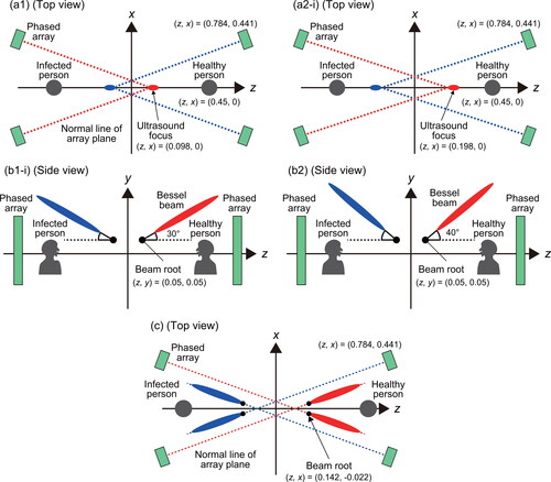
Figure 4. Outline of the other four conditions (a2-ii), (a2-iii), (b1-ii), and (b1-iii) to assess the validity of our method when the left manikin was moved. The lengths in the figures are in meters. Note that the Bessel beams were tilted upward and passed above the user’s head as conditions (b1-i) and (b2).
Two conditions (a1) and (a2-i) correspond to , where a pair of ultrasound focuses for realizing a pair of horizontal flows toward each user were created. In condition (a1), two focal positions were and in condition (a2-i), two focal positions were
For (a1), the foci were located on the points of intersection of the
-axis with normal vectors of array planes rooted on their centers. The distance between focal positions and users in (a2-i) is smaller than in (a1).
Two conditions (b1-i) and (b2) correspond to , where a pair of upward ultrasound Bessel beams were created for realizing a pair of upward flows passing by the user’s heads. The beam root positions were set to The beam direction was defined by the elevation angle between the
-axis and the central axis of wavefront cones in the
plane. This angle was set to 30 and 40 degrees in conditions (b1-i) and (b2), respectively. The vertex angle of the wavefront cone was adjusted to enhance the magnitude of acoustic intensity in front of the user and to produce the desired flows.
Condition (c) corresponds to , where four ultrasound Bessel beams were created for realizing airflows that passed through the sides of users to transport aerosols behind them. Each array plane produced a single Bessel beam perpendicular to the plane, whose root was located 1.036 m away from it. The four roots were set to The directions of Bessel beams were identical to the normal vector of each array plane, and the angle between those vectors and the z-axis was 26.57 degrees.
In practical situations, peoples’ bodies occasionally move. Because the cross-section of acoustic streaming is smaller than that of a fan or jet, the efficiency of our methods may deteriorate when the mouths of emitters deviate from the sweet spot of the generated acoustic streaming. Therefore, four additional conditions (a2-ii), (a2-iii), (b1-ii), and (b1-iii) were set for assessing the validity of our strategy when the left manikin was translated by 0.1 m along the -axis, where the position of the smoke outlet on the left manikin was
Firstly, under two conditions (a2-ii) and (b1-ii), acoustic streaming spatially adjusted to the movement of the user’s head was generated. In (a2-ii), the focus position near the left manikin was moved to make a focal point in front of the left manikin, and the two focal points were and
In (b1-ii), a pair of upward Bessel beams whose direction and vertex angle of wavefront cone were the same as (b1-i) was generated, but the position of the Bessel beam near the left manikin was moved to adjust to the left manikin’s movement. The position of the two beam roots were
and
Secondly, under two conditions (a2-iii) and (b1-iii), acoustic streaming with its position not adjusted to the movement of the manikin head was generated. The driving phases of each transducer under (a2-iii) and (b1-iii) were the same as those under (a2-i) and (b1-i), respectively.
3.4. PIV-based flow visualization procedures
We measured flow fields in or
planes based on the PIV technique. Tracer particles produced by a smoke machine (PS-2006, Dainichi Co., Ltd., Japan) was used and their movements were visualized by a laser sheet whose wavelength was 638 µm (KLD-V, Kato Koken Co. Ltd., Japan) and shot by a high-speed camera (k6 Kato Koken Co. Ltd., Japan), whose framerate was set to 250 fps. In all measurements of flow fields, the stand and the particle counter near the right manikin were removed. We kept the two manikins in the workspace when measuring the flow fields on the
plane, while the left manikin was removed so that the laser sheet could come in front of the right one in the flow field measurement on the
plane.
3.5. Generation of aerosols
We used Model 9306 six-jet atomizer (TSI Incorporated, USA) to produce the aerosols imitating exhaled air. The aerosols were ejected at a volume flow rate of 10.0 L/min in all experiments with the particle counter. This flow rate is almost equal to air released by breathing and talking (Gupta, Lin, and Chen Citation2010; Stettler et al. Citation2022). Glycerin solution was chosen as a source of aerosols because it is visible, nonvolatile, and utilized in previous studies for the same purpose (Pantelic et al. Citation2009; Li et al. Citation2022; Verma, Dhanak, and Frankenfield Citation2020). Prior to the experiment, it was confirmed that the particle size distribution of the generated aerosols was different from that of actual aerosols emitted by humans, which are mostly less than 1 µm (Archer et al. Citation2022; Gregson et al. Citation2021). At the same time, the generated aerosols contained a sufficient amount of aerosols whose sizes are almost equal to actual exhaled air. Thus, it is possible to assess how effectively our method can suppress the transportation of those particles. The maximum -component of the particle velocity near the outlet was 0.663 m/s in time-averaged value.
3.6. Measurement of the number of aerosol particles reaching the particle counter
In the experiments, the number of aerosols reaching near the right manikin was captured by the particle counter TSI3330. Particles captured by TSI3330 were classified into several groups by their diameters and the number of particles classified into each group was counted. After that, the total particle number, the number of the particles with less than 1.117 µm diameter (sub-micron range), and that with 1.117∼5.182 µm diameter (medium range) were calculated.
The data acquisition interval of TSI3330 was set to 15 s and it was run for 600 s continually to collect 40 data. Then, the influence of deadtimes (duration in which particle number was not counted successfully) was eliminated by multiplying by into the raw data, where
[s] is the deadtime recorded by the particle counter. Before emitting smoke from the outlet of the left manikin, the time-average value under the condition where no smoke was emitted was obtained. This value was subtracted from the raw data to obtain an estimate of particle numbers near the right manikin that was delivered from the left side.
Let be the number of particles captured by TSI3330 at the
-th temporal slot
and classified into a certain particle diameter group after correcting the influence of deadtime and background particles. The following calculation is performed individually for data with each size group. In the study, indicators of transported particle numbers without acoustic streaming (
) and with streaming (
) were defined by the following expressions:
(4)
(4)
(5)
(5)
where
and
is the value of
with the phased array inactivated and activated, respectively. In EquationEquation (4)
(4)
(4) ,
means average across appropriate periods when data collection was completed successfully. The ‘inappropriate’ period is when
becomes smaller than zero because of long deadtimes caused by instantaneous saturation of particle counter input. When calculating
the data corresponding to
were not used because the emitted aerosols did not reach the particle counter yet.
In each condition, seven experiment sets were conducted and collected seven groups of in each condition. A set consists of two trials, one with acoustic streaming and the other without. After that, a mean and standard deviation of
in each condition were calculated, excluding the maximum and minimum values among seven experimental sets, which were regarded as two outliers of temporally fluctuating measurement (therefore, data for the five experimental sets were used for calculation.). The temporal fluctuation here refers to the long-term one that cannot be canceled by summation of 600 s sampling data, which may result from fluctuation of ambient flow field due to room ventilation activated during the experiment. In the qualitative observations of smoke described below, such long-term fluctuations of smoke movement in absence of emitted ultrasound beams were actually confirmed.
3.7. Qualitative observations of redirected smoke
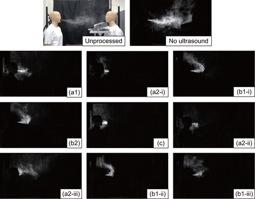
The movement of smoke emitted from the mouth of the left manikin under all nine conditions was shot by a video camera (FDR-AX60, SONY Corporation, Japan) with 60 fps. To visually enhance the smoke movement, four-stage image processing to raw color images was applied: conversion into black-and-white images, background subtraction, brightness adjustment, and time-averaging of ten captured frames (1/6 s in total time) for high-frequency noise reduction.
3.8. Estimation of the risk of infection using Wells-Riley Model
Estimation of a reduction in the risk of infection with our method was performed using the Wells-Riley model as in previous studies (Bale et al. Citation2022; Prentiss, Chu, and Berggren Citation2020), where infectious aerosols are assumed to fill the room uniformly. Although this assumption may not fully reflect our experiments handling a close contact situation, we used this model thanks to its simplicity.
In this study, a basic type of Wells-Riley model (“REHVA COVID-19 guidance document version 4.1” Citation2021) was used. The probability of infection can be written as:
(6)
(6)
where
is the normalized amount of inhaled viruses. The case
is equivalent to a situation where the probability of infection is
The value
is expressed by the product of the average normalized concentration of virions
[m−3], the volume of inhaled air with breathing
[m3/s], and the duration of people staying together in the room
[s].
Let and
be the probability of infection and the normalized number of inhaled viruses without our proposed system. Similarly, let
and
be those with our proposed system activated. Based on EquationEquation (6)
(6)
(6) ,
and
can be written as
and
respectively. We also define
which is the ratio of the inhaled viruses with the ultrasound system to that without the ultrasound system. By these equations, the relationship between
and
can be written as
(7)
(7)
The value can be written as
where subscripts “ON” and “OFF” correspond to whether or not ultrasound is emitted. For simplicity, we assumed that the volume of inhaled air is not affected by whether the proposed system is activated and staying time is the same, concluding that
and
These assumptions yield
It is difficult to give a specific value of virus concentration because its value depends on multiple factors such as varieties of virion and properties of aerosols. Therefore, we also assume that the virus concentration is only proportional to the number of particles in the air. Under this assumption, the ratio is equal to the ratio of time-average particles detected by the particle counter with acoustic streaming to that without acoustic streaming. Here, the value
can be written as
By substituting the experimentally obtained average of the ratio of total particle number
for
in EquationEquation (7)
(7)
(7) for each condition, the effectiveness for infection risk reduction for given values of
was estimated.
4. Results
4.1. Qualitative observations of redirected smoke
shows the smoke movement under all nine conditions, indicating that the produced acoustic streaming prevented a cluster of smoke from transporting to the right side. Notably, it was observed that a cluster of smoke was transported above the user’s head as intended in the cases with upward Bessel beams. In (a2-iii), smoke transportation was suppressed for most of the recording period, but occasionally ejected smoke reached the right side. Contrastingly, even in the case of (b1-iii), where the beam position was not adjusted, the smoke was successfully redirected above the user’s head, like condition (b1-i).
Figure 5. The movement of ejected smoke under the conditions (a1), (a2-i), (b1-i), (b2), (c), (a2-ii), (a2-iii), (b1-ii), and (b1-iii). The top left picture is unprocessed, and the other ten pictures were obtained via image processing against raw images.
4.2. Counting particles transported to the manikin on the right side
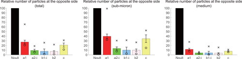
shows the values of for the first five conditions (a1), (a2-i), (b1-i), (b2), and (c). In all those conditions, the proposed system significantly suppressed aerosol transportation in close contact. In the cases of (a2-i), (b1-i), and (b2), the aerosols reaching the right manikin were suppressed largely by acoustic streaming. The experiments showed that the number of sub-micron range particles reaching the right side were reduced by 86.24%, 89.72%, and 89.95% in conditions (a2-i), (b1-i), (b2) on average, respectively. As mentioned earlier, the reduction of sub-micron range aerosols reaching facing person is the most important because they are emitted from breathing and talking. This result shows the effectiveness of the proposed system in suppressing transportation of exhaled aerosols by breathing and talking in close contact. Under conditions (a1) and (c), the overall performances were worse than (a2-i), (b1-i) and (b2). Reduction rates of sub-micron range aerosols under (a1) and (c) were 60.23% and 65.37%, respectively, which were more than 20 percentage points smaller than (a2-i), (b1-i), and (b2). Extremely poor outlier was observed under condition (a1). Under all conditions, larger effects on the suppression of medium-range aerosols than on the sub-micron range and the total number of aerosols transported to the right side were found. One possible reason for this is that the evaporation of water in the particles, resulting in a decreased particle diameter that was expedited by acoustic streaming, might contribute to the reduction of the medium-range particles captured by the particle counter. The particle concentrations under no ultrasound emission showed relative fluctuations of 28.56% (total particle number), 25.21% (sub-micron range), and 33.59% (medium range) as standard deviations divided by the average particle numbers in all trials under all the first five conditions.
Figure 6. Average values of captured particle numbers for the five experimental sets (excluding the maximum and minimum trial values from calculation) under (a1), (a2-i), (b1-i), (b2), and (c). “Noult” in the graph means the case under the phased array was inactivated. The error bars show the standard deviations and the symbols × and ○ show the maximum and minimum trial values, respectively.
4.3. Visualization and measurement of flow fields
shows measured acoustic streaming fields (time-averaged across five consecutive images captured during 0.02 s in total time) and corresponding acoustic intensity fields calculated via numerical simulations. In the simulations, each phased array transducer was modeled as a point source and the generated acoustic fields were calculated as performed in the previous works (Hasegawa, Yuki, and Shinoda Citation2019; Kitano and Hasegawa Citation2023). Manikin, stand, and particle counter were not modeled in the simulations. Note that the acoustic intensity fields are physically not identical to the resulting flow fields, but they correspond to the acceleration field of the flow field. We calculated them to discuss the forming mechanism of the flow field out of the acoustic acceleration.
Figure 7. components (left column) and the vector plots (middle column) of measured flow fields and simulated acoustic intensity field corresponding to the flow acceleration field (right column) under the five conditions (a1), (a2-i), (b1-i), (b2), and (c). Black dots show the position of the dual acoustic focal points, and black lines show the central axis of each Bessel beam. In the cases of (a1), (a2-i), and (c), flow fields on the
plane were measured. In the cases of (b1-i) and (b2), flow fields on the
plane were measured. In the cases of (a1) and (a2-i), the ‘intentional flows’ referred to the main text are surrounded by dotted lines. The ‘unintentional flows’ in those cases refer to the flows outside the dotted lines.
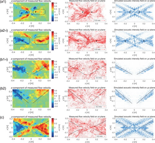
For (a1) and (a2-i), airflows toward individual users were observed as expected. At the same time, unintentional leftward and rightward flows toward the workspace center (the flow fields outside the dotted region in and (a2-i)) occurred as a side effect. shows the maximum absolute value of the -component of the flow fields on the
plane in the region of intentional and unintentional flows at the time shown in , which shows that the amplitudes of unintentional flows were larger than those of intentional flows in (a1). In contrast, the intentional flows were stronger than unintentional ones, extending near the manikins in (a2-i). These differences are ascribed to the differences in acceleration fields of the air, i.e., acoustic intensity fields depicted in . The acceleration field toward the emitters in (a2-i) is stronger, more spread, and closer to the emitters, in comparison with those in (a1).
Table 1. The maximum absolute value of the -component of the flow fields on the measurement plane at the time, as shown in .
Under conditions (b1-i) and (b2), a pair of upward flows passing over two manikins were observed. The elevation angle of generated flows from the ground was smaller than that of Bessel beams. The right column of shows that the directions of acoustic intensity vectors on the beam paths were also slightly different from the designed elevation angle. It is considered that this is because the Bessel beams were produced by two separate array planes, not by a single large array plane as in preceding studies.
Under condition (c), flows toward each user from the workspace center and those toward the center coexisted. From , the magnitudes of these two airflows were almost equal. Here, the generated flows were different from the desired ones that passed through the left and right sides of users. Therefore, this type of flow may be effective in preventing aerosol transportation but not in preventing the aerosols around the users from directly hitting their faces. The maximum absolute value of the -component of the flow field on the
plane in (c) was 0.447 m/s, as shown in . This value is smaller than the values in the other conditions, presumably because the number of flows that was intended to produce was four under this condition while it was two under other conditions, lowering the beam intensity.
4.4. Acoustic field designing according to positional change of the infectious person
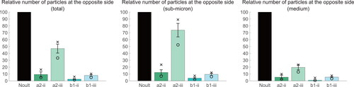
shows the values of for the four conditions (a2-ii), (a2-iii), (b1-ii), and (b1-iii), calculated in the same way as in Section 4.2. The reduction rates of captured sub-micron range aerosols were 87.77% and 26.26% under conditions (a2-ii) and (a2-iii), respectively. Those results indicate that changing the position of acoustic foci can keep the performance of particle transportation suppression against the movement of the emitter, and the performance significantly worsened when the focal position was unadjusted. The reduction rates of transported sub-micron range aerosols were 96.11% and 90.55% under the conditions (b1-ii) and (b1-iii), respectively. The reduction rate was highest in case (b1-ii) among four conditions where the manikin was moved. The reduction rate of sub-micron range aerosols under (a2-i) and (a2-ii) were comparable, and that under (b1-ii) was even better than under (b1-i) by 6.39 percentage points. Those results suggest that properly shifted ultrasound beam can maintain the system performance against the users’ movement. It is also demonstrated that using the Bessel beam, our proposed system can suppress exposure to aerosols even when the beam position is fixed, regardless of the user’s slight position shift. The particle concentrations under no ultrasound emission showed relative fluctuations of 19.69% (total particle number), 15.43% (sub-micron range), and 26.65% (medium range) as standard deviations divided by the average particle numbers in all trials under all conditions where the left manikin was moved.
Figure 8. The average, standard deviation, maximum value, and minimum value of experimental sets under (a2-ii), (a2-iii), (b1-ii), and (b1-iii). The graphs were created in line with the same procedures as in .
4.5. Estimation of the risk of infection using Wells-Riley Model
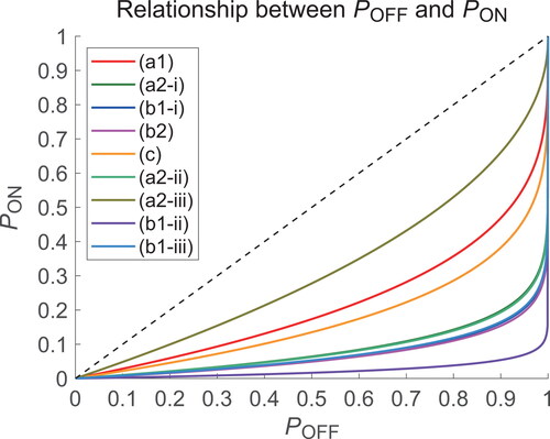
shows the values of against that of
for the nine experimental conditions, showing that
gets smaller as
is smaller for fixed values of
We now consider the case of
for example, which is reasonable for a situation where an infectious person and a healthy person stay together in a poorly ventilated space for a long time (Sun and Zhai Citation2020). Using
calculated with the result of each condition,
is 0.0934, 0.0335, 0.0270, 0.0256, 0.0719, 0.0328, 0.1542, 0.0086, and 0.0276 under (a1), (a2-i), (b1-i), (b2), (c), (a2-ii), (a2-iii), (b1-ii), and (b1-iii), respectively. The corresponding reduction rates of the probability of infection
are 68.88%, 88.83%, 91.00%, 91.48%, 76.02%, 89.08%, 48.60%, 97.15%, and 90.80%, respectively. This result shows that the proposed system can considerably reduce the risk of infection by 97% in the case of upward Bessel beams.
Figure 9. The relationship between and
as calculated by EquationEquation (7)
(7)
(7) , with the average value of
in each condition.
5. Discussion
5.1. Suppression efficiency of particle transportation and acoustic streaming field design
The reduction rate of aerosols reaching the particle counter under condition (a1) was the lowest among the five conditions in . It is considered that the unwanted flows stronger than the intended ones unintentionally expedite particles reaching the particle counter. Under (a2-i), a pair of intentional horizontal airflows extending near users from the workspace center were observed, which suppressed aerosol transportation immediately after being emitted from the outlet. The unintentional flows under (a2-i) were weaker than those under (a1), presumably resulting in fewer aerosols being transported to the right side. Under the conditions (b1-i) and (b2) using the Bessel beam propagating above users’ heads, the numbers of captured sub-micron aerosols were reduced by approximately 90%. Under these conditions, unintended airflows like the ones stated above were not generated. In addition, even if aerosols were entering the opposite side, the paired upward airflows are expected to deflect the aerosols around the users toward above their heads. This mechanism is the second phase of the ‘two-stage’ aerosol redirection previously explained. As already stated, low performance under condition (c) can be ascribed to a low velocity of the acoustic streaming field.
When the manikin’s head was moved, the performance under condition (a2-iii), where the position of acoustic streaming was unchanged from that of (a2-i), was the lowest among the four conditions in . After moving the left manikin, its smoke outlet was positioned closer to the unintentional flows observed under (a2-i), and more aerosols reached the particle counter than under the other conditions. On the other hand, the condition (b1-iii) with an upward Bessel beam slightly deviating from the outlet showed good performance. indicates that emitted smoke was guided along this horizontally misaligned flow and transported upwards. Thus, flows generated by upward Bessel beams more robustly redirected emitted aerosols against the misalignment between the ejector and the flows, which is advantageous in practical use. Like conditions (b1-i) and (b2), the airflow on the right side is also expected to deflect aerosols near its mouth. In the experiments, whether variation in vertical positions of the flows and users’ mouth was not evaluated. Flows produced by ultrasound acoustic focuses were distributed in the horizontal plane, not the vertical plane. This may result in low performance against vertical change in user’s mouth. On the other hand, flows produced by upward ultrasound Bessel beam were distributed in the vertical plane, and those flows was expected to redirect emitted aerosols robustly against vertical misalignment between the ejector and the flows as cases in horizontal misalignment.
5.2. Comparison of our results with the previous study of personalized ventilation
The best reduction rate of sub-micron range aerosols when two people face each other was approximately 90% in this study. In contrast, in the study by Katramiz et al. it was more than 90% when using the PV system at maximum output (Katramiz et al. Citation2021). Although several experimental conditions of those two works are different, it is difficult to claim that the performance of our proposed system is unconditionally superior to past PV systems.
In the previous studies of PV, it was reported that a high reduction in concentration was achieved with a high flow rate (Katramiz et al. Citation2021; Li, Niu, and Gao Citation2013; Xu et al. Citation2020). However, large flow velocity near the user may be uncomfortable for users and lead them to weaken the flow rate of the PV machine, which may decrease the effectiveness of the PV system (Chen, Raphael, and Sekhar Citation2012; Melikov and Knudsen Citation2007). In the previous study by Xu et al. and Katramiz et al. the flow velocity near the user was 2.19 m/s and 1.12 m/s, respectively, at the PV machine’s maximum output (Xu et al. Citation2020; Katramiz et al. Citation2021). As shown in , the flow velocity near the user was much weaker than in those studies under the conditions using the upward Bessel beams. It was an outstanding feature that the proposed system could handle mitigating the flow velocity near the user by not hitting the acoustic streaming directly on the user’s face and preventing exhaled aerosols from being transported to the other side by redirecting the paths of aerosols.
In the PV system, the direction of jet flow was fixed. In contrast, in our proposed system, the direction of acoustic streaming can be easily changed by only changing the driving phases of each transducer of phased arrays, not the direction of array surfaces. In addition, the performance of the proposed system was stable when the user’s position was slightly changed, as shown in Section 4.4. These features are superior to the PV system.
6. Limitations
We focused on the situation where two people face each other and other possible cases where the other person stays behind the users of the proposed system, for instance, were excluded. In those cases, the Bessel-beam-based strategy might be inappropriate because of the aerosols transported to that person behind. It was reported that when two people were sitting in line, airflow directly delivered to the front person expedited the transportation of aerosols to the other person (Katramiz et al. Citation2021). Also, when three or more people are in close contact, our proposed system may not always be effective for infectious control. This study aims to prevent only the short-range exposure to the infectious aerosols. The exhaled aerosols are only redirected away from the users, but are not removed from a room with the proposed method. Those remaining aerosols may be still hazardous to people, so room ventilation or aerosol removal with air filters are preferable to be used simultaneously.
In this study, it was demonstrated that the flows adjusted so that they pass through just in front of the emitter’s mouths can achieve better performance. Since this was validated for static cases only, the effect of dynamic control of beam position should be assessed in suppressing the transportation of aerosols ejected from the mouths of continuously moving users. Furthermore, it may be important to investigate the effect of the user’s head orientation on the performance of the suppression efficiency, as in a previous study (Xu et al. Citation2022).
In this study, the effect of thermal plume around the user’s body and inhalation within a period of breathing were not considered. In the previous study of personalized ventilation, these effects were considered by conducting experiments with breathing thermal manikin or elaborate simulations (Cermak et al. Citation2006; Katramiz et al. Citation2021; Li, Niu, and Gao Citation2013; Pantelic et al. Citation2009; Xu et al. Citation2020). It is likely that the thermal plume may contribute to pushing the aerosols near the users’ faces upward above their heads. Interaction between acoustic streaming and these factors may produce a complex flow field near the user’s mouth, and its effect on suppression efficiency should also be assessed.
In the experiments, smoke was constantly ejected at a flowrate of 10 L/min from the manikin, but actual human breathing is more intermittent, and its instantaneous flowrate can be more than that. The performance of the proposed system in those situations cannot be directly evaluated in the experiment. Nevertheless, because the generated acoustic streaming kept its velocity along several tens of millimeters, it is expected that those flows can effectively decelerate and redirect aerosols emitted via impulsive respiratory actions.
The safety of exposure to intense midair ultrasound has been discussed (Rakkolainen et al. Citation2021). It is reported that when exposed to 40 kHz ultrasound, which is utilized in this study, its pressure is required to be less than 140 dB SPL on instantaneous maximum and less than 110 dB SPL for continuous exposure (Smagowska and Pawlaczyk-Łuszczyńska Citation2013). Sound pressure near the manikin’s ear was measured with a standard microphone (type 4138-A-015, Bruel and Kjaer, Denmark), and it was verified that the time-constant pressure value was 120–130 dB SPL under the five conditions in . Although the pressure was less than 140 dB SPL, a smaller sound pressure is preferable especially for long-term system operation or with systems extended for three or more people employing a greater number of array units. Arranging phased arrays more apart from users and constructing larger array planes for more localized acoustic power concentration may circumvent exposing users directly to intense ultrasound.
The phased array system used in the experiments is not readily implemented or affordable. At the same time, new techniques to generate spatially fixed ultrasound beams with a simpler and much less expensive configurations are being developed (Kitano and Hasegawa Citation2023), which can potentially be applied to the scenario where upward Bessel beams are used.
7. Conclusion and future work
In this study, we proposed a strategy for suppressing the transportation of infectious aerosols in exhaled air to other people using acoustic streaming produced by ultrasound phased arrays. We experimentally verified the strategy’s effectiveness using a fabricated prototype system for two people facing each other over a short distance. Especially, acoustic streaming produced by a pair of upward Bessel beams passing above users’ heads can reduce the transported aerosols whose diameter is equal to those emitted during breathing and talking by 89.95%. Furthermore, the performance of the prototype system was maintained when the aerosol ejector was shifted by appropriately controlling the phased arrays.
Plans for this study include:
Construction of a large-scale system that is effective for more than three people sharing a workspace.
Realizing the dynamic redirection of aerosols emitted from users that move freely.
Controlling macroscopic airflow paths in the room, not between two users, for infection control with the support of acoustic streaming.
Since the reconfiguration of the airflow positions and directions are promptly done in an electronic manner with our method, those plans are ultimately expected to be implemented in a real-time fashion. As addressed in this study, remote and contactless midair air acceleration is advantageous for infection control due to its intrinsically contactless nature. There is great potential for further development in enlarging the scope of practical application scenarios to include a diagnostic room with a patient and a physician, a café filled with many people, or sports sites in which many players continuously run around the court.
Supplemental Material
Download MP4 Video (24.7 MB)Acknowledgments
The authors thank Prof. Takaaki Nara and Dr. Hiroki Miyazako for their helpful comments and advice throughout this study. The authors also thank Dr. Hitoshi Oshitani for providing insightful comments regarding this study.
Disclosure statement
The contact author has declared that none of the authors have competing interests.
Additional information
Funding
References
- Archer, J., L. P. McCarthy, H. E. Symons, N. A. Watson, C. M. Orton, W. J. Browne, J. Harrison, B. Moseley, K. E. J. Philip, J. D. Calder, et al. 2022. Comparing aerosol number and mass exhalation rates from children and adults during breathing, speaking, and singing. Interface Focus. 12 (2):20210078. doi:10.1098/rsfs.2021.0078.
- Bale, R., A. Iida, M. Yamakawa, C. Li, and M. Tsubokura. 2022. Quantifying the COVID19 infection risk due to droplet/aerosol inhalation. Sci. Rep. 12 (1):11186. doi:10.1038/s41598-022-14862-y.
- Bartels, J., C. F. Estill, I. Chen, and D. Neu. 2022. Laboratory study of physical barrier efficiency for worker protection against SARS-CoV-2 while standing or sitting. Aerosol Sci. Technol. 56 (3):295–303. doi:10.1080/02786826.2021.2020210.
- Cermak, R., A. K. Melikov, L. Forejt, and O. Kovar. 2006. Performance of Personalized Ventilation in Conjunction with Mixing and Displacement Ventilation. HVAC&R Res. 12 (2):295–311. doi:10.1080/10789669.2006.10391180.
- Chen, W., N. Zhang, J. Wei, H. Yen, and Y. Li. 2020. Short-range airborne route dominates exposure of respiratory infection during close contact. Build. Environ. 176:106859. doi:10.1016/j.buildenv.2020.106859.
- Chen, Y., B. Raphael, and S. C. Sekhar. 2012. Individual control of a personalized ventilation system integrated with an ambient mixing ventilation system. HVAC&R Res. 18 (6):1136–52. doi:10.1080/10789669.2012.710059.
- Cowger, T. L,., J. Murray, M. T. Clarke, B. O. Bassett, S. M. Ojikutu, N. Sánchez, K. T. Linos, and Hall, E. J. 2022. Lifting Universal Masking in Schools – Covid-19 Incidence among Students and Staff. N Engl. J. Med. 387 (21):1935–46. doi:10.1056/NEJMoa2211029.
- Eckart, C. 1948. Vortices and Streams Caused by Sound Waves. Phys. Rev. 73 (1):68–76. doi:10.1103/PhysRev.73.68.
- Eykelbosh, A. 2021. A rapid review of the use of physical barriers in non-clinical settings and COVID-19 transmission. National Collaborating Centre for Environmental Health (NCCEH), Vancouver, BC. Accessed December 25, 2021.
- Federation of European Heating Ventilation and Air Conditioning Associations. 2021. REHVA COVID19 guidance version 4.1. Federation of European Heating Ventilation and Air Conditioning Associations. Accessed January 21, 2023. https://www.rehva.eu/fileadmin/user_upload/REHVA_COVID-19_guidance_document_V4.1_15042021.pdf
- Gregson, F. K. A., N. A. Watson, C. M. Orton, A. E. Haddrell, L. P. McCarthy, T. J. R. Finnie, N. Gent, G. C. Donaldson, P. L. Shah, J. D. Calder, et al. 2021. Comparing aerosol concentrations and particle size distributions generated by singing, speaking, and breathing. Aerosol Sci. Technol. 55 (6):681–91. doi:10.1080/02786826.2021.1883544.
- Gupta, J. K., C. Lin, and Q. Chen. 2010. Characterizing exhaled airflow from breathing and talking. Indoor Air. 20 (1):31–9. doi:10.1111/j.1600-0668.2009.00623.x.
- Hasegawa, K., L. Qiu, A. Noda, S. Inoue, and H. Shinoda. 2017. Electronically steerable ultrasound-driven long narrow air stream. Appl. Phy. Lett. 111 (6):064104. doi:10.1063/1.4985159.
- Hasegawa, K., L. Qiu, and H. Shinoda. 2018. Midair Ultrasound Fragrance Rendering. IEEE Trans. Vis. Comput. Graph. 24 (4):1477–85. doi:10.1109/TVCG.2018.2794118.
- Hasegawa, K., H. Yuki, and H. Shinoda. 2019. Curved acceleration path of ultrasound-driven airflow. J. Appl. Phy. 125 (5):054902. doi:10.1063/1.5052423.
- Kamakura, T., K. Yasuda, and Y. Kumamoto. 1999. Unified description of second-order phenomena in sound waves. Electron. Comm. Jpn. Pt. III. 82 (2):76–82. doi:10.1002/(SICI)1520-6440(199902)82:2<76::AID-ECJC9>3.0.CO;2-Q.
- Katramiz, E., N. Ghaddar, K. Ghali, D. Al-Assaad, and S. Ghani. 2021. Effect of individually controlled personalized ventilation on cross-contamination due to respiratory activities. Build. Environ. 194:107719. doi:10.1016/j.buildenv.2021.107719.
- Kitano, M., and K. Hasegawa. 2023. Airborne ultrasound focusing aperture with binary amplitude mask over planar ultrasound emissions. J. Appl. Phy. 133 (14):144901. doi:10.1063/5.0140604.
- Lessler, J., M. K. Grabowski, K. H. Grantz, E. Badillo-Goicoechea, C. J. E. Metcalf, C. Lupton-Smith, A. S. Azman, and E. A. Stuart. 2021. Household COVID-19 risk and in-person schooling. Science 372 (6546):1092–7. doi:10.1126/science.abh2939.
- Li, W., A. Chong, B. Lasternas, T. G. Peck, and K. W. Tham. 2022. Quantifying the effectiveness of desk dividers in reducing droplet and airborne virus transmission. Indoor Air. 32 (1):e12950. doi:10.1111/ina.12950.
- Li, X,., N. Niu, and Gao, J. 2013. Co-occupant’s exposure to exhaled pollutants with two types of personalized ventilation strategies under mixing and displacement ventilation systems. Indoor Air. 23 (2):162–71. doi:10.1111/ina.12005.
- Lighthill, J. 1978. Acoustic streaming. J. Sound Vib. 61 (3):391–418. doi:10.1016/0022-460X(78)90388-7.
- Lindsley, W. G., F. M. Blachere, D. H. Beezhold, R. E. Thewlis, B. Noorbakhsh, S. Othumpangat, W. T. Goldsmith, C. M. McMillen, M. E. Andrew, C. N. Burrell, et al. 2016. Viable influenza A virus in airborne particles expelled during coughs versus exhalations. Influenza Other Respir. Viruses. 10 (5):404–13. doi:10.1111/irv.12390.
- Liu, L., Y. Li, P. V. Nielsen, J. Wei, and R. L. Jensen. 2017. Short-range airborne transmission of expiratory droplets between two people. Indoor Air. 27 (2):452–62. doi:10.1111/ina.12314.
- Marr, L. C., and J. W. Tang. 2021. A Paradigm Shift to Align Transmission Routes With Mechanisms. Clin. Infect. Dis. 73 (10):1747–9. doi:10.1093/cid/ciab722.
- Melikov, A. K. 2004. Personalized Ventilation. Indoor Air. 14 (s7):157–67. doi:10.1111/j.1600-0668.2004.00284.x.
- Melikov, A. K., and G. L. Knudsen. 2007. Human Response to an Individually Controlled Microenvironment. HVAC&R Research 13 (4):645–60. doi:10.1080/10789669.2007.10390977.
- Milton, D. K. 2020. A Rosetta Stone for Understanding Infectious Drops and Aerosols. J. Pediatric Infect. Dis. Soc. 9 (4):413–5. doi:10.1093/jpids/piaa079.
- Morawska, L., and J. Cao. 2020. Airborne transmission of SARS-CoV-2: The world should face the reality. Environ. Int. 139:105730. doi:10.1016/j.envint.2020.105730.
- Morens, D. M., P. Daszak, H. Markel, and J. K. Taubenberger. 2020. Pandemic COVID-19 Joins History’s Pandemic Legion. mBio 11 (3):e00812-20. doi:10.1128/mBio.00812-20.
- Nyborg, W. L. 1953. Acoustic Streaming due to Attenuated Plane Waves. Journal of the Acoustical Society of America 25 (1):68–75. doi:10.1121/1.1907010.
- Olmedo, I., P. V. Nielsen, M. Ruiz de Adana, R. L. Jensen, and P. Grzelecki. 2012. Distribution of exhaled contaminants and personal exposure in a room using three different air distribution strategies. Indoor Air. 22 (1):64–76. doi:10.1111/j.1600-0668.2011.00736.x.
- Pantelic, J., G. N. Sze-To, K. W. Tham, C. Y. H. Chao, and Y. C. M. Khoo. 2009. Personalized ventilation as a control measure for airborne transmissible disease spread. J. R Soc. Interface 6 (Suppl 6):S715–S726. doi:10.1098/rsif.2009.0311.focus.
- Prentiss, M., A. Chu, and K. K. Berggren. 2020. Superspreading events without superspreaders: Using high attack rate events to estimate N0 for airborne transmission of COVID-19. medRxiv. doi:10.1101/2020.10.21.20216895.
- Rakkolainen, I., E. Freeman, A. Sand, R. Raisamo, and S. Brewster. 2021. A survey of mid-air ultrasound haptics and its applications. IEEE Trans. Haptics. 14 (1):2–19. doi:10.1109/TOH.2020.3018754.
- Smagowska, B., and M. Pawlaczyk-Łuszczyńska. 2013. Effects of ultrasonic noise on the human body – A bibliographic review. Int. J. Occup. Saf. Ergon. 19 (2):195–202. doi:10.1080/10803548.2013.11076978.
- Stettler, M. E. J., R. T. Nishida, P. M. de Oliveira, L. C. C. Mesquita, T. J. Johnson, E. R. Galea, A. Grandison, J. Ewer, D. Carruthers, D. Sykes, et al. 2022. Source terms for benchmarking models of SARS-CoV-2 transmission via aerosols and droplets. R Soc. Open Sci. 9 (5):212022. doi:10.1098/rsos.212022.
- Sun, C., and Z. Zhai. 2020. The efficacy of social distance and ventilation effectiveness in preventing COVID-19 transmission. Sustain. Cities Soc. 62:102390. doi:10.1016/j.scs.2020.102390.
- Suzuki, S., S. Inoue, M. Fujiwara, Y. Makino, and H. Shinoda. 2021. AUTD3: Scalable airborne ultrasound tactile display. IEEE Trans. Haptics. 14 (4):740–9. doi:10.1109/TOH.2021.3069976.
- Verma, S., M. Dhanak, and J. Frankenfield. 2020. Visualizing the effectiveness of face masks in obstructing respiratory jets. Phys. Fluids (1994)32 (6):061708. doi:10.1063/5.0016018.
- Wei, J., and Y. Li. 2016. Airborne spread of infectious agents in the indoor environment. Am. J. Infect. Control. 44 (9 Suppl):S102–S108. doi:10.1016/j.ajic.2016.06.003.
- Wiens, K. E., C. P. Smith, E. Badillo-Goicoechea, K. H. Grantz, M. K. Grabowski, A. S. Azman, E. A. Stuart, and J. Lessler. 2022. In-person schooling and associated COVID-19 risk in the United States over spring semester 2021. Sci. Adv. 8 (16):eabm9128. doi:10.1126/sciadv.abm9128.
- Xu, C., and L. Liu. 2018. Personalized ventilation: One possible solution for airborne infection control in highly occupied space. Indoor Built Environ. 27 (7):873–6. doi:10.1177/1420326X18777383.
- Xu, C,., L. Wei, L. Liu, W. Su, Y. Liu, P. V. Wang, and Nielsen, X. 2020. Effects of personalized ventilation interventions on airborne infection risk and transmission between occupants. Build. Environ. 180:107008. doi:10.1016/j.buildenv.2020.107008.
- Xu, J., C. Wang, S. C. Fu, and C. Y. H. Chao. 2022. The effect of head orientation and personalized ventilation on bioaerosol deposition from a cough. Indoor Air. 32 (1):e12973. doi:10.1111/ina.12973.