Abstract
The purpose of this study was to compare the dosimetric accuracy of IMRT plans for targets in lung with the accuracy of standard uniform-intensity conformal radiotherapy for different dose calculation algorithms. Tests were performed utilizing a special phantom manufactured from cork and polystyrene in order to quantify the uncertainty of two commercial TPS for IMRT in the lung. Ionization and film measurements were performed at various measuring points/planes. Additionally, single-beam and uniform-intensity multiple-beam tests were performed, in order to investigate deviations due to other characteristics of IMRT. Helax-TMS V6.1(A) was tested for 6, 10 and 25 MV and BrainSCAN 5.2 for 6 MV photon beams, respectively. Pencil beam (PB) with simple inhomogeneity correction and ‘collapsed cone’ (CC) algorithms were applied for dose calculations. However, the latter was not incorporated during optimization hence only post-optimization recalculation was tested. Two-dimensional dose distributions were evaluated applying the γ index concept. Conformal plans showed the same accuracy as IMRT plans. Ionization chamber measurements detected deviations of up to 5% when a PB algorithm was used for IMRT dose calculations. Significant improvement (deviations ∼2%) was observed when IMRT plans were recalculated with the CC algorithm, especially for the highest nominal energy. All γ evaluations confirmed substantial improvement with the CC algorithm in 2D. While PB dose distributions showed most discrepancies in lower (<50%) and high (>90%) dose regions, the CC dose distributions deviated mainly in the high dose gradient (20–80%) region. The advantages of IMRT (conformity, intra-target dose control) should be counterbalanced with possible calculation inaccuracies for targets in the lung. Until no superior dose calculation algorithms are involved in the iterative optimization process it should be used with great care. When only PB algorithm with simple inhomogeneity correction is used, lower energy photon beams should be utilized.
Intensity modulated radiotherapy (IMRT) is accepted as a state-of-the-art treatment technique for advanced photon beam therapy for head-and-neck and prostate cancer patients. The spectrum of typical IMRT indications is under permanent investigation and lung targets have always been a focus for IMRT Citation[1–3]. However, radiation therapy in the presence of inhomogeneous tissue (lung, bone) is associated with potential uncertainties in dose calculation, which fundamentally depend on the basic beam data used in the treatment planning system (TPS) and on the algorithms and/or corrections applied to account for density variations. Today, pencil beam (PB) models that are basically a compromise between accuracy and calculation speed are most widely used in inverse planning (IP) modules of TPSs.
Inherent limitation of a PB model, especially in lung, has been the subject of numerous papers, e.g. Knöös et al. Citation[4] and Engelsman et al. Citation[5]. Today, it is a well known fact that particularly for the highest photon energies clinically unacceptable underdosage can be introduced when using field sizes for conformal treatments based on a ‘beam's-eye-view’ technique and the PB model. Only recently were the first studies published dealing with impacts of inhomogeneities on IMRT. Laub et al. Citation[6] compared dosimetric measurements in IMRT beams, based on compensators, with films and thermoluminescent dosimeters (TLD) with Monte Carlo and pencil beam calculations in a thoracic phantom. No significant overestimation by the PB algorithm was found of doses inside the target or in lung. The authors stated that the expected PB dose calculation errors were suppressed, because the dose to the low-density region was reduced by using a non-coplanar beam arrangement and intensity modulation, which resulted in improved dose conformity. These findings are in contrast to the findings of Scholz et al. Citation[7] who compared IMRT plans based on a PB model and a superposition algorithm for dose calculation during optimization. They concluded that in target regions with intricate tissue inhomogeneities, either superposition or Monte Carlo techniques have to be used during optimization and for the final dose calculation of IMRT plans.
An overview of current knowledge and recommendations related to the problem can be found in AAPM Report No. 85 Citation[8]. The principal limitations of the PB model are an inadequate modeling of lateral electron transport and/or modeling of situations where electron equilibrium is not established, such as small segments used for IMRT delivery. These limitations can lead to qualitative as well as quantitative deviations when applying IMRT in lung region. To the knowledge of the authors no quantitative 2D data is available which deals specifically with IMRT.
The motivation for the present study was based on a treatment planning study published recently by our group Citation[9], in which substantial differences between dose distributions calculated by the PB and the CC algorithms were observed. The purpose of this study was to compare the dosimetric accuracy of IMRT with the accuracy of uniform-intensity conformal plans for targets in the lung achievable with PB and collapsed cone (CC) algorithms. By measuring 2D dose distributions and applying the γ criteria this can be done in a straightforward way.
Material and methods
Phantom design
A special phantom, simulating a tumor-in-lung treatment condition, was manufactured from cork and solid water. The phantom is schematically illustrated in . The total cork layer thickness was 12 or 14 cm, depending on experiment. A polystyrene cylinder (5 cm diameter, 5 cm height) was located in the center of the phantom. For treatment planning this cylinder was defined as clinical target volume (CTV) and a 5 mm isotropic margin was used to construct the PTV.
Figure 1. Lung phantom made of cork and solid water: Axial (left) and sagittal (right) cross-sections indicating location of a cylindrical tumor model and ionization chamber channels. Films were placed horizontally at the isocentric plane and 40 mm above and below it.
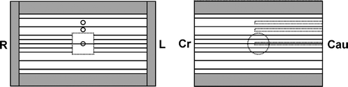
Solid water plates were used to mimic thoracic walls around the cork material. The phantom was designed in such a way that a small ionization chamber could be inserted into the tumor model and in two positions on the phantom axis in the cork slabs just above the tumor model (30 and 50 mm). Those chamber channels that were not used for measurements were filled with cork material. In this study only the isocentric measuring channel was used. A second identical tumor model was made of two half-cylinders in order to position films in its center.
CT images of the whole phantom were acquired with 4 mm slice thickness. The phantom orientation was chosen such that the rotation axis of the cylindrical tumor model was perpendicular to cranial-caudal axis.
Treatment planning systems
Two commercial TPSs were subjected to the study: Helax-TMS Version 6.1/6.1A, (Nucletron BV, Veenendaal, The Netherlands) and BrainSCAN Version 5.2 (Brainlab AG, Germany). Helax-TMS was commissioned for 6, 10 and 25 MV high energy photon beams provided by an ELEKTA Precise linear accelerator (Elekta Oncology Systems, Crawley, UK) whereas BrainSCAN was limited to 6 MV beams from the same linac. While Helax-TMS was used in conjunction with a standard MLC (1 cm width at isocenter), the BrainSCAN system was used in combination with an external micro-MLC (m3, Brainlab) with variable leaf width (3–5.5 mm at isocenter) and therefore mimics the Novalis system (Brainlab AG, Germany). Both TPSs apply PB models and equivalent path length (EPL) inhomogeneity correction. Helax-TMS allows for selection of a superior CC algorithm Citation[10] for final dose calculation.
On the other hand, both IP modules apply PB models and EPL inhomogeneity corrections during optimization. The two TPSs differ in fluence resolution which is, in one dimension, defined by leaf width. Furthermore, they differ in the optimization algorithm for IP and in leaf sequencing, i.e. the quadratic difference between desired and actual dose is used in Helax-TMS while the Dynamically Penalized Likelihood is applied in BrainSCAN Citation[11]. Leaf sequencing is parameterized by mean (BrainSCAN) or maximum (Helax-TMS) segment numbers, and in the latter TPS also by a ‘minimum segment area’. Two IMRT plans with similar dose distributions can differ substantially in segment number, segment size and shape according to different optimization and leaf sequencing algorithms. That is why leaf sequencing can affect the dosimetric accuracy.
Ionization measurements
All ionization measurements were performed utilizing a small-volume ionization chamber (PTW type 31002, 0.125 cm3), which was cross-calibrated in a 60Co beam against a Farmer type chamber (PTW type 31006, 0.6 cm3). The IAEA TRS-398 protocol Citation[12] was used for determination of the absorbed dose.
The ionization measuring point was inside the polystyrene tumor model, so the requested quantity was the absorbed dose in the material of the model and no additional correction was necessary.
Experimental setup
To enable the comparison of the dosimetric accuracy of IMRT plans to the accepted standards of conformal radiotherapy, measurements with single and conformal beams were carried out.
Single-beam arrangements
For single beam tests the phantom was irradiated with the AP square field (gantry angle 0°) of 6.9×6.9 cm2 size. The dose prescription was 2 Gy to the isocenter, which was located in the center of the tumor model. Ionization measurements were performed in the isocenter only. Mean doses of small volumes, which corresponded to the sensitive volume of the ionization chamber, were calculated with the TPS (DTPS). Relative dose distributions were measured with films stacked between cork slabs perpendicular to the beam axis. In total three films, one at the isocenter plane, one 40 mm above and one 40 mm below the isocenter were positioned in the phantom. Two-dimensional dose distributions were evaluated quantitatively by applying the γ index concept Citation[13].
Single-beam experiments were performed for 6, 10 and 25 MV beams and respective treatment plans were made with both TPSs applying the PB algorithm with inhomogeneity correction. In addition, Helax-TMS plans were recalculated with the CC algorithm.
Multiple-conformal-beam arrangements
Conformal treatment plans consisted of five coplanar beams at gantry angles of 0°, 70°, 110°, 150°, 210°, with the isocenter placed at the center of the tumor model. Beam weights and field shapes were individually optimized to achieve a clinically acceptable plan with a homogenous dose distribution around the PTV and 2 Gy delivered to the isocenter. Each treatment plan was created with one nominal beam energy for all beams. Yet again, calculations and measurements were performed for 6, 10 and 25 MV with Helax-TMS (PB and CC algorithms) and for 6 MV with BrainSCAN (PB algorithm). Similarly to single-beam experiments, ionization measurements were performed in the isocenter of the lung phantom and relative dose distributions were measured with films in three planes.
Multiple-beam IMRT arrangements
The same beam set-up as for multiple-conformal-beams was used for IMRT plans. Identical experimental methods, evaluation parameters and treatment plan categories in terms of beam nominal energy were used. Also TPS and dose calculation algorithms stayed the same. However, Helax-TMS and BrainSCAN differ in IP algorithms, which might be reflected in dosimetric parameters and deviations between calculations and measurements. Helax-TMS IMRT plans were normalized to a ‘mean CTV dose’ of 2 Gy while BrainSCAN IMRT plans were normalized to 2 Gy at isocenter. For both TPSs the IP strategy was to cover the PTV ‘as close as possible’ with the 90% isodose. ‘Step-&-Shoot’ IMRT delivery was applied for both the integrated MLC and the external micro-MLC.
Film measurements and γ analysis
Film dosimetry was made with EDR-2 films (Eastman Kodak Company, New York, US). All films were processed using a computer controlled film processor (KodakM35 X-Omat processor) and digitized with the Vidar VXR-12 plus scanner (Vidar Systems Corp, Herndon, VA) connected to a PC, using a resolution of 0.169 mm. For the conversion of optical density to dose, a so-called normalized sensitometric curve was used Citation[14] and relative dose distributions were normalized to the isocenter dose.
Film analysis was performed using the RIT 113 software package (Version 3.11, Radiological Imaging Technology, Colorado Springs, USA). After selecting a region of interest (ROI) and using a low pass filter for noise reduction purposes, the resolution was reduced to 1 mm. A 1 mm grid size was also used to compute dose distributions with each TPS. Relative dose distributions obtained with the film and TPS were analyzed applying the γ index method using an in-house developed software Citation[15]. All γ calculations were based on a 3% dose and a 3 mm DTA (distance-to-agreement) acceptance criterion. The 3% dose difference was determined relative to the prescribed dose (2 Gy in all experiments).
Results
Single-beam measurements
The first line of shows results for single-beam dose measurements in the isocenter. The CC calculations at 6 MV and 10 MV did not differ noticeably from the PB calculations.
Table I. Percentage differences between calculated and measured isocentric doses for all test geometries and all possible TPS, algorithm (PB vs. CC) and energy combinations.
A complete quantitative analysis of dose distributions expressed in terms of γ index is given in , where the percentage area of the ROI (10201 calc. points in total) which did not meet the acceptance criteria, is listed. The ROI was defined with respect to the beam axis and was identical for rival cases, i.e. PB vs. CC, and BrainSCAN vs. Helax-TMS 6 MV PB.
Table II. Single-beam test. Percentage area of the ROI (10201 calc. points) which failed the 3% dose and 3 mm DTA criteria i.e. with γ ≥ 1. Data refers to three horizontal planes at different depths; for all possible TPS, algorithm (PB vs. CC) and energy combinations.
Multiple-conformal-beam measurements
The results are summarized in the second line of . The agreement for Helax-TMS CC plans was generally within 2%. For BrainSCAN, the largest deviation of almost 6% was obtained. In corresponding data for IMRT as well as single-beam experiments are included.
Results of the γ evaluation for multiple-conformal-beam arrangements are presented in . Similar trends as for single beam measurements were observed, i.e. results of PB calculation worsened with increasing energy, and the best agreement was found for the CC algorithm at the highest energy.
Table III. Multiple-conformal-beam test. Percentage area of the ROI (29141 calc. points) which failed the 3% dose and 3 mm DTA criteria i.e. with γ ≥ 1. Data refers to three horizontal planes at different depths; for all possible TPS, algorithm (PB vs. CC) and energy combinations.
Multiple-beam IMRT measurements
Similarly to multiple-conformal-beam experiments, results of IMRT tests are expressed as percentage differences between calculated and measured isocentric doses. Results are summarized in line 3 of . Deviations of PB-based treatment plans increased with energy and smallest deviations were obtained after recalculating optimized IMRT plans with the CC algorithm. For the Helax-TMS system, the CC-recalculated IMRT plans show very good agreement with measurements for all nominal energies.
In results of the γ evaluation are listed, for comparison to multiple-conformal-beam measurements see . Trends observed for multiple-conformal-beam arrangements are reproduced for IM beams, i.e. there was no significant deterioration of the dosimetric performance when applying IMRT. a-e shows γ distributions derived from calculated and measured dose distributions including overlaid selected isodoses.
Figure 2. Coronal γ distributions at the isocentric plane of the lung phantom for multiple-beam IMRT arrangement: Grey areas indicate dose calculation points with γ ≥ 1 i.e. not meeting 3% dose or 3 mm DTA criterion. γ distribution is displayed on background of TPS-calculated (dotted lines) and film-measured (solid lines) isodoses (20%, 50%, 80% and 90%). Rectangles indicate the ROI chosen for γ analysis. a) BrainSCAN 6MV PB (pencil beam) b) Helax-TMS 6MV PB c) Helax-TMS 6MV CC (collapsed cone) d) Helax-TMS 25MV PB e) Helax-TMS 25MV CC.
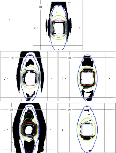
Table IV. Multiple-beam IMRT test. Percentage area of the ROI (29141 calc. points) which failed the 3% dose and 3 mm DTA criteria i.e. with γ ≥ 1. Data refers to three horizontal planes at different depths; for all possible TPS, algorithm and energy combinations. (PB … pencil beam; CC … collapsed cone).
Discussion
The main objective of the study was to investigate the impact of dose calculation algorithms on IMRT treatment plans in lung and to compare quantitative results of IMRT plans with simple single-beam and multiple-conformal-beam arrangements. Results presented in , which were based on ionization measurements, demonstrate a risk of target underdosage between 3–5% when using the PB algorithm (including EPL inhomogeneity correction) for dose calculation.
Multiple segments used for ‘step-&-shoot’ IMRT dose delivery can be very irregular and complex in shape, which may influence dose calculation accuracy and ionization measurements. For example, one can expect smaller deviations for single- and multiple-conformal beam geometries, where a detector is always centered in a (relatively) larger field, compared to IMRT where the detector can be partly shaded. As presented previously in our treatment planning study Citation[9], Helax-TMS and BrainSCAN IMRT solutions with similar overall dose distributions can differ substantially with respect to segments per beam and total number of MU. In the present dosimetric study, the BrainSCAN IMRT plan was composed of 74 segments in total (for five IM beams) whereas Helax-TMS required only 19. The respective number of MU was larger for the BrainSCAN IMRT plan (326 vs. 221). Besides the high number of segments, the segments themselves were generally much more complex in shape and size, some of them even reaching a beamlet size (3×4 mm2). Consequently, deviations of isocentric ionization chamber measurements for BrainSCAN were expected to be larger than those of Helax-TMS. This trend was not observed and the deviation of the BrainSCAN IMRT plan for 6 MV was almost identical with that of the Helax-TMS IMRT plan based on the PB calculation. Moreover, BrainSCAN single-beam experiments showed larger deviations compared to those of IMRT. Excellent results were obtained for all tests including IMRT when calculations were made utilizing the CC algorithm. It can be concluded that deviations for ionization-based dosimetry in IMRT beams are influenced to a larger extent by the dose calculation algorithm than by the detector volume effects.
Nevertheless, the spatial resolution of a detector used for commissioning can have an impact on relative dose distribution. It is difficult to distinguish between the influence of detector volume effects and that of dose calculation, unless basic beam data used in the TPS are measured with the same detector as used for dosimetric studies. This was not the case for the present study. A small volume ionization chamber was used during commissioning and films were used for 2D dosimetry. The detector volume effect could explain the remaining deviations of the CC-recalculated dose distributions at the beam edge (). In addition, state-of-the-art radiation therapy requires dose calculation with a millimeter resolution. That is particularly the case for micro-MLC applications. Therefore it is reasonable to verify dose distributions using detectors with clinically relevant spatial resolution regardless of dose calculation aspects.
Table V. Multiple-beam IMRT tests. Percentage of calculation points with γ ≥ 1 within the ROI (29141 calc. points) in the isocenter plane for five different TPS-calculated dose bins (dTPS). Last two rows correspond to the number of points with γ ≥ 1 presented in .
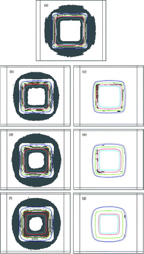
All γ results showed a substantial improvement when applying the CC algorithm. However, it is difficult to quantify any potential clinical impact of a deviation between measurement and calculation. A ROI fraction with γ ≥ 1 can not be directly used as acceptance criteria unless a ROI is further specified. In addition, γ values do not indicate whether the dose deviation is positive or negative, which further complicates the estimation of potential clinical consequences. In clinical situations the dose calculation accuracy at distances far from the isocenter (e.g. at positions close to an organ at risk) can be crucial. Therefore, the ROI in the present study was chosen ‘as large as possible’ to cover most of the dose calculation points. A more detailed investigation of γ results is presented in , where five dose bins were used to categorize deviations. While dose distributions calculated with the PB model showed most discrepancies in low (<50%) and high (>90%) dose regions, for the CC based calculations almost all deviations were observed in high dose gradient (20–80%) regions. At relative dose levels >90% almost no deviations with γ > 1 was observed for the CC plans. This trend was also present in single- and multiple-conformal-beam tests (see a-g for single beam test).
Figure 3. Coronal γ distributions at the isocentric plane of the lung phantom for single-beam arrangement: Grey areas indicate dose calculation points with γ ≥ 1 i.e. not meeting 3% dose or 3 mm DTA criterion. γ distribution is displayed on background of TPS-calculated (dotted lines) and film-measured (solid lines) isodoses (20%, 50%, 80% and 90%). Rectangles indicate the ROI chosen for γ analysis. a) BrainSCAN 6MV PB (pencil beam) b) Helax-TMS 6MV PB c) Helax-TMS 6MV CC (collapsed cone) d) Helax-TMS 10MV PB e) Helax-TMS 10MV CC f) Helax-TMS 25MV PB g) Helax-TMS 25MV CC.
When using the CC algorithm, both ionization and film measurement for 6 and 10 MV single-beam tests showed better but still relatively large deviations between measurements and dose calculation compared with the multiple-beam geometries. In the γ analysis this is reflected in considerable different results for the deepest measurement plane. This could be probably explained by the phantom design. Even with the CC algorithm problems can still exist with the depth dose modeling of so many build-up and build-down interfaces. It could be expected that the single-beam geometry is more sensitive to this phenomena than the multiple-beam geometry. To the knowledge of the authors no 2D investigations outside of the target existed and a more detailed discussion would require investigation of the implementation of the algorithm, especially with respect to the beam quality.
In summary, IMRT plans calculated with the PB or the CC algorithm have the same accuracy as conformal plans. The data showed no influence of small segments on the accuracy. IMRT plans recalculated with the CC algorithm yield much better agreement with measurements especially at higher energies. Such recalculated plans, however, do not necessarily fulfill the requested treatment aims specified during optimization. In uniform-intensity conformal therapy field sizes can be adapted interactively after dose recalculation. For IMRT there is no such option. Therefore, for IMRT in lung, dose calculation during optimization needs to be based on more accurate algorithms. Such gain in accuracy is naturally compromised by increased calculation times. An effective solution to this problem was presented by Laub et al. Citation[16]. They proposed to use a PB algorithm to compute the fluence updates for a converging sequence of Monte Carlo dose distributions; i.e. first a dose-per-unit fluence operator is calculated with a PB algorithm and then a Monte Carlo dose distribution is applied. On the basis of the Monte Carlo dose distribution, the fluence was modified during the next iterative step. In the next step, the Monte Carlo dose distribution is updated according to the new fluence profile, and so forth. The method was shown to converge to the global minimum corresponding to the Monte Carlo dose computation.
Compared to uniform-intensity conformal radiotherapy, for IMRT there is an increased risk of clinical impact in case of imprecisely calculated dose distributions and dose escalation. The advantages of IMRT like improved conformity and intra-target dose control should be counterbalanced with possible inaccuracies, especially when applied for targets in the lung (e.g. connected dose escalation) and until no superior dose calculation algorithms are involved in the iterative optimization process. When only PB algorithm with simple inhomogeneity correction is used, lower energy photon beams should be utilized.
Acknowledgements
All data presented was obtained at the Medical University Vienna/AKH Vienna. Pavel Dvorak was supported by the EC project HCMPT – 2001–0318. The authors would like to thank Brainlab for providing various software modules for data and image transfer.
References
- Liu HH, Wang X, Dong L, Wu Q, Liao Z, Stevens CW, et al. Feasibility of sparing lung and other thoracic structures with intensity-modulated radiotherapy for non-small-cell lung cancer. Int J Radiat Oncol Biol Phys 2004; 58: 1268–79
- Murshed H, Liu HH, Liao Z, Barker JL, Wang X, Tucker SL, et al. Dose and volume reduction for normal lung using intensity-modulated radiotherapy for advanced-stage non-small-cell lung cancer. Int J Radiat Oncol Biol Phys 2004; 58: 1258–67
- Underwood LJ, Murray BR, Robinson DM, Colin Field G, Roa WH. An evaluation of forward and inverse radiotherapy planning using Helax TMS (version 6.0) for lung cancer patients treated with RTOG 93-11 dose escalation protocol. Med Dosim 2003; 28: 167–70
- Knoos T, Ahnesjo A, Nilsson P, Weber L. Limitations of a pencil beam approach to photon dose calculations in lung tissue. Phys Med Biol 1995; 40: 1411–20
- Engelsman M, Damen EMF, Koken PW, van ‘t Veld AA, van Ingen KM, Mijnheer BJ. Impact of simple tissue inhomogeneity correction algorithms on conformal radiotherapy of lung tumors. Radiother Oncol 2001; 60: 299–309
- Laub WU, Bakai A, Nuesslin F. Intensity modulated irradiation of a thorax phantom: Comparisons between measurements, Monte Carlo calculations and pencil beam calculations. Phys Med Biol 2001; 46: 1695–705
- Scholz C, Nill S, Oelfke U. Comparison of IMRT optimization based on a pencil beam and a superposition algorithm. Med Phys 2003; 30: 1909–13
- AAPM Report of Task Group No. 65 of the Radiation Therapy Committee of the American Association of Physicists in Medicine 2004, Tissue inhomogeneity corrections for megavoltage photon beams AAPM Report NO. 85, 1–135.
- Dvorak P, Georg D, Bogner J, Kroupa B, Dieckmann K, Poetter R. Impact of IMRT and leaf width on stereotactic body radiotherapy of liver and lung lesions. Int J Radiat Oncol Biol Phys 2005; 61: 1572–81
- Ahnesjo A, Aspradakis MM. Dose calculations for external photon beams in radiotherapy (topical review). Phys Med Biol 1999; 44: R99–R155
- Lacer J, Solberg TD, Promberger C. Comparative behaviour of the dynamically penalized likelihood algorithm in inverse radiation therapy planning. Phys Med Biol 2001; 46: 2637–63
- IAEA 2000 Absorbed Dose Determination in external beam radiotherapy: An international code of practice for dosimetry based on standards of absorbed dose to water. IAEA TRS 398.
- Low DA, Harms WB, Mutic S, Purdy JA. A technique for the quantitative evaluation of dose distributions. Med Phys 1998; 25: 656–61
- Georg D, Kroupa B, Winkler P, Poetter R. Normalized sensitometric curves for the verification of hybrid IMRT treatment plans with multiple energies. Med Phys 2003; 30: 1142–50
- Stock M, Kroupa B, Georg D. Interpretation and evaluation of the γ index and the γ index angle for the verification of IMRT hybrid plans. Phys Med Biol 2005; 50: 399–411
- Laub W, Alber M, Birkner M, Nuesslin F. Monte Carlo dose computation for IMRT optimization. Phys Med Biol 2000; 45: 1741–54