Abstract
Purpose. To quantify the improvements in online target localization using kV cone beam CT (CBCT) with deformable registration. Methods and material. Twelve patients treated under a 6 fraction liver cancer radiation therapy protocol were imaged in breath hold using kV CBCT at each treatment fraction. The images were imported into the treatment planning software and rigidly registered by fitting the liver, identified on the daily kV CBCT image, into the liver contours, previously drawn on the planning CT. The liver was then manually contoured on each CBCT image. Deformable registration was automatically performed, aligning the CT liver to the liver on each CBCT image using MORFEUS, a biomechanical model based deformable registration algorithm. The tumor, defined on planning CT, was mapped onto the CBCT, through MORFEUS. The center of mass (COM) displacement of the tumor was computed. Results. The mean (SD) displacement magnitude (absolute value) of the COM following deformable registration was 0.08 (0.07), 0.10 (0.11), and 0.10 (0.17) cm in the left-right (LR), anterior-posterior (AP), and superior-inferior (SI) directions, respectively. The maximum displacement of the COM was 0.34, 0.65, and 0.97 cm in the LR, AP, and SI directions, respectively. Fifteen percent of the treatment fractions had a COM displacement of greater than 0.3 cm and 33% of patients had at least 1 fraction with a displacement of greater than 0.3 cm. The deformable registration, excluding the manual contouring of the liver, was performed in less than 1 minute, on average. Discussion. Rigid registration of the liver volume between planning CT and verification kV CBCT localizes the tumor to within 0.3 cm for the majority (66%) of patients; however, larger offsets in tumor position can be observed due to liver deformation.
Precision in tumor localization at the time of treatment has seen significant advancements over the last decade. Starting with 2D MV portal images, bone anatomy was viewed and aligned prior to treatment Citation[1]. Implanting fiducial markers allowed soft tissue surrogates to be aligned at the time of treatment Citation[2]. The introduction of kV portal imaging allowed for some soft tissue guidance as well as smaller fiducial markers to replace the larger markers required for visualization with MV imaging Citation[2–4]. The advent of in-room volumetric imaging, including kV cone-beam CT (kV CBCT), MV CBCT, and tomographic images has allowed an unprecedented view of the soft tissue anatomy in the treatment position immediately prior to radiation delivery Citation[5–8].
Developments in image registration have followed this progression of online image guidance. Manual and semi-automatic registration of boney alignment allowed 2D portal images to provide guidance for the patient's treatment Citation[9–12].
Simulated 3D image registration by aligning both 2D planar images and developing further automation in image alignment was used to improve the accuracy and efficiency of online image guidance. Volumetric images provided the opportunity to improve registration by alignment of the entire image or the volumetric region of interest (ROI) at the time of treatment with the planning CT. However, with the abundance of information available in volumetric imaging, it became obvious that the patient was not always able to be registered to the reference geometry using rigid registration alone, as internal anatomy often changed in position, volume and/or shape compared to that from the planning CT.
The development of deformable registration techniques has primarily focused in the treatment planning space, aligning multi-modality images and temporal images to provide a more consistent and complete description of the patients’ anatomy and physiological motion. Deformable registration techniques can be broadly divided into two classes, those that are driven by alignment of the image intensity and those that rely on biomechanical models. Both techniques have been shown to have accuracy on the order of the voxel resolution. One benefit of the biomechanical approach is its accuracy should remain constant even in the presence of low and/or differing contrast images, provided that the boundary conditions can be appropriately defined. Consistent algorithm performance in low contrast is particularly important for IGRT of liver cancer, as the majority of these tumors are not visible without the administration of IV contrast prior to imaging, which is typically reserved for imaging performed during treatment planning.
The application of deformable registration for treatment guidance has been described for head and neck and prostate cancers Citation[13–15]. Previous work by our institution has indicated the potential for the application of deformable registration for liver radiotherapy treatment guidance by quantifying the presence of deformation of the liver between the treatment planning CT and the daily kV CBCT following rigid registration alone Citation[16]. The purpose of this research is to quantify how this organ deformation translates into residual errors in the tumor position during image guided localization of the target when the tumor cannot be visualized on the in-room images. The improvement in liver cancer localization accuracy is quantified using a biomechanical-based deformable registration technique over rigid body registration alone.
Methods and materials
Patient data
Twelve patients treated under a research ethics board (REB) approved hypofractionated liver study were used for this analysis. An individualized dose, based on the normal tissue complication probability, was delivered in 6 fractions under breath hold guidance using the active breathing coordinator, with online image guidance using orthogonal imaging as previously described Citation[16], Citation[17]. A breath hold kV CBCT image was planned to be acquired in treatment position for all fractions at 120 kVp, 0.8 mAs/projection, 25.6 cm/25.6 cm axial/longitudinal field of view at a rate of 2.7 frames per second, digitized to 16 bits in 1024×1024 pixels. The 360° rotation, which acquires ∼157 projections in 1 minute, was performed in three 20 second breath holds. In an offline study, the kV CBCT image was aligned to the planning CT using rigid registration to best align the liver, shown on the kV CBCT image, into the contour of the liver from the planning CT image, which were overlaid onto the kV CBCT image. The liver was then contoured on the kV CBCT image by copying the planning CT liver contour and editing the contour to correctly indicate the liver outline on the kV CBCT. The copying process was used to minimize contouring error.
The number of tumors per patient ranged from 1 (n = 6) to 6 (n = 1) The location of the tumors varied between patients and included the dome, left lobe, and inferior extent. The tumors were visible on the planning CT images, which were obtained with IV contrast, but were not visible on the kV CBCT images, which were not obtained with IV contrast.
Deformable registration
A biomechanical model-based deformable registration technique developed in house, MORFEUS, was used for analysis Citation[18], Citation[19]. The algorithm, illustrated in , converts the contours of the liver and tumor contours into finite element models (FEM), which consist of a series of nodes, or points in space, connected together to form tetrahedrons. These tetrahedrons describe the entire volume of the liver and tumor. Linear elastic material properties are assigned to the FEM of the liver and tumor. The liver is assigned a Young's Modulus (descriptor of stiffness) of 7.8 kPa and a Poisson's ratio (descriptor of compression) of 0.450 Citation[20]. The tumor is assigned a Young's Modulus of 78 kPa, a factor 10 stiffer than the liver, and a Poisson's ratio of 0.450. The contour of the liver from the CBCT scan is converted into a FEM consisting of only nodes on the surface, connected to form triangular elements to describe the 3D surface of the liver.
Figure 1. The MORFEUS Algorithm: Contours of the liver and tumor from the planning CT are converted into a volumetric mesh with assigned material properties. Contours of the liver from the kV CBCT are converted into a surface mesh. Boundary conditions are determined from the surface correlation of the livers, which generates boundary conditions. These boundary conditions are used to solve for the deformation map of the entire liver volume, including the tumor, using finite element analysis.
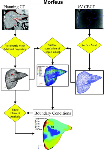
Boundary conditions are determined by aligning the surface of the liver between the two images. The alignment of the surface of the liver is performed automatically by converting the FEM of the CBCT liver into a parametric surface representation then projecting the nodes on the surface of the FEM of the CT liver onto this surface. This node to surface mapping does not restrict the nodes on the surface of the FEM of the liver to a specific node of the FEM of the CBCT liver. The surface projection is performed using HyperMorph, a guided-surface projection algorithm in HyperWorks (Altair Engineering, Troy MI). The internal structure of the liver, including the tumor, is determined according to the biomechanical material properties that are defined and is determined from a finite element analysis (ABAQUS, ABAQUS Inc, Pawtucket, RI). It is important to note that the motion of the tumor is not directly aligned to the tumor on the kV CBCT, which is not visible, but is aligned based on the biomechanical model that is established from the planning CT image, where the tumor is visible. The method is therefore independent of the contrast in the images, as long as it is sufficient to contour the organ of interest on both images. The technique has been previously described in detail and the accuracy reported for liver image registration (0.4 cm vector magnitude residual error Citation[21], 0.14–0.20 cm residual error in the LR, AP, and SI direction Citation[19]).
Data analysis
Rigid registration was performed by fitting the liver, as presented on the CBCT, into the contour generated from the liver on the planning CT. Deformable registration, using MORFEUS, was performed to align the liver and tumor defined on the planning CT to each CBCT after the initial rigid registration, in order to determine any additional improvement in tumor positioning from considering deformation in the liver-liver image alignment process for IGRT. The change in the center of mass (COM) of the tumor was determined from the deformable registration. The change in COM represents the residual error in tumor position following rigid registration. The new position of the COM following deformable registration reflects the position of the COM of the tumor at the time of treatment. The change in COM indicates the improved precision in target localization following deformable registration.
The change in COM was determined for each tumor, when multiple tumors were treated, and for each of the treatment fractions where a kV CBCT image was acquired. Differences in the change in COM for tumors within the same patient, during the same fraction were analyzed.
Results
Deformable registration was performed on kV CBCTs obtained from 66 fractions from 12 patients.
The change in tumor COM is shown in . The average absolute change in COM position across all tumors in all patients was 0.1 cm or less in each direction. The standard deviation was 0.07, 0.11, and 0.17 cm in the left-right, anterior-posterior, and superior-inferior directions, respectively. The maximum magnitude of change in COM, however, was 0.34, 0.65, and 0.97 cm in the left-right, anterior-posterior, and superior-inferior directions, respectively. a illustrates a patient who had a tumor COM displacement of −0.36 cm LR, −0.29 cm AP, and −0.19 cm SI displacement following deformable registration at fraction 3 of their 6 fraction treatment. b illustrates the motion and minor deformation of the tumor at this treatment fraction.
Figure 2. Example of the residual deformation of the liver and tumor between the planning CT (shown in the colorwash) containing the delineated tumor (visible in the left lobe) and the liver defined on the kV CBCT (shown in the blue mesh). The displacements correspond to the vector magnitude of the displacements defined from the deformable registration using MORFEUS. (b) The vector displacement of the tumor, identified on the planning CT, between the position on the planning CT and the kV CBCT on treatment fraction 3. The change in COM was −0.36, −0.29, and 0.29 cm in the left-right, anterior-posterior, and superior-inferior directions, respectively.
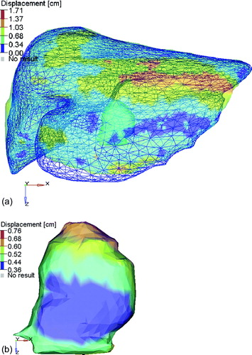
Table I. Change in tumor COM statistics [cm].
Four of the 12 patients analyzed (33%) had at least 1 of the treatment fractions analyzed with a change in tumor COM of greater than 0.3 cm in one direction. Fifteen percent of the treatment fractions investigated had a change in COM of greater than 0.3 cm in one direction. The location of the tumors of these four patients included the dome of the liver, the geometric center of the liver, the middle and inferior extent of the liver, and the dome and left lobe.
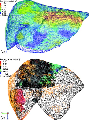
Six of the 12 patients had more than 1 tumor (range: 2–6 tumors). The average difference in the vector magnitude of the change in COM of the tumors within the same patient at 1 fraction was 0.03 cm (SD = 0.12 cm), suggesting little overall liver deformation in the region of the tumors for these patients. The range of differences was −0.17 to 0.95 cm. Two of the six patients with multiple tumors had a difference in the magnitude of the change in COM of the tumors in any direction of greater than 0.3 cm. One patient had two tumors, one in the middle of the liver and the other in the inferior tip of the liver. In two of the fractions, the COM of the tumors moved in opposite directions, the colorwash for one of the fractions is shown in a. b highlights the LR motion of the liver and tumors. The difference in COM is predominantly due to a LR shift of the tip of the liver and a small change in the shape of the dome of the liver. The second patient had six tumors, the predominant ones in the dome and the lower left lobe. In all five of the fractions the COM of these two tumors differed by more than 0.5 cm in the SI direction, in two of the five fractions, the COM differed by more than 0.3 cm in the AP direction, and in one of the fractions, the COM differed by more than 0.3 cm in the LR direction. The colorwash for one of the fractions is shown in a and b, where changes in the inferior extent of the liver can be noticed, due to a flattening of this region as well as smaller changes in the dome of the liver.
Figure 3. The planning CT liver (colorwash of the vector magnitude of the difference between the two liver models) and the CBCT liver at fraction 5 (blue mesh). The tumors (shown as solid shadows within the colorwash) are in the middle and the lower tip of the liver. Differences in the position of the tip of the liver and the dome of the liver can be seen. Alignment of the left lobe of the liver indicates that rotation, as opposed to deformation, could account for the disagreement. (b) The planning CT liver (colorwash of the left-right component of the difference between the two liver models) and the CBCT liver at fraction 5 (black mesh). The tumors (shown as solid shadows within the colorwash) are seen in the middle and the lower tip of the liver.
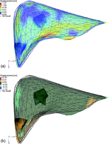
Figure 4. The planning CT liver (colorwash of the vector magnitude of the difference between the two liver models) and the CBCT liver at fraction 3 (blue mesh). (b) The planning CT liver (mesh colorwash of the SI component of the difference between the two liver models) and the CBCT liver at fraction 3 (not shown). The tumors (shown as solid colorwashes) are in the dome and left lobe of the liver.
Discussion
The role of deformable registration to improve precision and accuracy in image guided treatment for liver tumors not visible using non contrast in-room volumetric image guidance has been explored. Although the majority of 66 treatment fractions analyzed (85%) had a change in COM of the tumor following deformable registration of less than 0.3 cm, 33% of the patients had at the change in COM of the tumor greater than 0.3 cm in at least 1 of their 6 fractions. In stereotactic body radiotherapy (SBRT) where the dose delivered per fraction is high as well as the dose gradient, a systematic geometric error of 0.3 cm or greater in one fraction may have clinically relevant dosimetric consequences. The dosimetric effect of these residual errors is the subject of ongoing research.
The difference in change in COM of tumors within the same patient, although less common, poses a unique problem, as the optimal correction cannot be applied to each tumor. The best correction strategy will likely be a combination of ensuring coverage of the both tumors and sparing the critical structures.
The variation in position within the liver of the tumors that had a change in COM of greater than 0.3 cm indicates that the effect of residual error following rigid registration may affect patients regardless of tumor location. The rigid registration of the liver was performed to provide a best fit for the entire liver. Focusing the attention of the rigid registration on the region of the liver containing the tumor may reduce the residual error in the COM of the tumor. It is unlikely that this would eliminate the residual error for all cases as deformation can be complex in a local environment (such as deforming the shape of the dome of the liver due to differences in breathing patterns and local deformation of the left lobe of the liver due to changes in stomach filling). This complex deformation can be difficult to convert to a best-fit rigid registration based on the region of the liver containing the tumor when the tumor is on the border of the region being locally deformed or in the case of multiple tumors.
The accuracy of the deformable registration cannot be quantified for this study, as the tumor and naturally occurring internal fiducials (i.e. vessel bifurcations) were not visible on the non-intravenous contrast kV CBCT images. One can expect, however, that the accuracy is comparable to the previously reported accuracy, using CT to MR registration where contrast was used in both liver images allowing bifurcations to be identified. One limiting factor is the uncertainty in contouring the liver. The degree of this uncertainty and its effect on accuracy is the study of current research. Preliminary investigations, 2 observers on 5 CBCT images, indicate that for interobserver contour variations with a standard deviation of 1 mm in each direction the average absolute difference in tumor COM determined from each of the observers contours is within 1 mm in each direction.
The application of the proposed technique into the clinic is limited by its efficiency. MORFEUS currently takes an average of less than 1 minute to perform the registration on a single, tumor bearing organ, after the organ of interest is delineated. The rate limiting step is the generation of the contours on the CBCT image. The development of automated contouring algorithms Citation[22–25] promises to reduce this burden, opening the door for improvements in tumor targeting in IGRT through deformable registration.
This study concludes that although the majority of liver cancer patients do not require deformable registration to ensure an accuracy in image guidance of less than 3 mm, one-third of the patients would benefit from deformable registration IGRT in at least 1 of their 6 fractions. Residual deformation following rigid registration was shown to result in a change in center of mass of the tumor of greater than 3 mm in some cases (15% of the fractions investigated), indicating that care should be taken when changes in the shape of the tumor bearing organ are observed between the planning CT and online volumetric image. The feasibility of a biomechanical model based deformable registration algorithm, which can leverage the relationship between the tumor and the tumor-bearing organ established from the diagnostic quality planning CT for purposes of tumor mapping in the absence of a high contrast secondary image, has been demonstrated.
Acknowledgements
Research supported in part by grants from the National Cancer Institute of Canada, National Cancer Institute of Canada – Terry Fox Foundation, and Elekta Oncology Systems. Clinical trial supported in part from Canadian Cancer Society.
References
- Dong L, Boyer AL. An image correlation procedure for digitally reconstructed radiographs and electronic portal images. Int J Radiat Oncol Biol Phys 1995; 33: 1053–60
- Litzenberg D, Dawson LA, Sandler H, Sanda MG, McShan DL, Ten Haken RK, et al. Daily prostate targeting using implanted radiopaque markers. Int J Radiat Oncol Biol Phys 2002; 52: 699–703
- Dawson LA, Brock KK, Kazanjian S, Fitch D, McGinn CJ, Lawrence TS, et al. The reproducibility of organ position using active breathing control (ABC) during liver radiotherapy. Int J Radiat Oncol Biol Phys 2001; 51: 1410–21
- Eccles C, Brock KK, Bissonnette JP, Hawkins M, Dawson LA. Reproducibility of liver position using active breathing coordinator for liver cancer radiotherapy. Int J Radiat Oncol Biol Phys 2006; 64: 751–9
- Jaffray DA, Siewerdsen JH. Cone-beam computed tomography with a flat-panel imager: Initial performance characterization. Med Phys 2000; 27: 1311–23
- Mackie TR, Holmes T, Swerdloff S, Reckwerdt P, Deasy JO, Yang J, et al. Tomotherapy: A new concept for the delivery of dynamic conformal radiotherapy. Med Phys 1993; 20: 1709–19
- Ruchala KJ, Olivera GH, Kapatoes JM, Schloesser EA, Reckwerdt PJ, Mackie TR. Megavoltage CT image reconstruction during tomotherapy treatments. Phys Med Biol 2000; 45: 3545–62
- Ford EC, Chang J, Mueller K, Sidhu K, Todor D, Mageras G, et al. Cone-beam CT with megavoltage beams and an amorphous silicon electronic portal imaging device: Potential for verification of radiotherapy of lung cancer. Med Phys 2002; 29: 2913–24
- Moseley J, Munro P. A semiautomatic method for registration of portal images. Med Phys 1994; 21: 551–8
- Hristov DH, Fallone BG. A grey-level image alignment algorithm for registration of portal images and digitally reconstructed radiographs. Med Phys 1996; 23: 75–84
- Plattard D, Soret M, Troccaz J, Vassal P, Giraud JY, Champleboux G, et al. Patient set-up using portal images: 2D/2D image registration using mutual information. Comput Aided Surg 2000; 5: 246–62
- Brock KK, McShan DL, Balter JM. A comparison of computer-controlled versus manual on-line patient setup adjustment. J Appl Clin Med Phys 2002; 3: 241–7
- Foskey M, Davis B, Goyal L, Chang S, Chaney E, Strehl N, et al. Large deformation three-dimensional image registration in image-guided radiation therapy. Phys Med Biol 2005; 50: 5869–92
- Mohan R, Zhang X, Wang H, Kang Y, Wang X, Liu H, et al. Use of deformed intensity distributions for on-line modification of image-guided IMRT to account for interfractional anatomic changes. Int J Radiat Oncol Biol Phys 2005; 61: 1258–66
- Lu W, Olivera GH, Chen Q, Ruchala KJ, Haimerl J, Meeks SL, et al. Deformable registration of the planning image (kVCT) and the daily images (MVCT) for adaptive radiation therapy. Phys Med Biol 2006; 51: 4357–74
- Hawkins MA, Brock KK, Eccles C, Moseley D, Jaffray D, Dawson LA. Assessment of residual error in liver position using kV cone-beam computed tomography for liver cancer high-precision radiation therapy. Int J Radiat Oncol Biol Phys 2006; 66: 610–9
- Dawson LA, Eccles C, Bissonnette JP, Brock KK. Accuracy of daily image guidance for hypofractionated liver radiotherapy with active breathing control. Int J Radiat Oncol Biol Phys 2005; 62: 1247–52
- Brock KK, Dawson LA, Sharpe MB, Moseley DJ, Jaffray DA. Feasibility of a novel deformable image registration technique to facilitate classification, targeting, and monitoring of tumor and normal tissue. Int J Radiat Oncol Biol Phys 2006; 64: 1245–54
- Brock KK, Sharpe MB, Dawson LA, Kim SM, Jaffray DA. Accuracy of finite element model-based multi-organ deformable image registration. Med Phys 2005; 32: 1647–59
- Kruse SA, Smith JA, Lawrence AJ, Dresner MA, Manduca A, Greenleaf JF, et al. Tissue characterization using magnetic resonance elastography: Preliminary results. Phys Med Biol 2000; 45: 1579–90
- Voroney JP, Brock KK, Eccles C, Haider M, Dawson LA. Prospective comparison of computed tomography and magnetic resonance imaging for liver cancer delineation using deformable image registration. Int J Radiat Oncol Biol Phys 2006; 66: 780–91
- Kaus MR, Warfield SK, Nabavi A, Black PM, Jolesz FA, Kikinis R. Automated segmentation of MR images of brain tumors. Radiology 2001; 218: 586–91
- Joshi S, Pizer S, Fletcher PT, Yushkevich P, Thall A, Marron JS. Multiscale deformable model segmentation and statistical shape analysis using medial descriptions. IEEE Trans Med Imaging 2002; 21: 538–50
- Park H, Bland PH, Meyer CR. Construction of an abdominal probabilistic atlas and its application in segmentation. IEEE Trans Med Imaging 2003; 22: 483–92
- Davis BC, Foskey M, Rosenman J, Goyal L, Chang S, Joshi S. Automatic segmentation of intra-treatment CT images for adaptive radiation therapy of the prostate. Med Image Comput Comput Assist Interv Int Conf Med Image Comput Comput Assist Interv 2005; 8(Pt 1)442–50