
 ?Mathematical formulae have been encoded as MathML and are displayed in this HTML version using MathJax in order to improve their display. Uncheck the box to turn MathJax off. This feature requires Javascript. Click on a formula to zoom.
ABSTRACT
High entropy alloys (HEAs), consisting of five or more elements with nearly equal atomic composition with one another (5–35%), are new-generation alloys that have attracted significant interest since their advent in 2004 because of their unique structural and mechanical properties and thermodynamic and chemical stability. Some characteristics, including high mechanical strength at elevated temperatures, high ductility and fracture toughness at cryogenic temperatures and high corrosion, erosion and wear resistance, have been demonstrated for HEAs that outperform traditional alloys and superalloys. Laser-cladding (LC) is an additive manufacturing technique that has good feasibility in designing and processing HEAs for advanced structural components and protective coatings. This overview provides a glimpse of recent advances in LC of HEAs in terms of design fundamentals, metallurgical phase and microstructure, specific properties for advanced coating applications and the effect of ceramic particles reinforcement in LC deposition of HEA coatings.
Introduction
Traditional design of metals and alloys is based on one or two dominant major alloying elements. By introducing additives with significantly lower atomic content in the matrix phase formed by the dominant elements, the microstructure and thus the mechanical performance of the alloys can be engineered. It is generally believed that an increase in the composition of the additives could induce precipitation of intermetallic phase that in turn degrade the mechanical, thermal, and/or chemical properties of traditional alloys (TAs)[Citation1]. The advent of high entropy alloys (HEAs) has revolutionised the alloy design of TAs [Citation2,Citation3]. Instead of clear distinction between solute (additives) and solution (dominant elements) of TAs, HEA consists of five or more dominant elements with nearly equal atomic composition with one another, typically in the range of 5–35%, forming a randomly configurated alloy without difference between solute and solution[Citation1]. The high mixing entropy, contributed by the increased number of elements with nearly equal composition, tends to decrease the Gibbs free energy of atomic mixing and in turn stabilises the solid solution against intermetallic phase precipitation [Citation1–3].
The random mixing of atoms with mismatch size gives rise to large lattice distortion and reduced atomic diffusion of HEAs. Such unique thermodynamic and microstructural properties result in excellent alloy performance including high thermal stability and mechanical strength at high temperature, high ductility and fracture toughness at cryogenic temperatures, high hardness and resistance to irradiation, and excellent resistance to corrosion, erosion and wear degradation. These properties of HEAs, together with the rapid expansion of additive manufacturing (AM) of metallic alloys in the past decade, have attracted increased interest in recent years [Citation4,Citation5].
Laser-cladding (LC) is a typical AM technique that applies a laser beam to heat and melt feedstock on the surface of the workpiece. The rapid heating and cooling of the melt pool associated with the laser process results in metallurgical fusion of feedstock into the surface with mitigated workpiece distortion. Typically, laser heating and feedstock feeding are concentrically integrated in a LC head that can be feasibly equipped and precisely controlled by robotic or computer numerical control (CNC) platform for advanced cladding process. By optimising the processing parameters such as laser power, feeding rate, scanning speed, stepover distance, nozzle to surface distance, etc., structural defects, e.g. thermal cracking, microstructural pores, etc., can be eliminated and the substrate dilution can be minimised during the LC process[Citation6]. Hybrids of LC and cold-working process, e.g. robotic hammer peening [Citation7–9], in monolithic process can provide additional benefits for microstructural engineering and thus enhance the performance of AM alloys and/or coatings [Citation5,Citation10].
Many alloys, including stainless steels (SS), Ni-based superalloys, Ti-based alloys, etc., can now be directly deposited by LC without generating thermal cracks [Citation11–13]. Meanwhile, porosity of LC deposited alloys can be significantly reduced by engineering the feedstock in conjunction with the optimisation of LC process. Various in situ data collection techniques have been developed along with machine learning to optimise LC process and accelerate the design and prototyping of new alloys. A brief review of the literature suggests that LC has been intensively studied in recent years for developing HEAs in both areas of AM and protective coatings[Citation14]. It is also indicated that when prototyping novel HEA designs, except for the equipment cost, LC has the best advantage of being cost-effective in both material- and time-consuming as compared to traditional fabrication methods [Citation5,Citation15]. In this overview, we briefly describe the design fundamentals, process, structural properties and functional performance of HEAs with particular focus on recent advances in LC of HEA for protective coatings.
Concept of HEA and general guidelines for designing HEAs
Since its advent in 2004, the concept of HEAs continues to evolve with new experimental findings [Citation2,Citation3]. A general definition of HEA is that the alloy consists of five or more principal elements, with their atomic composition in the range of 5–35%, randomly mixed in crystal lattice to achieve a high degree of disorder, i.e. high configurational entropy. The entropy of atomic mixing in HEAs is described byCitation[2]:
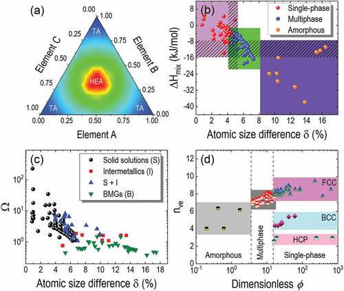
where, R is the gas constant, n is the number of the constituent elements and xi is the atomic composition of i element. In ideal case, the maximum ΔSmix is obtained when xi = 1/n. For example, presented in ) is the ΔSmix of a three-element alloy ABC following EquationEq. (1(1),
(1), ), which shows that the highest ΔSmix is located at the centre of the ternary contour map where A, B and C have equal atomic composition of 33.3%. However, experimental observations suggested that besides solid solution phases, multi-component HEAs may form intermetallic compounds and amorphous, i.e. metallic glass phases. In this regard, a two-parameter scheme was proposed to describe phase selection of HEAs[Citation1]. They are enthalpy of mixing ΔHmix and atomic size difference δ[Citation16].
Figure 1. Concept and basic design principles for HEAs. (a) Typical contour of ΔSmix for a ternary alloy system. The corner regions with lower ΔSmix, indicating traditional alloys (Tas) based on one or two principal elements while the centre region with higher ΔSmix, indicating the equimolar ternary HEAs. (b) Plots ΔHmix as a function of δ, guiding the phase selection of HEAs. (c) Plots of Ω as a function of δ, guiding the phase selection of HEAs. (d) Plots of VEC as a function of ϕ for the phase selection of HEAs. Partly reproduced from Ref. 3 © 2016 Elsevier.
In EquationEquation (2)(2)
(2) ,
is the regular solution interaction parameter between the number i and j elements and
is the enthalpy of mixing in binary liquid alloys. Presented in ) are typical phase distribution of solid solution observed in HEAs, where single-phase solid solution of HEAs occurs at both lower ΔHmix and lower δ. An increase in the negative ΔHmix leads to multiple phases, consisting of solid solution (S) and intermetallic phases (I), and eventually metallic glass. However, it can be seen in ) that overlaps, as indicated by the patterns, are existing in the phase selection of HEAs based on ΔHmix and δ. Alternatively, a combination of Ω and δ was proposed to guide the phase selection in HEA design withCitation[16]:
An assumption that the difference in Gibbs free energy between solid and liquid alloys is proportional to the free energy of mixing (ΔGmix) in the liquid alloy leads to [Citation1,Citation16]:
The combination of EquationEquatoins (4)(4).
(4). and (Equation5
(5).
(5). ) shows that an increase in Ω, i.e. by increasing ΔSmix and/or decreasing the value of ΔHmix, tends to enhance the single-phase while suppressing the intermetallic phases, i.e. stabilising single-phase solid solution against mixing of intermetallic phases [Citation1,Citation16]. Experimental results showed that the overlap of the phase distribution still exists in the (δ, Ω) map, as shown in ). In this regard, parameters ϕ and nve were further proposed to guide the phase selection in HEA design. ϕ is associated with generality of ST in formulating the configurational entropy of mixing at both high and low packing densities as assuming Ssys ~ ST = Sc – |SE|. Here, Sc is configurational entropy of mixing, which is the same as ΔSmix for an ideal solution and SE is excessive entropy of mixing, i.e. beyond Sc, which depends on atomic composition, atomic size and packing density[Citation17]. ϕ is:
Likewise, nve is the concentration of valence electrons, and is given by
In EquationEquation (7)(7).
(7). , (nve)i is the concentration of valence electrons contributed by the number i element. EquationEquation (6)
(6).
(6). shows that an increase in ϕ tends to increase the probability of forming a single-phase solid solution in HEAs. ) presents the phase distribution of 90 HEAs as a function of ϕ and nve. It is seen that the distribution of amorphous (i.e. metallic glass), multiphase, and single-phase solid solution are well defined in the range of 0.1 < ϕ < 3.5, 3.5 < ϕ < 17 and 15 < ϕ < 1000, respectively [Citation1,Citation17]. In comparison to those shown in , the overlaps of phase distribution in HEAs are significantly minimised in ). Furthermore, the crystallographic structures of the single-phase HEAs are also well defined by nve. Typically, the face-centred cubic (FCC), the body-centred cubic (BCC) and the hexagonal close-packed (HCP) crystal structures occurred at nve = 8.5 ± 1.0, 5.0 ± 0.7 and 2.8 ± 0.2, respectively. It is also noted that the dependence of crystal structure on nve disappeared when ϕ is decreased to lower than ~15, i.e. entering the region of multiphase HEAs.
Fundamental characteristics and typical applications of HEAs
In view of the increased number of principal alloying elements, the difference between solute and solution of traditional alloys (TAs) disappeared in HEAs, i.e. all the principal elements randomly mixed in the solid solution of HEAs. This characteristic makes the atomic diffusion in HEAs different from those in TAs. Generally, an individual atom or vacancy in HEAs has neighbours of different elements. This atomic configuration results in larger fluctuation in localised potential energies related to the lattice sites in HEAs than in TAs. In this regard, the migration of atoms or vacancies will give rise to higher localised lattice distortion and thus meet a higher migration barrier in HEAs than in TAs. Both experimental and theoretical studies have shown that larger fluctuation in localised lattice potential energies gives rise to more significant atomic traps and barriers, which in turn leads to higher activation energy for atomic diffusion. As a result, atomic diffusion is significantly slower in HEAs, as compared to TAs, which is, therefore, commonly termed sluggish diffusion in the literature[Citation18].
The unique compositional and structural characteristics of HEAs resulted in superior mechanical, physical and chemical properties, e.g. high hardness, ultrahigh fracture toughness, high mechanical strength and excellent corrosion and wear resistance. These properties are generally associated with four typical characteristics that have been summarised for HEAs[Citation19], they are (i) single or dual-phase solid solution with high entropy, (ii) sluggish diffusion, (iii) severe lattice distortion and (iv) cocktail effect. The solid solution originates from the HEA design and phase selection, while the sluggish diffusion tends to suppress the nucleation and growth of additional phases, leading to inclusion of nanoscale precipitates in the solid solution. The nanoscale precipitates, the retarded atomic diffusion and the severe lattice distortion contribute to high mechanical strength of HEAs. Furthermore, the cocktail effect provides increased opportunities for engineering and tailoring the HEA properties for different applications.
Low-density and high-strength HEAs have been extensively investigated for structural applications in aerospace and transportation towards increased energy efficiencies. For example, low-density and high-hardness refractory HEAs have been developed by alloying low-density refractory elements, e, g., V, Zr, Cr, Nb and Ti, in a Cr-Nb-Ti-V-Zr system, including NbTiV2Zr, NbTiVZr, CrNbTiZr and CrNbTiVZr with Vickers microhardness of 2.99, 3.29, 4.10 and 4.72 GPa at a density of 6.34, 6.52, 6.67 and 6.57 g/cm3, respectively[Citation20]. The high hardness of these Cr-Nb-Ti-V-Zr refractory HEAs has been attributed to their disordered BCC solid solution. By replacing Zr by Al, a single-phase BCC AlNbTiV HEA consisted of coarsened grains with even lower density (5.59 g/cm3) and high compressive yield strength (i.e. 1.02 GPa at room temperature)[Citation21]. Besides the refractory HEAs, a nanocrystalline HCP Al20Li20Mg10Sc20Ti30 HEA has been recently developed with ultralow density of 2.67 g/cm3 and ultrahigh hardness of ~6.0 GPa[Citation22]. The specific strength, i.e. the strength-to-density ratio, of the nanocrystalline Al20Li20Mg10Sc20Ti30 HEA (i.e. ~0.74 GPa⋅cm3/g) is several times greater than traditional Al- and Ti-based low-density alloys and comparable to SiC ceramics[Citation22].
High-temperature oxidation has been recently studied for Al-Cr-Nb-Ti-(V)-Zr HEAs at 800–1000°C in air environment, comparing the oxidation resistance amongst hypoeutectic Al23Cr20Nb15Ti32Zr10, eutectic Al28Cr20Nb15Ti27Zr10, and hypereutectic Al33Cr20Nb15Ti22Zr10 refractory HEAs[Citation23]. The experimental observation indicated that an increase in the Al/Ti ratio tends to reduce the mass gain along with oxide scale spallation. However, the oxidation resistance of these refractory HEAs, before the oxide spallation, is superior compared to conventional Al-Cr-Nb-Ti-(V)-Zr HEAs at 800°C. The growth of external oxide scale was dominated by the outward diffusion of Ti and inward diffusion of O at elevated temperatures.
The sluggish diffusion of HEAs leads to excellent mechanical performance at high temperature. BCC NbMoTaV HEAs with the atomic composition of V varied from 0 to 25% have recently been investigated for high-temperature applications[Citation24]. An increase in V composition tends to refine the grain size. A yield strength of 811 MPa at 1000°C has been obtained for equimolar NbMoTaV HEAs, which also exhibited a ductility with fracture strain greater than 25% at room temperature and an absence of strain-softening at elevated temperatures. It is well known that Ni-based superalloys, e.g. Inconel 718, usually have high mechanical performance at high temperature. However, when compared with HEAs, although they have the similar mechanical strength at room temperature, onset of thermo-softening occurs in Inconel 718 when the temperature is increased over 600°C. In contrast, the refractory HEAs exhibit high strength (i.e. >1.0 GPa) even at 1200°C. Such characteristics of HEAs make them excellent candidates for structural applications at high temperature, e.g. turbine blades of gaseous engines and structural components in nuclear power plants[Citation25].
Equimolar Co-Cr-Fe-Mg-Ni HEA has recently been studied at cryogenic temperatures[Citation26]. The experimental results indicated that this alloy has excellent strength, ductility and toughness at room temperature and these properties improved at cryogenic temperature under which most TAs usually change their properties from ductile to brittle[Citation26]. Effect of B-doping on mechanical strength of non-equimolar Fe40Mn40Co10Cr10 HEA has also been studied for applications at cryogenic temperature[Citation27]. By introducing soluble B, instead of B segregation at the grain boundaries in TAs, the mechanical strength of FCC HEAs can be significantly improved through deformation-induced short-range ordering (SRO) along with pronounced planer slip dislocations and thus the structural strengthening at cryogenic temperature. It is reported that the yield strength of FCC Fe40Mn40Co10Cr10 HEA can be increased to ~1.1 GPa by introducing soluble B-doping, i.e. which is about 32% greater than the undoped Fe40Mn40Co10Cr10 HEA of similar grain size[Citation27]. presents typical cryogenic performance induced by soluble B-doping in FCC Fe40Mn40Co10Cr10 HEA and near-equimolar NiFeMnCoCr HEA in comparison with their undoped control samples as well as some HEA, medium entropy alloy (MEA) and TAs competitors[Citation27]. Typical characteristics of a few HEAs and traditional alloys are summarised in for feasible comparisons.
Figure 2. B-doping-induced enhancement tensile properties of HEA at cryogenic temperatures. (a) Comparison of stress-strain curves between B-doped and undoped nonequiatomic FeMnCoCr HEAs at different temperatures, (b) Comparison of stress-strain curves between B-doped and undoped NiFeMnCoCr HEAs with varied grain sizes at 77 K, and (c) Plots of yield strengths as a function of elongations for B-doped and undoped HEAs under tensile load at 77 K. Those of austenitic steel, stainless steels and single-phase HEAs/MEAs are also plotted for comparisons. Reproduced from Ref. 25 © 2020 Elsevier.
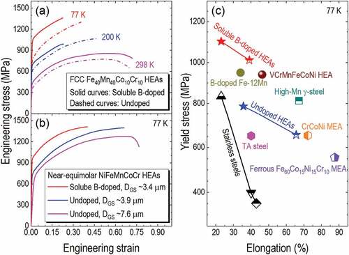
Table 1. Characteristic comparisons of a few typical HEAs (i.e. Al20Li20Mg10Sc20Ti30, low-density refractory CrNbTiVZr, CrMnFeCoNi) and tradictional alloys (see ref. 1 and references therein).
HEA process and laser-cladding
Historically, the advent of HEAs can be traced back to investigation on metallic glass, i.e. amorphous alloys. The same has happened to the methods for processing HEAs. Typically, HEA processes can be grouped into solidus, liquidous and gaseous methods depending on the material state before the as-prepared HEAs[Citation28]. The solidus method includes mechanical alloying followed by sintering, which has the shortcoming of longer time. The gaseous method is typically thin-film deposition from gas source precursors, which is not suitable for large-scale process of thick metallic alloys. In comparison, the liquidus method consists of melting followed by solidification, and the melting process can be realised by electrical arc (either in vacuum or in ambient environment), laser- or electron-beam, or flowing hot-gas. This method dominates amongst the current processes for HEAs. LC is a typical liquidus method that has been widely investigated in processing HEAs, not only for rapidly alloy design and prototyping but also for protective coating, e.g. on structural components of ferrous metals to enhance their corrosion resistance for industrial applications in the areas of oil and gas, marine and offshore, as well as in machinery and systems.
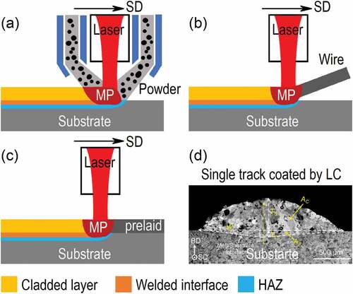
presents typical LC processes that can be used for coating HEA layers on desired substrate using powder feedstock [)], wire feedstock [)] and prelaid layer [). The arrows indicate the scanning direction (SD) of the LC process. Gaseous argon flow can be applied to locally shield the direct laser-heating zone to mitigate potential oxidation and/or nitridation of active elements, e.g. Al and Ti. Generally, an application of wire feedstock, instead of powder feedstock, in LC process can reduce the porosity of coating layers. In comparison, pre-laying of powder feedstock [)] provides a feasible way in obtaining compositional gradient coating, e.g. along the LC direction, which is much more effective than the feeding method [] in accelerating alloy design and prototyping[Citation14]. ) presents a typical cross-sectional image recorded by scanning electron microscopy (SEM) from a single track coating by LC on extrinsic substrate[Citation29]. Substrate dilution of LC process, i.e. mixing of the substrate material into the coating layer, can be derived from the imaged configuration, i.e. the area of the coating layer (AC) and the area of the welded substrate (AP), which is . Different from the configurational measurements, the substrate dilution of LC process can also be evaluated by measuring elemental distribution profiles along the layer building direction across the welded interface between the coating and the substrate[Citation12].
Figure 3. Schematic showing typical laser cladding of metal alloys on metal substrate. (a) Direction deposition using powder feedstock, (b) Direction deposition using wire feedstock and (c) Laser fussion of prelaied powders on substrate. (d) Typical SEM image recorded from the cross-section of cladding path, showing the coating with substrate dilution, i.e. due to the surface melting of the substrate.
LC process of HEA coatings has been extensively developed on various base materials, including Fe-, Ti-, Al-, Mg- and Cu-based metal and alloy substrates, to enhance the surface integrity such as hardness and resistance to corrosion and/or wear. There are a few experimental strategies in designing C coating, they include (1) direct deposition of HEA from feedstock with a few predominant alloying elements while varying one or two elements as additives; (2) using or mitigating substrate dilution in multilayer HEA coatings and (3) coating of ceramic particles reinforced HEA either by introducing ceramic particles into HEA feedstocks for direct deposition or by incorporating precursors into HEA feedstocks followed by in situ synthesis of ceramic particles during LC process.
Direct deposition of HEA coatings by LC
In this method, HEA powder, consisting of a few predominant elements, was mixed at certain composition and particle size distribution. Additional alloying elements were introduced as additives for feedstock engineering to optimise the properties of the HEA coatings. For example, Co2CrNbNi2TiFex (x = 0, 0.5, 1.0 and 2.0) HEA coatings, consisted of FCC and BCC dual-phase solid solutions were deposited by LC on 45-steel substrate[Citation30]. An increase in x increased/decreased the fraction of BCC/FCC, converted the columnar grains to equiaxed, and refined the coarse dendrite structure in HEA coatings. The wear resistance and the hardness of coatings approached their maxima at x = 2.0. The highest hardness of 873.40 HV is three times higher than the 45-steel substrate (i.e. ~200 HV). AlCoCrFeNiMox HEA coatings with x = 0.25, 0.75, 1.0, 1.25 and 1.5 were deposited by LC on 45-steel substrate[Citation31]. The coatings exhibited single phase BCC solid solution at x = 0.75 and 1.0 while Fe- and Mo-rich intermetallic phases emerged at lower (i.e. x = 0.25) and higher (i.e. x = 1.25 and 1.5) Mo contents. The highest hardness of 706 HV was obtained at x = 1.0. Besides, LC deposition of BCoFeNiCrx HEA coatings on 1045-steel substrate with x = 0.5–3.0 exhibited single phase FCC solid solution reinforced by boride particles[Citation32]. The maximum hardness was ~860 HV at x = 0.5. Increased Cr incorporation in the studied range enhanced the oxidation resistance but slightly decreased the hardness of HEA coatings. CoCrFeMnNiAlx HEA coatings were processed by LC on 4Cr5MoSiV steel for oxidation and wear resistance at elevated temperatures[Citation33]. The incorporation of Al refined the grain structure and converted the single-phase FCC solid solution to a mixture of FCC and BCC. Both the grain refinement and the BCC precipitates structurally hardened the coating and enhanced the wear resistance. In addition, rare earth elements have also been studied as additives in HEA coatings by LC. For example, FeMgMoNbTi2Yx HEA coatings were deposited by LC on Q235-steel with x = 0, 0.4, 0.8 and 1.2, respectively[Citation34]. Similar to the effect of Al in CoCrFeMnNiAlx and CoFeNiTiAlx HEA coatings [Citation33,Citation35], the increase in x promoted the emergence of BCC crystals in FCC solid solution. Increased corrosion resistance of the FeMgMoNbTi2Yx HEA coatings occurred at x = 0.8 while the highest hardness of ~1046 HV occurred at x = 1.2. The latter is two times harder than that at x = 0 and five times harder than Q235-steel.
Different from the incorporation of single element additives, two elements were also employed at certain ratios as additives in LC deposition of HEA coatings. For example, Co25Fe25Ni25(BxSi1-x)25 HEAs coatings were deposited by LC on Q235-steel with x = 0.5, 0.6, 0.7 and 0.8, respectively[Citation36]. The effect of B/Si ratios on microstructure of the HEA coatings was studied. At the low B/Si ratios, i.e. x = 0.5 and 0.6, the HEA coating consisted of FCC solid solution, (Fe, Co, Ni)2B compounds and amorphous. When x was increased to 0.7 and 0.8, additional fine precipitates of (Fe, Co, Ni)3B emerged. The hardness increased with B/Si ratios and best wear resistance and high H/E (hardness-to-Young’s modulus) ratio were obtained at x = 0.8, i.e. Co25Fe25Ni25(B0.8Si0.2)25 [Citation36].
Although unintentionally incorporated, ceramic particles such as TiC and Al2O3 have been observed in HEA coatings produced by LC. For example, AlCoCrFeNiTix HEA coatings with x = 0, 0.2, 0.4, 0.6, 0.8 and 1.0 on 1045-steel substrate[Citation37], in which disordered Fe- and Cr-rich BCC and ordered Al- and Ni-rich BCC solid solutions, micro/nano-scale TiC particles and nanoscale Al2O3 particles were observed. Also observed was the incorporation of Ti led to active passivation of HEA coatings, contributed by Al, Ti and Cr, upon chemical corrosion. The best corrosion resistance of HEA coatings was obtained at x = 1.0. Unintentional carbide particles were also found in AlCrFe1.5MoTiWNbx HEA coatings with x = 1.5, 2.0, 2.5 and 3.0 on M2 tool steel[Citation38]. The coating consisted of BCC solid solution, (Nb, Ti)C particles and C14-laves phase. An increase in x to higher than 2.0 converted the cellular crystal structure to columnar. The maximum hardness of 910 HV and the highest wear resistance were obtained at x = 3.0. It is obvious that the carbide and oxide ceramic particles were formed due to contamination, i.e. intrinsic inclusions, of C and O in the feedstock powder.
Substrate dilution and multilayer HEA coatings by LC
Substrate dilution [see )], although can be mitigated, is unavoidable in LC process because of surface melting of substrate to enhance the metallic bond between the coating layer and substrate. This phenomenon has been used in designing Fe-content HEA coating. For example, AlCoCrCuFe HEA coatings were deposited by LC on Q235-steel (i.e. Fe-based) substrate[Citation39]. However, the feedstock solely consisted of Al, Co, Cr and Cu powder, while Fe was intentionally mixed from the Fe-based steel substrate during the LC process. It was found that the coating consisted of single-phase BCC solid solution as a typical dendritic structure grown from the steel substrate. The microhardness of the HEA coating was about three times greater, while the specific wear rate was about an order of magnitude lower than Q235-steel substrate[Citation39].
Substrate dilution-assisted LC deposition of AlCoCrCuFeX0.5 HEA coatings on pure Cu substrate was studied by Wu et al. with X = Si, Mo and Ti, respectively[Citation40]. The feedstock solely consisted of Al, Co, Cr, Fe and X, while the incorporation of Cu was intentionally from the substrate dilution. By optimising the LC processing parameters, crack- and pore-free HEA coatings were obtained on pure Cu substrate. The crystal structure of HEA coatings evolved from dual-phase (i.e. BCC and FCC) solid solutions for X = Si to three-phase structure (i.e. FCC, BCC and intermetallic compounds) for X = Mo and Ti. It was proposed that solidification temperature, instead of melting point, should be considered besides Ω and δ [see )] when designing the solid solution of HEA coatings. The HEA coatings with X = Si exhibited the best corrosion resistance with the corrosion rate two orders of magnitude lower than that of the pure Cu substrate[Citation40].
Al-rich phase structures have been observed along with dual-phase FCC and BCC solid solutions in AlCoCrCuFeNi HEA coatings deposited by LC on pure Al substrate[Citation41]. The Al-rich phase, resulted from substrate dilution, was formed in columnar and equiaxed grain structure. The hardness of coatings was about 550 HV0.2 and the coatings exhibited higher corrosion resistance than Al in 1.0 mol/L H2SO4 solution. The typical corrosion mechanism of HEA coatings was pitting and localised attack. To enhance the corrosion resistance, multilayer coatings with HEA overlay could be deposited by LC. For example, AlCoCrFeNi HEA coatings of multilayer were deposited by LC on Al substrate[Citation42]. The multilayered coatings suppressed the substrate dilution in the overlayer of coating and thus reduced the corrosion resistance of the HEA coatings. AlCoCrCuFeNi HEA coatings were deposited by LC on pure Mg substrate[Citation43]. The coating layer could also be classified into two layers, i.e. a top AlCoCrCuFeNi HEA layer and a bottom composite layer that consisted of partially melted HEA powder (i.e. from the feedstock) in Mg-based matrix. The substrate dilution was mitigated in the top layer. Another interesting finding from this research was that the incorporation of Cu in the HEA feedstock lowered the dilution rate of Mg from the substrate and enhanced the corrosion resistance of HEA coatings[Citation43].
Multilayer AlCoCrCuFeNi HEA coatings have also been deposited by LC on AZ91D Mg-alloy substrate[Citation44]. The coatings consisted of a relatively thick and dense HEA layer of columnar dendrites on top and a thin composite region at the bottom. The average space between the columnar dendrites decreased with the thickness of the coatings, which was attributed to reduced temperature gradient. The morphology did not vary at the remelted boundaries of adjacent cladding paths due to epitaxial growth of metallic crystals. Also found was that columnar-to-equiaxed transition occurred in the top region of multilayer HEA coatings, which was explained in terms of the sluggish diffusion as well as abnormal variation of the temperature-dependent thermal conductivity of HEA coatings.
The pattern-like columnar dendrite structure was also observed in HEA coatings on pure Al substrate. For example, AlCoCrFeNi HEA coatings were deposited by LC on pure Al substrate[Citation45]. The coatings consisted of BCC solid solution in Al-rich matrix along with long range periodic (LRP) structures. The formation of LRP structure was attributed to the laser process, i.e. the characteristics of high temperature and the rapid cooling, which resulted in retention of HEA phase as well as partial decomposition followed by reheating and/or annealing in subsequent paths. The partial decomposition gave rise to precipitates and layered morphology of BCC solid solution with LRP structure[Citation45].
Incorporation of ceramic particles in HEA coatings by LC
WC particles reinforced AlCrCoCuFeNi HEA coatings were deposited by LC on SS316 substrate with WC content of x = 5, 10 and 15 wt.%, respectively[Citation46]. The incorporation of WC particles induced grain refinement and additional phase of WC and Cr23C6 (at x = 10 and 15 wt.%) reinforcement in the FCC and BCC dual-phase solid solutions. Columnar grains were formed in the coating near the interface while nondirectional and equiaxed grains were formed in the regions away from the interface. Both the microhardness, which was increased on increasing x, and the corrosion resistance of the HEA coatings were greater than SS316. However, the corrosion resistance of the HEA coatings decreased with the increase of WC content[Citation46].
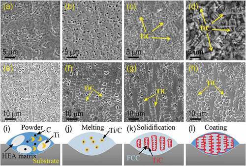
TiC particles have been introduced into AlCoCrCuFe HEA coatings deposited by LC on Q235-steel substrate, the composition of the TiC additive was varied from x = 0 through 10, 30, to 50 wt.%[Citation47]. presents the typical cross-sectional SEM images, showing the microstructural evolution of HEA coating as a function of TiC composition. Dendritic HEA structures and TiC particles could be clearly distinguished at x = 50 wt.% [)]. It was found that the incorporation of TiC increased the hardness of HEA coating. The maximum hardness of 10.82 GPa and excellent wear resistance were obtained at x = 50 wt.%. This hardness is 1.7 times greater than TiC-free, i.e. x = 0, AlCoCrCuFe HEA coating (i.e. 6.29 GPa). Both grain refinement and structural strengthening of TiC particles reinforced AlCoCrCuFe HEA coatings contributed to the increased hardness and wear resistance[Citation47].
Figure 4. Laser cladding of TiC particles reinforced HEA coatings either by incorporating TiC particles into AlCoCrCuFe HEA powder feedstock or by in situ synthesis of TiC particles from elemental Ti and C incorporated in CoCrCuFeNiSi0.2 HEA powder feedstock. (a) AlCoCrCuFe-0TiC, (b) AlCoCrCuFe-10 wt.% TiC, (c) AlCoCrCuFe- 30 wt.% TiC, (d) AlCoCrCuFe-50 wt.% TiC, (e) CoCrCuFeNiSi0.2-(Ti, C)0, (f) CoCrCuFeNiSi0.2-(Ti, C)0.5, (g) CoCrCuFeNiSi0.2-(Ti, C)1.0 and (h) CoCrCuFeNiSi0.2-(Ti, C)1.5. (i)-(l) Schematics showing the in situ synthesis of TiC particles and the TiC particles reinforced dendritic HEA structures within a cladding path. Partly reproduced from Refs. 47 and 50 © 2020 Elsevier.
Y2O3 particles have also been introduced as additives in CoCrCuFeNiSiAl0.5 HEA coatings by LC on H13-steel substrate[Citation48]. Without introducing Y2O3 additive, the coating exhibited dendritic structure with BCC in the dendrite branches and FCC in the inter-dendritic regions. Micro-cracks and pores were found in such HEA coatings. However, on incorporation of Y2O3 particles increased the lattice constant of HEA coatings, refined the grains and, more importantly, eliminated the micro cracks and pores. As a result, hardness and corrosion and wear resistance of HEA coatings were significantly enhanced by incorporating Y2O3 particles.
Jiang et al. deposited CoCrFeMn HEA/TiC/CaF2 self-lubricating coatings by LC on CrCuZr alloy substrate for wear resistance of casting mould[Citation49]. The CoCrFeMn HEA coatings consisted of FCC and HCP solid solutions, which were insoluble in Cu and exhibited a spherical shape driven by surface tension during solidification. In comparison, both CoCrFeMn/TiC and CoCrFeMn/TiC/CaF2 coatings mixed sufficiently with Cu matrix from the substrate. The hardness of the CoCrFeMn/TiC/CaF2 coatings was about twice that of the CoCrFeMn HEA. The incorporation of TiC reduced the friction coefficient and the wear rate of the CoCrFeMn HEA coatings from 0.35 and 3.68 × 10⁻¹⁵ mm3/m to 0.27 and 3.06 × 10⁻¹⁵ mm3/m, respectively. Moreover, the incorporation of CaF2 reduced the friction coefficient and wear rate further to 0.16 and 2.16 × 10⁻¹⁵ mm3/m, respectively. The wear mechanism evolved from abrasive of CoCrFeMn HEA coatings to abrasive and adhesion of the CoCrFeMn/TiC coatings and eventually to adhesion of the CoCrFeMn/TiC/CaF2 coatings[Citation47].
Different from mixing of ceramic particles in HEA feedstock, in situ synthesised ceramic precipitates were also intentionally designed in LC-deposited HEA coatings. For example, by incorporating Ti and C into HEA powder feedstock, TiC particles reinforced CrCoCuFeNiSi0.2, i.e. (CrCoCuFeNiSi0.2)1-x(TiC)x, HEA coatings were obtained by LC on SS304 substrate with TiC content of x = 0, 0.5, 1.0 and 1.5, respectively[Citation50]. Typical microstructural evolution of in situ TiC reinforced HEA coatings are presented in [Citation50]. The coating with x = 0 showed single phase FCC solid solution [see )] and an increase in x in the studied range did not change the phase structure but led to the formation of TiC particles reinforced HEA composites [see ]. The schematic in were proposed to understand the in situ synthesis of TiC particles [] and the TiC-reinforced HEA dendritic structure [] in an individual LC path[Citation50]. The microhardness of 498.5 HV was obtained at x = 1.0, which was much higher than the substrate (~130 HV). Moreover, further increase in x decreased the friction coefficient of TiC particles reinforced CrCoCuFeNiSi0.2 HEA coatings[Citation50].
Similarly, silicide precipitates have been in situ synthesised in near-equimolar AlCrSiTiV HEA coatings processed by LC on Ti-6Al-4 V[Citation51]. The coatings consisted of intermetallic (Ti, V)5Si3 precipitates in BCC matrix, which gave rise to enhanced hardness and wear resistance. The hardness of HEA coatings was 1108 and 628 HV for intermetallic silicide precipitate and BCC matrix, respectively, both are significantly greater than Ti-6Al-4 V substrate (~350 HV). The silicide precipitates also occurred in LC deposition of AlNiSiTiV HEA coatings on Ti-6Al-4 V[Citation52]. The coatings predominately consisted of (Ti, V)5Si3, NiAl-based ordered BCC and TiN phases. The hardness of coatings was as high as 1151∼1357 HV and the wear resistance was about 4–5 times greater than Ti-6Al-4 V substrate at room temperature and 800°C, respectively[Citation52]. Both were attributed to silicide dispersion in BCC solid solution, i.e. forming structural hardening, of HEA coatings. summarises these LC-processed HEA coatings with and without ceramic particles reinforcements, addressing their hardness for protective, especially antiwear, applications.
Table 2. Summary of typical HEA coatings and their characteritics produced by LC on metal and alloy substrates.
Applications of laser-cladded high entropy alloys (LC-HEAs)
As mentioned above, LC is a useful approach for synthesising HEAs with improved surface characteristics beyond casting, magnetron sputtering, plasma arc cladding, electro-spark process, etc., methods[Citation53]. For LC-HEAs, the feedstock materials were continuously deposited and fused in layers on various substrates, forming coatings with the thickness ranging from a few microns to several millimetres[Citation54]. Along with ever-increasing investigations in materials design and technical innovations of HEA, more applications of LC-HEAs are about entering various industrial areas. illustrates the potential fields in which LC-HEAs may be used for antiwear, anticorrosion, antierosion, antioxidation, thermal barrier, hydrogen storage, biomedical, electronics, etc., applications.
Figure 5. Various application areas of LC-HEAs.
Wear, i.e. material lose from the surface due to mechanical interactions, is an important character that may cause functional degradation and failure of structural components. Antiwear is thus an important topic of focus that has long been investigated in metal and metallurgical materials science and engineering. In general, there are three typical wear mechanisms, i.e. abrasive, oxidation and adhesive. Due to the presence of brittle and hard phases as well as the self-lubricating action of the oxidation layer, HEA coatings deposited by LC exhibited excellent wear behaviour at various temperatures. For example, by tailoring the microstructure properties of LC-deposited CoCrCu1-xFeNix HEA coatings, self-lubricated functions can be realised without introducing solid-lubricating agents[Citation55]. This was realised by Cu-segregation into the interdendritic regions that in turn promoted formation of Cu-rich protective oxide layer and thus the enhanced wear resistance at elevated temperatures.
LC-HEA coatings have been explored as self-sealing layers that inhibit the penetration of aqueous solutions and enhance the corrosion resistance for applications in petrochemicals as well as marine and offshore industries[Citation56]. It has been observed that additions of alloying elements to HEA coatings could affect their phase structures and corrosion resistance. Numerous studies have been carried out to examine the impact of elements such as Al, Cr, Co, Nb, Ti and Ni on the corrosion resistance of LC-HEA coatings while taking the effect of substrate dilution into account [Citation57,Citation58].
Cast iron, mild steel and stainless steel are widely used in fabricating high-speed fluid machinery, marine propellers, hydraulic pumps, rudder blades and hydraulic turbine equipment. Surface integrity deteriorations of such components due to slurry erosions tend to degrade the hydraulic efficiency of the turbines. In this regard, erosion-resistant coating plays an important role in this area. HEA coatings have been widely investigated by LC for erosion protections of various steel-based materials. A study on the slurry erosion behaviour of LC-deposited AlxCoCrFeNiTi0.5 HEA coatings with x = 1.0, 1.5, 2.0 and 2.5 by varying the impingement angles from 15 to 90° of 16–40 mesh at 10.08 m/s for different durations revealed a ductile erosion mode at x = 1.0 and a mixed erosion mode (i.e. neither ductile nor brittle) at x = 1.5. In comparison, when x was increased to 2.0 and 2.5, the HEA coatings predominately exhibited brittle erosion mode[Citation58]. The improved erosion properties of the LC-HEA coatings compared with the Q345 steel substrate have been attributed to their high hardness, the good plasticity and the low stacking fault energy.
The oxidation behaviour of LC-HEA coatings has been widely studied in harsh working situations to simulate those of car engines, thermal power plants and nuclear power plants. On the other hand, low-density and high-strength Ti-based alloys, e.g. Ti-6Al-4 V, are recognised as versatile alloy for high-temperature applications, including the petrochemical, power generation and automotive sectors. However, high-temperature oxidations of Ti-based alloys bring out limitations in their applications[Citation59]. Such limitations can be somewhat removed by LC-HEA coatings, e.g. AlCoCrFeNiTi0.5. Oxidation test at 700 and 800°C revealed that the LC-HEA coating has better oxidation resistance than Ti-6Al-4 V. The former was dominated by formation of continuous Al2O3 and Cr2O3 scales while the latter was dominated by for TiO2 scales.
To extend the component life and improve thermal efficiency of gas turbines and jet propulsion systems, thermal barrier coatings (TBCs), often referred to as thermal protective coatings, are routinely applied, especially at the areas directly exposed to high temperatures. A TBC system generally consists of a ceramic topcoat and a bond coat on base material (i.e. the substrate). The bond coat, sandwiched by the ceramic topcoat and the base material, is mainly to increase the coating adherence and, meanwhile, protect the base material from chemical attacks at elevated temperatures, e.g. high-temperature oxidation and hot corrosion that might occur due to the porous characteristic of the ceramic topcoat [Citation60–62]. Xu et al., have compared the high-temperature oxidation behaviours of AlCrCuFeNi HEA bond coat produced by ultrahigh-speed LC and traditional MAlCrY bond coat produced by thermal spray[Citation63]. They found that the AlCrCuFeNi HEA bond coat completed the pre-oxidation, faster than the MAlCrY bond coat, to form a continuous α-Al2O3 thermally grown oxide, which shortened the initial oxidation stage and thereby avoided the formation of other oxides and spinel structures. The sluggish diffusion and the high entropy of the AlCrCuFeNi bond coat gave rise to slow atomic diffusions of Al towards its surface and thus slowed the thickness growth of α-Al2O3 in subsequent isothermal oxidation stages. In other words, both the diffusion- and the oxidation-resistance of the LC produced AlCrCuFeNi HEA bond coat are higher than the thermal sprayed MAlCrY bond coat. Also found was that the consumption of Al from the AlCrCuFeNi HEA bond coat changed its single-phase BCC solid solution to FCC, i.e. maintaining the stable simple solid solution structure [Citation64,Citation65].
LC-HEAs have recently been widely explored in H2 storage applications. H2 is recognised as a clean energy source to replace traditional fossil fuels for mitigating CO2 emissions. However, the safety and cost-efficiency of H2 producing, storage and transportation must be greatly improved for practical routine applications. H2 can be stored in gas-, liquid- and solid-state. Metal/alloy hydride is a typical solid-state storage of H2, which has higher volumetric density of H2 than cylinder gas and cryogenic liquid. The capability of H2 adsorption/desorption, especially at room temperature, is another important specification besides the volumetric density of metal/alloy hydrides for their applications[Citation66]. The unique structural and functional properties of HEAs at room temperature make them promising H2-storage materials. It has been found that the H2-storage capacity of LC-HEAs could be affected by the processing parameters, e.g. the laser power. For example, Kunce et al. have studied a H2-storage system based on laser-deposited equiatomic FeLaMnNiV HEAs[Citation66]. They revealed that the chemical composition and the processing parameter-dependent phase compositions of the FeLaMnNiV HEAs played important roles in their H2-storage properties.
Summary and outlook
We have presented an overview on fundamentals of metal-based HEAs and recent progress in terms of basic design principles, especially the relationship between the element mixing entropy and the phase selection, towards enhanced structural/mechanical properties and chemical/thermal stabilities. Novel properties of HEAs, such as high specific strength and mechanical performance at elevated temperatures and the excellent ductility and fracture toughness at cryogenic temperatures, have been observed in recent years and attributed to the effect of high entropy, severe lattice distortion, sluggish diffusion, as well as the cocktail effect. LC, a typical AM method that has the advantage of being feasible and rapid in designing and prototyping new alloys. This has been extensively investigated while processing HEA coatings on Fe-, Ti, Al-, Mg- and Cu-based metal and alloy substrates for integrity enhancement against plastic deformation, corrosion, wear, oxidation, etc., not only at ambient, but also at elevated, temperatures. The typical design of HEA coatings by LC at the current stage continues to rely on traditional trial-and-error method. By thorough mixing of dominant HEA elements by varying the contents of one or two as additives in the feedstock, the best fit-for-purpose properties of the HEA coatings can be identified by employing optimised LC process. It is important that substrate dilution should be considered in LC process of HEA coatings, from the perspective of elements/composition and structure in the attempt to enhance the coating performance. Ceramic particles can be appropriately mixed in the feedstock and can also be in situ synthesised from the precursor stock in the HEA feedstock, to reinforce the HEA matrix for performance enhancement of the protective coating by LC. Based on promising findings and recent achievements in automation, machine learning and artificial intelligence, we believe that more HEAs coatings with better enhanced properties can be discovered by LC for advanced protective applications.
Acknowledgments
The authors from IMRE acknowledge support from A*STAR RIE2020 advanced manufacturing and engineering (AME) programmatic grant through the structural metal alloys program (SMAP, Grant no. A18B1b0061, Project no. SC25/18-8R1715-PRJ6). Dura-Metal (S) Private Limited is acknowledged for technical advice.
Disclosure statement
No potential conflict of interest was reported by the author(s).
Additional information
Funding
References
- Ye YF, Wang Q, Lu J, et al. High-entropy alloy: challenges and prospects. Mater Today. 2016;19(6):349–14.
- Yeh J-W, Chen S-K, Lin S-J, et al. Nanostructured high-entropy alloys with multiple principal elements: novel alloy design concepts and outcomes. Adv Eng Mater. 2004;6(5):299–303.
- Cantor B, Chang ITH, Knight P, et al. Microstructural development in equiatomic multicomponent alloys. Mater Sci Eng A. 2004;375-377:213–218.
- Kaushik N, Meena A, Mali HS. High entropy alloy synthesis, characterisation, manufacturing & potential applications: a review. Mater Manuf Processes. 2022;37(10):1085–1109.
- Lim WYS, Cao J, Suwardi A, et al. Recent advances in laser-cladding of metal alloys for protective coating and additive manufacturing. J Adhesi Sci Technol. 2022;1–23. 10.1080/01694243.2022.2085499
- Huang Y, Hu Y, Zhang M, et al. Multi-objective optimization of process parameters in laser cladding CoCrCuFeNi high-entropy alloy coating. J Therm Spray Technol. 2022;31(6):1985–2000.
- Liu H, Tan CKI, Cheng WS, et al. Effects of robotic hammer peening on structural properties of ni-based single-crystal superalloy: dislocation slip traces and crystallographic reorientations. Metall Mater Trans A. 2020;51(6):3180–3193.
- Liu H, Ivan Tan CK, Wei Y, et al. Robotic hammer peening-induced martensite in austenitic steels: spatial distributions of plastic deformation and phase transformation. Procedia CIRP. 2020;87:297–301.
- Liu H, Meng TL, Cao J, et al. Comparisons on localized surface modifications of stainless steels induced by laser shock peening and robotic hammer peening. Procedia CIRP. 2022;108:118–122.
- Liu H, Meng TL, Cao J et al Advanced surface engineering and protective coating Wei, Yuefan, Shng, Shuyun. Lecture Notes in Mechanical Engineering. Singapore: Springer Singapore; 2022. p. 138–141. doi:10.1007/978-981-16-5763-4_30.
- Liu H, Tan CKI, Dong X , et al. Laser-cladding and robotic hammer peening of stainless steel 431 on low alloy steel 4140 for surface enhancement and corrosion protections. J Adhesi Sci Technol. 2022;36(21):2313–2327.
- Liu H, Tan CKI, Wei Y, et al. Laser-cladding and interface evolutions of inconel 625 alloy on low alloy steel substrate upon heat and chemical treatments. Surf Coat Technol. 2020;404:126607.
- Liu H, Tan CKI, Meng TL, et al. Hot corrosion and internal spallation of laser-cladded inconel 625 superalloy coatings in molten sulfate salts. Corros Sci. 2021;193:109869.
- Sova A, Doubenskaia M, Trofimov E, et al. Deposition of high-entropy alloy coating by cold spray combined with laser melting: feasibility tests. J Therm Spray Technol. 2022;31(4):1112–1128.
- Liu H, Tan CKI, Meng TL, et al. Direct deposition of low-cost carbon fiber reinforced stainless steel composites by twin-wire arc spray. J Mater Process Technol. 2022;301:117440.
- Yang X, Zhang Y. Prediction of high-entropy stabilized solid-solution in multi-component alloys. Mater Chem Phys. 2012;132(2–3):233–238.
- Ye YF, Wang Q, Lu J, et al. The generalized thermodynamic rule for phase selection in multicomponent alloys. Intermetallics. 2015;59:75–80.
- Tsai KY, Tsai MH, Yeh JW. Sluggish diffusion in Co–Cr–Fe–Mn–Ni high-entropy alloys. Acta Materialia. 2013;61(13):4887–4897.
- Yeh J-W. Alloy design strategies and future trends in high-entropy alloys. JOM. 2013;65(12):1759–1771.
- Senkov ON, Senkova SV, Woodward C, et al. Low-density, refractory multi-principal element alloys of the Cr–Nb–Ti–V–Zr system: microstructure and phase analysis. Acta Materialia. 2013;61(5):1545–1557.
- Stepanov ND, Shaysultanov DG, Salishchev GA, et al. Structure and mechanical properties of a light-weight alnbtiv high entropy alloy. Mater Lett. 2015;142:153–155.
- Youssef KM, Zaddach AJ, Niu C, et al. A Novel low-density, high-hardness, high-entropy alloy with close-packed single-phase nanocrystalline structures. MaterRes Lett. 2015;3(2):95–99
- Yurchenko N, Panina E, Zherebtsov S, et al. Oxidation behaviour of eutectic refractory high-entropy alloys at 800–1000 °C. Corros Sci. 2022;205:110464.
- Wang M, Ma ZL, Xu ZQ, et al. Designing Vxnbmota refractory high-entropy alloys with improved properties for high-temperature applications. Scr Mater. 2021;191:131–136.
- Moschetti M, Burr PA, Obbard E, et al. Design considerations for high entropy alloys in advanced nuclear applications. J Nucl Mater. 2022;567:153814.
- Gludovatz B, Hohenwarter A, Catoor D, et al. A fracture-resistant high-entropy alloy for cryogenic applications. Science. 2014;345(6201):1153–1158.
- Seol JB, Bae JW, Kim JG, et al. Short-range order strengthening in boron-doped high-entropy alloys for cryogenic applications. Acta Materialia. 2020;194:366–377.
- Zhang W, Liaw PK, Zhang Y. Science and technology in high-entropy alloys. Sci China Mater. 2018;61(1):2–22.
- Chao Q, Guo T, Jarvis T, et al. Direct laser deposition cladding of AlxCoCrFeNi high entropy alloys on a high-temperature stainless steel. Surf Coat Technol. 2017;332:440–451.
- Zhang Y, Han T, Xiao M, et al. Tribological behavior of diamond reinforced FeNiCoCrTi0.5 carbonized high-entropy alloy coating. Surf Coat Technol. 2020;401:126233.
- Juan YF, Li J, Jiang YQ, et al. Modified criterions for phase prediction in the multi-component laser-clad coatings and investigations into microstructural evolution/wear resistance of FeCrCoNiAlMox laser-clad coatings. Appl Surf Sci. 2019;465:700–714.
- Chang F, Cai B, Zhang C, et al. Thermal stability and oxidation resistance of FeCrxCoNiB high-entropy alloys coatings by laser cladding. Surf Coat Technol. 2019;359:132–140.
- Cui Y, Shen J, Manladan SM, et al. Wear resistance of FeCoCrNiMnAlx high-entropy alloy coatings at high temperature. Appl Surf Sci. 2020;512:145736.
- Gu Z, Mao P, Gou Y, et al. Microstructure and properties of MgMoNbFeTi2Yx high entropy alloy coatings by laser cladding. Surf Coat Technol. 2020;402:126303.
- Sun Z, Zhang M, Wang G, et al. Wear and corrosion resistance analysis of FeCoNiTiAlx high-entropy alloy coatings prepared by laser cladding. Coatings. 2021;11(2):155.
- Cheng J, Sun B, Ge Y, et al. Effect of B/Si Ratio on structure and properties of high-entropy glassy Fe25Co25Ni25(BxSi1-X)25 coating prepared by laser cladding. Surf Coat Technol. 2020;402:126320.
- Liu J, Liu H, Chen P, et al. Microstructural characterization and corrosion behaviour of AlCoCrFeNiTix high-entropy alloy coatings fabricated by laser cladding. Surf Coat Technol. 2019;361:63–74.
- Wang H, Liu Q, Guo Y, et al. MoFe1.5CrTiWAlNbx refractory high-entropy alloy coating fabricated by laser cladding. Intermetallics. 2019;115:106613.
- Zhang S, Wu CL, Yi JZ, et al. Synthesis and characterization of FeCoCrAlCu high-entropy alloy coating by laser surface alloying. Surf Coat Technol. 2015;262:64–69.
- Wu CL, Zhang S, Zhang CH, et al. Phase evolution characteristics and corrosion behavior of FeCoCrAlCu-X0.5 coatings on Cp Cu by laser high-entropy alloying. Opt Laser Technol. 2017;94:68–71.
- Shi Y, Ni C, Liu J, et al. Microstructure and properties of laser clad high-entropy alloy coating on aluminium. Mater Sci Technol. 2018;34(10):1239–1245.
- Shon Y, Joshi SS, Katakam S, et al. Laser additive synthesis of high entropy alloy coating on aluminum: corrosion behavior. Mater Lett. 2015;142:122–125.
- Yue TM, Xie H, Lin X, et al. Solidification behaviour in laser cladding of AlCoCrCuFeNi high-entropy alloy on magnesium substrates. J Alloys Compd. 2014;587:588–593.
- Meng GH, Protasova NA, Kruglov EP, et al. Solidification behavior and morphological evolution in laser surface forming of AlCoCrCuFeNi multi-layer high-entropy alloy coatings on Az91d. J Alloys Compd. 2019;772:994–1002.
- Katakam S, Joshi SS, Mridha S, et al. Laser assisted high entropy alloy coating on aluminum: microstructural evolution. J Appl Phys. 2014;116(10):104906.
- Vyas A, Menghani J, Natu H. Influence of Wc particle on the metallurgical, mechanical, and corrosion behavior of AlFeCuCrCoNi-WCx high-entropy alloy coatings. J Mater Eng Perform. 2021;30(4):2449–2461.
- Jiang PF, Zhang CH, Zhang S, et al. Fabrication and wear behavior of tic reinforced FeCoCrAlCu-based high entropy alloy coatings by laser surface alloying. Mater Chem Phys. 2020;255:123571.
- Liu J, Guan Y, Xia X, et al. Laser cladding of Al0.5CoCrCuFeNiSi high entropy alloy coating without and with yttria addition on H13 steel. Crystals. 2020;10(4):320.
- Jiang J, Li R, Yuan T, et al. Microstructural evolution and wear performance of the high-entropy FeMnCoCr Alloy/TiC/CaF2 Self-lubricating composite coatings on copper prepared by laser cladding for continuous casting mold. J Mater Res. 2019;34(10):1714–1725.
- Guo Y, Li C, Zeng M, et al. In-Situ TiC reinforced CoCrCuFeNiSi0.2 high-entropy alloy coatings designed for enhanced wear performance by laser cladding. Mater Chem Phys. 2020;242:122522.
- Huang C, Zhang Y, Vilar R, et al. Dry sliding wear behavior of laser clad TiVCrAlSi high entropy alloy coatings on Ti–6Al–4V substrate. Mater Des. 2012;41:338–343.
- Zhang HX, Dai JJ, Sun CX, et al. Microstructure and wear resistance of TiAlNiSiV high-entropy laser cladding coating on Ti-6Al-4V. J Mater Process Technol. 2020;282:116671.
- Zhong M, Liu W. Laser surface cladding: the state of the art and challenges. Proc Inst Mech Eng C J Mech Eng Sci. 2010;224(5):1041–1060
- Shi T, Shi J, Xia Z, et al. Precise control of variable-height laser metal deposition using a height memory strategy. J Manuf Process. 2020:57, 222–32.
- Ostovari Moghaddam A, Samodurova MN, Pashkeev K, et al. Evgeny A.Trofimov, A novel intermediate temperature self-lubricating CoCrCu1-xFeNix high entropy alloy fabricated by direct laser cladding. Tribol Int. 2021;156:106857.
- Alaneme KK, Bodunrin MO, Oke SR. Processing, alloy composition and phase transition effect on the mechanical and corrosion properties of high entropy alloys: a review. J Mater Res Technol. 2016;5(4):384–393.
- Ullah Arif Z, Yasir Khalid M, Ur Rehman E, et al. A review on laser cladding of high-entropy alloys, their recent trends and potential applications. J Manuf Processes. 2021;68:225–273.
- Zhao J, Ma A, Ji X, et al. Slurry erosion behavior of AlxCoCrFeNiTi0.5 high-entropy alloy coatings fabricated by laser cladding. Metals. 2018;8(2):126–132.
- Cui W, Li W, Chen W-T, et al. Laser metal deposition of an AlCoCrFeNiTi0.5 high-entropy alloy coating on a Ti6Al4V substrate: microstructure and oxidation behavior. Crystals. 2020;10(8):638–645.
- Ghadami F, Aghdam A, Rouh S, et al. Microstructural characteristics and oxidation behavior of the modified MCrAlX coatings: a critical review. Vacuum. 2021;185:109980.
- Chen H, Fan M, Zhu W, et al. High temperature oxidation behaviour of combustion flame sprayed CoNiCrAlY coatings. Surf Coat Technol. 2020;385:125431.
- Ghadami F, Aghdam A, Ghadami S. A comprehensive study on the microstructure evolution and oxidation resistance of conventional and nanocrystalline MCrAlY coatings. Sci Rep. 2021;11(1):1–21.
- Q-L X, Zhang Y, Liu S-H, et al. High-temperature oxidation behavior of CuAlNiCrFe high-entropy alloy bond coats deposited using high-speed laser cladding process. Surf Coat Technol. 2020;398, 126093.
- Liu X, Wang T, Li C, et al. Microstructural evolution and growth kinetics of thermally grown oxides in plasma sprayed thermal barrier coatings. Prog Nat Sci Mater Int. 2016;26(1):103–111.
- Saremi M, Afrasiabi A, Kobayashi A. Microstructural analysis of YSZ and YSZ/ Al2O3 plasma sprayed thermal barrier coatings after high temperature oxidation. Surf Coat Technol. 2008;202(14):3233–3238.
- Kunce I, Pola´nski M, Czujko T. Microstructures and hydrogen storage properties of LaNiFeVMn alloys. Int J Hydrogen Energy. 2017;42(44):27154–27164.