
ABSTRACT
A Ti3C2 MXene/Ti composite powder was developed through surface modification and powder coating for producing a high-performance titanium matrix composites (TMCs) by laser power bed fusion. Introducing MXene rarely changed the original sphericity and flowability of Ti powder while it slightly enhanced the laser absorption capacity of Ti powder. The printing conditions in turn affected the morphology and distribution of MXene in as-printed composites. At optimised printing parameters, majority of MXene with high structural integrity and uniform distribution remained along the grain boundaries of as-printed composites, and a combination of high surface quality, geometrical accuracy and densification was obtained. The remaining MXene played the synergy of pulling-out effect and load transfer role, which increased the yield strength from 530 to 710 MPa, while retaining good ductility (elongation of 19.8%). Compared with ASTM standard cast Ti64 alloy, our MXene/Ti composites also exhibited superior comprehensive tensile properties and excellent strength-ductility synergy.
Introduction
Titanium matrix composites (TMCs) have superior mechanical performance, such as higher specific strength, stiffness and modulus compared with the corresponding Ti alloy matrix because of introduction of reinforcement [Citation1–5]. This enables TMCs to be gradually applied in aerospace and military fields [Citation6–8]. Given the increasing demand of industry, high-performance TMCs with superior mechanical properties and multiple functions are urgently required [Citation9]. Morphology and distribution characteristics of reinforcements are decisive factors in determining their strengthening mechanism and improvement effect on mechanical properties [Citation10–14]. According to the morphology and size, the category of reinforcement can be roughly classified into particles [Citation15], whiskers (short fibres) [Citation16], nanotubes [Citation17] and two-dimensional (2D) nanosheets [Citation18–20]. Particles and whiskers are commonly distributed along grain boundaries (GBs) and play a specific pinning role in enhancing the mechanical properties of the Ti matrix, especially for high-temperature strength [Citation2,Citation15]. The increase in strength is highly dependent on the volume fraction of particles and whiskers [Citation21]. In order to obtain required tensile properties, Zhang et al. [Citation21] introduced greater than 5 vol.% hybrid (TiC particles and TiB whiskers) into the Ti matrix. Although an increase of ~200 MPa in yield strength was obtained, the elongation was decreased to less than 3% because of the negative effect of massive reinforcement on ductility.
As compared with particles and whiskers, nanotubes and nanosheets commonly exhibit higher strengthening efficiency resulting from their good interfacial bonding and effective load-transferring from the Ti matrix to reinforcements [Citation22–24]. Wang et al. [Citation25] prepared a type of carbon nanotubes (CNTs)-strengthened TMCs through spark plasma sintering (SPS) at low temperature. A considerable strengthening efficiency of ~36.8 was achieved at a small expense of ductility by introducing 0.4 wt.% CNTs in the Ti matrix, confirming the excellent strengthening role. Similarly, Mu et al. [Citation24] developed a locally aligned graphene nanosheets-strengthened TMCs using SPS at low temperature followed by hot-rolling. ~280% increase in compressive yield strength was obtained by adding 0.8 wt.% graphene, suggesting a remarkable strengthening effect. Additionally, they revealed that the strengthening efficiency of graphene can be significantly enhanced by reducing the stacking-layer number of graphene. Given the nature of carbon materials, CNTs and graphene possess high-temperature reactivity with Ti matrix to form interfacial TiC products. The massive and coarse GB-distributed TiC significantly lowers their strengthening efficiency and deteriorates the ductility [Citation26]. In such a case, TMCs strengthened by CNTs and graphene nanosheets required to be produced by SPS under limited sintering conditions (low temperature and short dwelling time) to alleviate the reaction degree. However, this neither completely eliminated the formation of interfacial reaction products, nor achieved a high densification for as-sintered parts. Furthermore, the remaining high reactivity of carbon reinforcement in as-sintered component continues to be a potential safety hazard in high-temperature service condition [Citation27]. Thus, developing new reinforcement candidates that simultaneously possess the strengthening behaviour similar to nanotubes and nanosheets and excellent high-temperature reactive inertia with the Ti matrix is required for the design and preparation of a novel high-performance TMCs.
Ti3C2 MXene is an emerging two-dimensional nanosheet that has numerous advantages, such as high stiffness and specific strength, as well as considerable thermal and electrical conductivity [Citation28,Citation29]. Moreover, the high-temperature reactivity of MXene with the Ti matrix is much lower that of graphene because it is essentially a type of Ti carbide. In this sense, employing Ti3C2 MXene, instead of graphene, is promising in not only remaining more 2D nanosheet reinforcements through reducing interfacial reaction in TMCs, but also enhancing the transfer load efficiency of remained nanosheets. Heretofore, MXene has been used in electrochemical energy storage field [Citation30], but it was rarely employed as reinforcement in metal matrix composites. In our previous work, a few-layered Ti3C2 MXene-coated Ti64 composite powder was developed via powder surface modification using fluidisation technology [Citation31]. MXene nanosheets were completely remained in the Ti matrix after sintering and enhanced the compressive yield strength, demonstrating the high-temperature reactive inertia of MXene with Ti and effective strengthening effect. However, the unique 2D structure and uniform dispersion characteristics of few-layered MXene rendered a complete coverage on powder surface. This produced a natural barrier that prevented high-temperature diffusion between the Ti powder of MXene nanosheets, thereby deteriorating the sintering densification. Meanwhile, the limited forming accuracy of powder sintering technology and the increased difficulty in processing resulted from the presence of MXene reinforcement also restricted the production of complex components and the application in key engineering fields.
Given that the powder surface modification can obtain uniform MXene-coating on Ti powder without significantly changing the original shape and contour of powder, we were inspired to coat uniform MXene nanosheets on spherical Ti powder and produce MXene-strengthened TMCs through laser power bed fusion (LPBF, a type of 3D printing). On the one hand, the isolation effect of MXene nanosheets on diffusion can be eliminated because powder experiences melting and solidification process so as to obtain a high density. On the other hand, the unique manufacturing characteristics of LPBF (local powder melting, layer-by-layer building manner and ultrafast heating/cooling rates) has potential to circumvent the segregation and structural damage problems of MXene in high-temperature Ti melt and enables us to achieve large retention and high dispersion uniformity of MXene nanosheets in as-printed samples [Citation32–34]. In addition, LPBF is an enabling technology providing a design freedom that offers the possibility of producing desirable shapes and thereby solves the manufacturing problem of complex parts for MXene-strengthened TMCs [Citation35].
In this study, a uniform MXene-coated Ti (MXene/Ti) composite powder was fabricated by surface functional modification of MXene followed by solid-liquid fluidised bed technology for the ultimate sake of producing a novel TMCs with good combination of strength and ductility through LPBF. This present study focuses on the following aspects: (i) tuning mechanism of MXene-coating for synthesising a high-quality composite powder suitable for LPBF, (ii) interaction behaviour between composite powder and laser beam, and relationship between forming quality of printed parts and printing parameters, (iii) variation in phase constitute and distribution characteristics of reinforcements on tuning printing parameters, and (iv) strengthening behaviour and mechanism of obtained reinforcements in as-printed composite.
Materials and methods
Preparation of MXene/Ti composite powder
Gas-atomised spherical Ti powder (15–53 μm, Nonferrous Metals Holding Group Co., Ltd) and Ti3C2Tx MXene flake (−400 mesh, Guangzhou Foshan Xinxi Technology Co., Ltd., Tx = – O, – OH and – F hydrophilic functionalization) were used as starting materials. The MXene flake was dispersed in dimethyl sulphoxide (DMSO) for intercalation. Subsequently, the as-treated MXene was dispersed in deionised water and sonicated for 1 h to obtain MXene solution. Then, cetyl trimethyl ammonium bromide (CTAB) was added in the solution and mixed thoroughly to obtain modified MXene with electropositivity. 50 g of Ti powder was added into a solid-liquid fluidised bed reactor filled with modified MXene solution (300 ml) to make MXene/Ti composite powder. The liquid flow velocity, the concentration of MXene in solution and fluidisation time were selected as variables to tune the quality, distribution characteristics and coating-content of MXene in composite powder. After the coating treatment, the obtained powder was put into a gas-solid fluidised bed reactor for removal of pre-introduced functional groups in as-treated MXene under a flowing argon of 500 sccm. The reduction temperature and time were 750°C and 30 min, respectively.
LPBF of MXene/Ti composite powder
The obtained MXene/Ti composite powder was printed into parts by LPBF (AFS-M120, Longyuan AFS Co., Ltd). The fixed parameters were laser spot size (D) of 75 μm, layer thickness (t) of 30 μm, and hatch spacing (h) of 100 μm. The laser power (P) and scanning speed (v) were selected as variables to obtain suitable printing parameters for the MXene/Ti composite powder, thereby achieving high-quality and high-performance printed composite parts. The laser energy density was controlled by tuning P and v, according to the equation of laser power density (E), which is defined as a function of LPBF processing parameters of E = P/vth [Citation36]. Cuboidal parts of dimensions 10 mm × 10 mm × 5 mm were built for studying the manufacturing quality and densification behaviour of composite powder under different parameters and the microstructural characterisation. Dog bone-shaped specimens (width of 6 mm, thickness of 3 mm and gage length of 25 mm) were printed for tensile testing.
Characterisation and tensile testing
Morphology of as-received and modified MXene nanosheets, composite powder and as-printed samples were studied by scanning electron microscopy (SEM, JEOL JSM-7001 F) and transmission electron microscopy (TEM, JEOL JEM-2100Plus). SEM samples were polished using standard metallography technique followed by etching in Kroll’s reagent for 60s. TEM samples of as-modified MXene were prepared by ultrasonic dispersion followed by collection on a Cu grid. TEM sample for the analysis of reinforcement in as-printed samples were prepared by ion milling. A zeta potential analyser (DelsaNano C) was employed to study the electrical properties of MXene before and after surface functional modification and Ti powder in aqueous solution. Tensile experiments were conducted at a strain rate of 6.67 × 10⁻⁴ s−1 using a universal testing machine (WDW-20). The fracture surface of tensile samples was observed by SEM (JEOL JSM-7001 F). Tensile test for each condition was repeated three times to obtain average values and ensure good accuracy.
Results and discussion
Morphology, dispersion and tuning mechanism of MXene/Ti composite powder
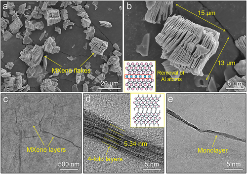
shows the morphology of as-received Ti3C2Tx MXene flakes, which exhibited similar size and appeared as stack of paper. gives a closer view of a typical MXene flake with the size of ~ 13 μm in width and 15 μm in thickness. The inset illustrates the structural sketch of Ti3AlC2 MAX phase, indicating that the unique structure and morphology of MXene flake was derived from selectively etching Al atoms in MAX phase. Thus, the flake comprised alternative MXene nanosheets and interval gaps because of the extraction of Al atoms. However, the MXene nanosheets retained the flake form rather than monodisperse MXene nanosheets. Thus, the intercalator was applied on MXene flake in solution for delamination and the obtained products were examined by TEM. As shown in , the as-treated MXene exhibited thin membrane-like morphology, indicating a good delamination effect. Higher magnification view clearly shows the cross-sectional morphology of delaminated MXene nanosheets, and few-layered and monolayered MXene nanosheets were observed in , respectively. Additionally, schematic diagram (inset of ) indicated that each MXene nanosheet comprised three layers of Ti atoms and two layers of C atoms, and Tx functionalization existed on the surface of each MXene nanosheet. This was consistent with the observation of MXene nanosheets in .
Figure 1. (a) SEM image of as-received Ti3C2Tx MXene flakes, (b) high-magnification SEM image of a typical MXene flake and its preparation mechanism, (c) a bright-field (BF) TEM image showing the surface morphology of as-treated MXene, (d) and (e) BF TEM images showing the cross-sectional morphologies of few-layered and monolayered MXene nanosheets, respectively.
The zeta electrical potential of pristine Ti powder and delaminated MXene in aqueous solution were measured to be −22.7 and −27.2 mV, respectively. The electronegative homogeneity caused a problem that Ti powder and MXene nanosheets were mutually exclusive in aqueous solution and thereby inhibited the uniform coating of MXene on Ti powder surface. In such a case, electropositive CATB was employed to conduct surface functional modification on delaminated MXene in solution. The measured zeta electrical potential of CTAB-modified MXene was +41.8 mV, indicating successful electrical transition. The electro-negative to -positive transition was promising for overcoming the exclusive effect between Ti powder and MXene, and thus providing a feasible route to make uniform MXene/Ti composite powder.
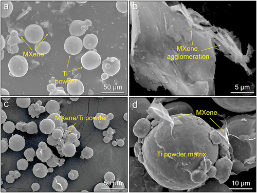
shows the morphology and mixing effect of powder mixture prepared from pristine Ti powder and the modified MXene nanosheets. It is seen that MXene nanosheets were self-agglomerated and detached from Ti powder surface. A higher magnification SEM image of agglomerated MXene nanosheets is shown in . The delaminated MXene were agglomerated into a flake, while interval gaps between nanosheets disappeared, suggesting that the agglomeration resulted from the external force during the mixing process. It was reported that delaminated MXene nanosheets had strong sheet-to-sheet van der Waals interactions and easily tend to agglomerate [Citation37]. Meanwhile, the collision force from grinding balls and surrounding Ti powders also aggravated the agglomeration of MXene nanosheets during mixing. As a consequence, it was inferred that the uniform dispersion of MXene nanosheets on Ti powder surface was hardly achieved by traditional powder mixing route, even though the electrical properties of MXene and Ti powder was tuned to be opposite. show the dispersion effect of MXene nanosheets in Ti powder using solid-liquid fluidised bed. No obvious self-agglomeration phenomenon was observed, and vast majority of MXene nanosheets were absorbed on the surface of powder (). The closer view of a typical powder shows that MXene nanosheets were uniformly coated on powder and exhibited thin membrane-like morphology (). This indicated that the van der Waals force between MXene nanosheets was successfully overcome through dispersing CTAB-modified MXene and Ti powder by solid-liquid fluidised bed. The underlying mechanism is described as follows: CATB-modified MXene nanosheets dispersed well in the aqueous solution because of hydrophilic functionalization. The flow force of liquid overcame the agglomeration characteristics of MXene nanosheets, and the distinct electrical properties significantly improved the absorption capability of CATB-modified MXene nanosheets to Ti powder. Meanwhile, the flowing solution with homogeneous MXene nanosheets carried Ti powder to perform reciprocating motion in solid-liquid fluidised bed. This unique mobile behaviour of fluidised powder further enhanced the dispersion uniformity of MXene coating on Ti powder [Citation31].
Figure 2. (a) and (b) SEM images of powder mixture prepared from pristine Ti powder and the CTAB-modified MXene nanosheets by ball-milling, (c) and (d) SEM images of CTAB-modified MXene-coated Ti powder prepared by solid-liquid fluidised bed.
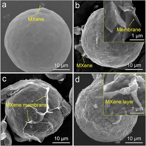
Based on the feasibility verification of producing MXene/Ti composite powder, establishing a tuning mechanism of MXene coating is of importance to obtain a high-quality MXene/Ti composite powder. The MXene concentration in solution and the flow velocity of liquid in fluidised bed are considered as key factors affecting the quality of MXene/Ti composite powder. shows the morphology of composite powder fabricated at different MXene concentration. At low MXene concentration (0.1 wt.%), few MXene nanosheets were attached on Ti powder surface (). On increasing the MXene concentration from 0.1 to 0.3 wt.%, the coating amount of MXene was increased significantly and the edges of MXene nanosheets were distinguishable (inset of ). On further increasing the concentration to 0.5 wt.%, the vast majority of powder surface was covered by MXene nanosheets, indicative of ultrahigh coverage (). Meanwhile, the shape of powder was not changed significantly, dominating that the presence of MXene coating did not destroy the original sphericity of Ti powder. This was important for the subsequent feed process of LPBF. However, on increasing the MXene concentration to 1.0 wt.%, the thickness and layer numbers of local MXene coating were increased significantly (). This indicated that an excessive MXene concentration led to the localised overlap of MXene nanosheets on powder surface, which was detrimental to the uniformity of MXene nanosheets in composite powder. Hence, the MXene concentration of 0.5 wt.% was selected to make high-quality composite powder with high uniformity and less layer number of MXene nanosheets.
Figure 3. SEM images of MXene/Ti composite powder fabricated by fluidised bed at different MXene concentrations: (a) 0.1 wt.%, (b) 0.3 wt.%, (c) 0.5 wt.% and (d) 1.0 wt.%.
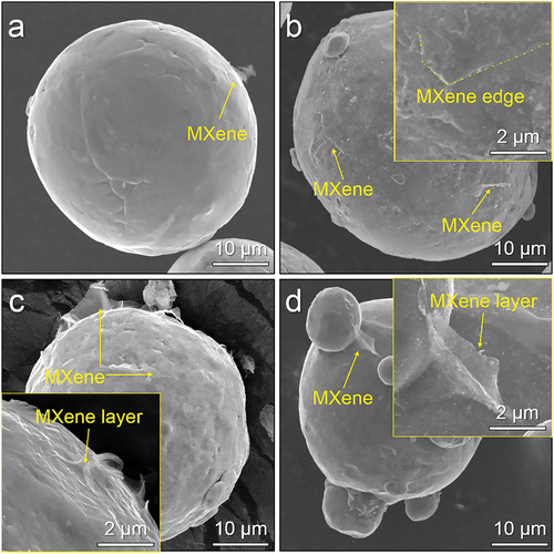
The flow velocity of MXene solution in fluidised bed is another important factor that influences the dispersion condition of MXene nanosheets on Ti powder surface. shows the morphological variation of powder as a function of flow velocity under a fixed MXene concentration of 0.5 wt.%. As shown in , few MXene nanosheets were observed on powder surface because of excessive high flow velocity, suggesting that the absorption capability of MXene to Ti powder was smaller than the exfoliation effect derived from the solution with high flow velocity. On decreasing the flow velocity from 5 to 3 sccm, membrane-like MXene nanosheets were covered on the powder surface (). The edges of MXene nanosheets were distinguishable, indicative of an ultrathin thickness. It may be noted that some regions of powder surface did not have MXene coating, indicating that the flow velocity was still too high for obtaining uniform MXene/Ti composite powder. Thus, the flow velocity was decreased to 1 sccm. A larger amount of MXene nanosheets were distributed uniformly on powder and no agglomeration phenomenon was observed (). The majority of powder surface was covered by MXene with ultrathin thickness, indicating that the flow velocity of 1 sccm was suitable for making high-quality MXene/Ti composite powder. On further decreasing the flow velocity from 1 to 0.5 sccm, although the powder surface was also uniformly coated by MXene nanosheets, some satellite powder was attached on the powder with larger size (). This indicated that insufficient flow velocity possibly led to the absorption of small powder to large powder because of the bonding effect from MXene nanosheets (inset of ). As a consequence, the parameters for preparation of MXene/Ti composite powder were optimised to be the MXene concentration of 0.5 wt.% in solution and the flow velocity of 1 sccm in solid-liquid fluidised bed.
Figure 4. SEM images of MXene/Ti composite powder fabricated by solid-liquid fluidised bed under a fixed MXene concentration of 0.5 wt.% but using different flow velocity: (a) 5sccm, (b) 3 sccm, (c) 1 sccm and (d) 0.5sccm.
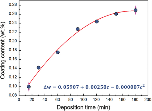
depicts the variation of MXene-content in composite powder as a function of fluidisation time. The content increased significantly on prolonging the fluidisation time during the initial stage of coating. However, the increasing rate decreased gradually with the fluidisation time and the increase of MXene-content in composite powder rarely varied when the fluidisation time exceeded 120 min. This phenomenon was attributed to the fact that the surface of Ti powder was gradually covered by electropositive MXene nanosheets on increasing the MXene-content, such that the as-coated powder exhibited electrical homogeneity with the CTAB-modified MXene in solution. This inhibited the continuous coating of MXene on as-coated Ti powder. From these measurements and using a least-square approach, the MXene-content in composite powder as a function of fluidisation time approximately followed a parabolic law (see the equation in ). The correlation coefficient (R2) was 0.9878, indicative of high fitting quality. When the fluidisation time was controlled at 120 min, the MXene-content reached ~0.25 wt.% in composite powder at the optimised parameters. On further increase of fluidisation time, the variation in MXene-content was negligible. It should be mentioned that the higher MXene-content in composite powder could be probably improved by increasing the MXene concentration in solution, but it was detrimental to the dispersion uniformity of MXene in composite powder. As a consequence, the MXene/Ti composite powder produced at optimised parameters (MXene concentration of 0.5 wt.%, flow velocity of 1 sccm and fluidisation time of 120 min) was selected for the following research.
Figure 5. Variation of MXene-content in composite powder as a function of fluidisation time.
Thermal reduction treatment was conducted on the composite powder in gas-solid fluidised bed at 750°C for 30 min to remove contaminations, and the morphology of reduced composite powder is shown in . The majority of powder surface remained to be coated by uniform and thin MXene nanosheets, indicating that the thermal reduction rarely destroyed the MXene-coating. High sphericity and flowability are important evaluation indices of printability for MXene/Ti composite powder and key factors that influence the forming quality and mechanical performance of as-printed parts [Citation38]. The measured flowability values of pristine Ti powder and the optimised MXene/Ti composite powder were 27.1 s/50 g and 27.3 s/50 g, respectively. This indicated that uniformly coating thin MXene nanosheets on Ti powder rarely affected the original flowability and the subsequent feeding behaviour of composite powder during LPBF process.
Figure 6. (a) SEM image of the thermal-reduced MXene/Ti composite powder, and (b) laser reflectivity of pristine Ti powder and the MXene/Ti composite powder.
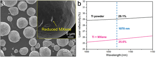
compares the difference in the laser reflectivity between pristine Ti powder and the MXene/Ti composite powder. At the selected laser wavelength of 1070 nm for LPBF in this work, the laser reflectivity of powder was slightly decreased from 29.1% to 25.6% by introducing MXene nanosheets, indicative of an enhanced laser absorption capacity of powder. This can affect the interaction between powder and laser beam, thereby modifying the densification behaviour during solidification process. This means that the commercial printing conditions and previously reported printing parameters could not be suitable for manufacturing the MXene/Ti composite powder. Thus, it is of importance to study the printing response of the composite powder and optimise parameters for printing TMCs with high forming quality and good mechanical performance.
Printing response and as-printed microstructure of MXene/Ti composite powder
shows the photographs of as-printed cubes from MXene/Ti composite powder under different printing parameters. The numbering of samples and their corresponding printing parameters are listed in . Although the composite powder was successfully processed into cubes at all the selected conditions, the forming quality of as-printed samples was varied on changing laser power and scanning speed. At relatively low scanning speed (500 and 750 mm/s) combined with high laser power (250 and 300 W), the surface quality and geometrical accuracy of samples (S2 to S5 and S7 to S10) were poor, exhibiting an apparent over-melting and surface collapse phenomena. This was attributed to the excessive laser energy density and improved laser absorption capability of Ti powder by coating MXene nanosheets. In contrast, the surface quality and geometrical accuracy of samples became higher on either increasing scanning speed or lowering laser power, indicating an acceptable forming quality can be obtained using these printing parameters.
Figure 7. (a) Photographs of as-printed cubes of MXene/Ti composite powder under different parameters, and (b) the relative density of the as-printed cubes.
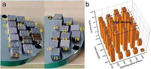
Table 1. Numbering of as-printed samples under different printing parameters.
High densification is another prerequisite for producing certified TMCs components from the MXene/Ti composite powder using LPBF. illustrates the relative density of as-printed MXene/Ti composites under different parameters. The relative density of samples was lower than ~94% of theoretical density when printing the composite powder at low laser power (100 W) and high scanning speed (1500 mm/s). This was ascribed to the existence of unmelted powder and metallurgy defects resulted from insufficient laser energy input into powder. However, too high a laser energy density, such as the laser power of 300 W combined with scanning speed of 500 mm/s, also hardly obtained high printed density because excessive energy input led to the volatilisation of Ti melt and resultant small pores in as-printed samples. Consequently, to obtain a synergy of high densification (relative density of greater than 99%) and good forming quality, the laser power and scanning speed should be controlled in the range of 150 to 250 W and 750 to 1250 mm/s, respectively.
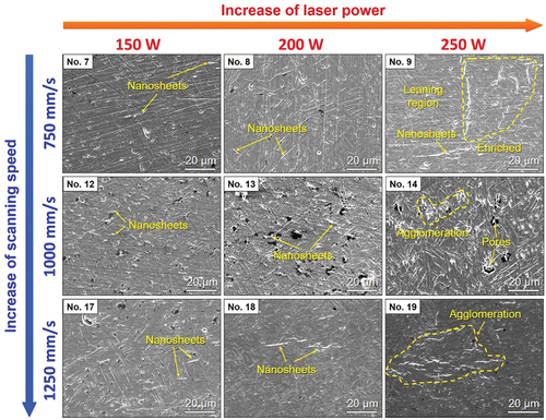
displays SEM images of samples printed from MXene/Ti composite powder, showing the microstructural evolution with change in printing conditions. No unmelted powder and less pores were observed for samples, indicating high density obtained under the given parameter tuning range. This was consistent with the density measurement results (). Furthermore, nanosheet-like phase were present in all of the samples, and the amount was increased on increasing in the scanning speed. The increase of scanning speed decreased the interaction time between MXene-coating and laser, thereby reducing the detrimental effect of high-energy laser on the retention of MXene nanosheets in as-printed samples. Regarding the effect of laser power on the as-printed microstructure, the densification rarely changed while the distribution uniformity of nanosheets was decreased on increasing the laser power. In particular, obvious agglomeration of nanosheets was observed for the samples printed at 250 W. This phenomenon was attributed to the fact that higher laser power interacting with composite powder accelerated the powder melting and increased the residence time of MXene in the Ti melt. In such a case, more MXene nanosheets floated on the surface of melt because of the significant surface tension and difference in density between MXene and melt [Citation39]. This in turn facilitated the agglomeration of MXene and caused inhomogeneous distribution of MXene in the solidified Ti matrix. Consequently, it was inferred that the retention amount of MXene nanosheets was dependent on scanning speed, while the distribution characteristics was highly related to laser power.
Figure 8. SEM images of samples printed from MXene/Ti composite powder, showing the as-printed microstructure at different printing conditions.
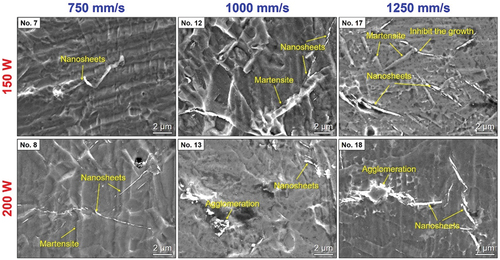
shows high-magnification SEM images of as-printed samples from MXene/Ti composite powder, showing the influence of printing conditions on the morphology and distribution characteristics of MXene nanosheets in the Ti matrix and their reverse effect on solidified microstructure. MXene nanosheets were successfully remained in all of the samples, confirming the high-temperature stability. Furthermore, on increasing the laser energy density (lowering scanning speed and increasing laser power), the agglomeration phenomenon and broken debris of MXene nanosheets were gradually observed by comparing samples S8 and S17. In addition, some MXene nanosheets were distributed in vicinity of martensite, indicating that the presence of remained MXene inhibited the growth of martensite and provided a refinement effect.
Figure 9. High-magnification SEM images of as-printed samples, showing morphology and distribution of remained MXene nanosheets and their effect on the Ti matrix.
To study the high-temperature stability of MXene and the influence of laser energy density on the retention behaviour of MXene, TEM was performed on as-printed samples S8 (200 W and 750 mm/s) and S17 (150 W and 1250 mm/s). As shown in , MXene nanosheets with ultrathin thickness remained and distributed along GBs of sample S8, which was consistent with the SEM observation (). Meanwhile, some platelet-like microstructure was observed inside the α-Ti grains (). According to the corresponding dark-field (DF) TEM image using the (2 − 1 1 2) spot of diffraction patterns (), the platelet-like microstructure was determined to be dislocations rather than the widely reported intragranular Ti8C5 precipitates in previous Refs. [Citation40–42]. Furthermore, the DF TEM observation also confirmed that the remained nanosheets were mainly distributed along the GBs. In the case of sample S17 printed under lower laser energy density, numerous nanosheets were observed along the GBs, indicating that increasing laser density did not change the distribution characteristics (). A higher magnification TEM image of sample S17 is shown in ; some needle-like phases with the size of ~200 nm in length and ~20 nm in width were observed and determined as martensite, which was widely reported in Ti alloys fabricated by LPBF [Citation36,Citation43,Citation44,]. As consistent with the SEM observation (), the MXene nanosheets were located at the tip region of the martensite. This indicated that the presence of MXene nanosheets inhibited the growth of martensite during solidification process. The secondary phase in samples S8 and S17 was extracted on Cu grid through replica method for further studying the morphology and distribution dependence of reinforcement on laser energy density. As shown in , typical membrane-like nanosheets and some broken debris were observed in sample S8. According to the diffraction patterns, both of them were identified to be Ti3C2 MXene. It was thus inferred that partial MXene coatings on Ti powder surface that directly interacted with laser were physically broken into debris because of high laser energy input. Nevertheless, the broken MXene debris retained the original crystal structure and did not evolve into other compounds. In contrast, the vast majority of MXene retained 2D membrane-like morphology and structural integrity in sample S17 that was printed at the lower laser energy density (). Meanwhile, rare broken MXene debris and contaminations were detected, confirming the excellent high-temperature and chemical stability of MXene. In a brief summary, the laser energy density can influence the morphology and distribution uniformity of MXene in as-printed samples. At relatively high laser energy density, agglomeration and physical broken debris of MXene nanosheets appeared because of stronger interaction between laser and composite powder and prolonged residence time of MXene in Ti melt. However, the MXene nanosheets only experienced physical damage rather than structural damage because of unique stability [Citation45]. This enabled us to retain the physicochemical property and strengthening role of MXene in as-printed samples on the premise of high densification through tuning the printing parameters.
Figure 10. TEM studies of samples (a-c) S8 and (d-f) S17: (a, d, e) BF TEM images showing the morphology and distribution of remained MXene and the as-printed microstructure, (b) the corresponding DF TEM image of (a), (c) and (f) the morphology of extracted secondary phase from as-printed samples, and the insets in (c) and (f) are corresponding diffraction patterns and the composition of extracted phase, respectively.
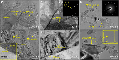
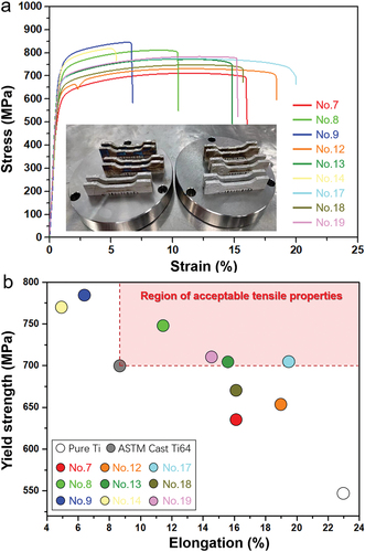
Figure 11. (a) Tensile stress‒strain curves of as-printed MXene/Ti composites under different parameters, and (b) comparison of tensile properties among our printed composites with as-printed pure Ti sample and the ASTM standard cast Ti64 alloy.
Tensile properties and fracture behaviour of as-printed MXene/Ti composites
shows the tensile stress‒strain curves of as-printed MXene/Ti composites at different conditions (the as-printed tensile samples are shown in the inset of ). Although the samples exhibited distinct tensile properties, all of them experienced yield stage, indicating that the existence of MXene did not caused abnormal fracture of samples. Compared with other samples, S8 exhibited the highest ultimate tensile strength (UTS, 851 MPa) and yield strength (YS, 775 MPa). In contrast, S17 possessed relatively good YS (710 MPa) and remained a superior tensile elongation (EL, 19.8%), indicating a good strength-ductility synergy. depicts the YS and EL values of present samples, the ASTM standard cast Ti64 alloy and as-printed pure Ti part processed under optimal printing conditions (laser power of 300 W and scanning speed of 1000 mm/s) [Citation33]. All of as-printed MXene/Ti composites exhibited a significantly superior YS compared with the pure Ti sample (530 MPa), confirming the strengthening effect of MXene on the Ti matrix. Meanwhile, samples S12 and S17 remained good ductility in a manner similar to that of pure Ti sample, indicative of good comprehensive tensile properties. ASTM standard is commonly used to evaluate the mechanical properties of engineering materials and the feasibility of industrial practice. As compared with the ASTM standard cast Ti64 alloy (YS of 698 MPa and elongation of 9%) [Citation46], our samples S8, S13, S17 and S19 exhibited superior comprehensive tensile properties. The strength and ductility synergy is the prerequisite and key basis for structural materials applied in engineering practice [Citation47–49].
Strengthening behaviour and mechanism of MXene in as-printed composites
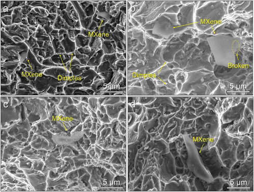
shows the fracture surface of our printed composites that exhibited superior tensile properties compared with ASTM standard cast Ti64 alloy. Retained MXene nanosheets were observed in all the samples, confirming the strengthening role of MXene. The fracture microstructure of sample S8 comprised torn and equiaxed dimples, indicating that the existence of martensite also contributed to the increase of YS (). In the case of sample S13, the amount of torn dimples was decreased and some MXene nanosheets with larger superficial area were observed in . This confirmed that increasing the scanning speed reduced the formation amount of martensite and alleviated the damage of MXene nanosheets. Both of them were beneficial for the increase of ductility. Meanwhile, some broken MXene nanosheets were observed in the vicinity of dimples (). This indicated that the MXene nanosheets acted as the major bearing subjects and experienced a serious distortion during the tensile deformation, verifying the effective loading transfer effect of MXene nanosheets from the Ti matrix. show the fracture surface of samples (S17 and S19) with higher ductility. Both of them mainly consisted of smaller equiaxed dimples and MXene nanosheets, and the thickness of MXene nanosheets in sample S17 was smaller compared with the sample S13. This was mainly attributed to the increased scanning speed and the reduced amount of martensite, which accounted for higher ductility of sample S17 compared with S13 and S8.
Figure 12. SEM images of fracture surface of as-printed samples: (a) S8, (b) S13, (c) S17 and (d) S19.
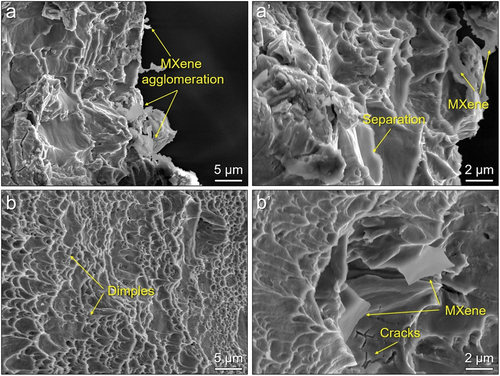
shows the cross-sectional SEM fractograph of samples S8 and S17. Cracks were observed on the Ti matrix of sample S8, and some broken MXene debris were present on the fracture surface (). Based on the TEM observations (), the broken MXene debris was originated from the MXene coating rather than the tensile deformation. In such a case, the pre-formed MXene debris and martensite preferentially acted as crack initiation sites, leading to the occurrence of localised cracking and resultant decrease in ductility (). In comparison, the cross-sectional fractograph of sample S17 was mainly composed with smaller equiaxed dimples (). As shown from the closer view (), unbroken MXene were present in the vicinity of the dimples. This suggested that the MXene nanosheets also played a significant pulling-out effect and bearing capability on suppressing the propagation of cracks. As a consequence, the remained MXene nanosheets are capable of enhancing the tensile strength of as-printed sample through the synergy of pulling-out effect and the load transfer from the Ti matrix. This enabled the sample S17 to significantly improve the tensile strength without largely sacrificing ductility. Although the MXene nanosheets in S8 were broken into debris that led to the significant decrease in the loading transfer effect, they also provided a dispersion strengthening effect on improving the tensile strength. Additionally, the presence of massive martensite also enhanced the strength. In such a case, the sample S8 exhibited the superior tensile strength compared with sample S17 but at a large expense of ductility.
Figure 13. Cross-sectional SEM fractograph of samples: (a and a’) S8 and (b and b’) S17.
Conclusions
In this study, an MXene-coated Ti composite powder for LPBF of high-performance TMCs was developed through surface functional modification of Ti3C2 MXene followed by fluidised bed technology. The tuning mechanism of MXene/Ti composite powder based on the fluidisation parameters, the printing response of composite powder, the dependence of as-printed microstructure and reinforcements on printing conditions, and the strengthening behaviour and mechanism of remained MXene in as-printed composites were studied and discussed in detail. Main conclusions are summarised below.
The morphology and distribution of MXene coating in composite powder were dependent on fluidisation parameters. At optimised parameters (MXene concentration of 0.5 wt.% in aqueous solution, flow velocity of 1 sccm and fluidisation time of 120 min), A uniform MXene/Ti composite powder was obtained with the MXene-content of 0.25 wt.%. The obtained composite powder retained high sphericity and flowability that were similar to pristine Ti powder. The presence of MXene-coating slightly reduced the laser reflectivity of Ti powder and enhanced the laser absorption capacity of powder.
A synergy of high densification and good forming quality was obtained at the following printing condition ranges (laser power of 150 to 250 W combined with scanning speed of 750 to 1250 mm/s). The high-temperature stability of MXene enabled them to be retained in as-printed samples under printing conditions mentioned above. Excessive laser power caused the agglomeration of MXene nanosheets, and too slow a scanning speed physically broke the MXene into debris but rarely destroyed the crystal structure. At the optimised printing condition (laser power of 150 W and scanning speed of 1250 mm/s), vast majority of MXene with original 2D membrane-like morphology and high structural integrity remained and uniformly distributed along the GBs of as-printed sample.
Under the optimised printing conditions, the introduction of MXene significantly increased the tensile strength of Ti matrix without large sacrifice in ductility. The remaining MXene played the synergy of pulling-out effect and load transfer from the Ti matrix. Compared with ASTM standard cast Ti64 alloy, the optimal samples exhibited superior comprehensive tensile property, suggesting a good application potential in industrial practice.
CRediT authorship contribution statement
L. Wang: Investigation, Data Curation, Writing – original draft, Formal analysis, Methodology, Writing – review & editing. J. Li: Methodology, Writing – review & editing, Formal analysis. Z.Q. Liu: Investigation, Writing – original draft, Formal analysis, Writing – review & editing. S.F. Li: Conceptualization, Writing – review & editing, Supervision, Funding acquisition. Y.F. Yang: Writing – review & editing and Supervision, Funding acquisition. R.D.K. Misra: Writing – review & editing. Z.J. Tian: Writing – review & editing and Supervision.
Acknowledgments
The research study was supported by the National Natural Science Foundation of China (Nos. 52174349 and 52074254), the Project of Key Laboratory of Science and Technology on Particle Materials (No. CXJJ-22S043), Chinese Academy of Sciences, and the Provincial Key Research and Development Program (BE2019002).
Disclosure statement
The authors declare that they have no known competing financial interests or personal relationships that could have appeared to influence the work reported in this paper.
Additional information
Funding
References
- Hayatb MD, Singh H, He Z, et al. Titanium metal matrix composites: an overview. Compos Part A Appl Sci Manuf. 2019;121:418–16.
- Huang LJ, An Q, Geng L, et al. Multiscale architecture and superior high-temperature performance of discontinuously reinforced titanium matrix composites. Adv Mater. 2020;33(6):2000688.
- Munir KS, Li YC, Qian M, et al. Identifying and understanding the effect of milling energy on the synthesis of carbon nanotubes reinforced titanium metal matrix composites. Carbon. 2016;99:384–397.
- Li GX, Munir K, Wen C, et al. Machinablility of titanium matrix composites (TMC) reinforced with multiwalled carbon nanotubes. J Manuf Processes. 2020;56:131–146.
- Wang S, Huang LJ, Zhang R, et al. Enhancing ductility of titanium matrix composites by multimodal α-grains. Scr Mater. 2019;170:161–165.
- Dong LL, Lu JW, Fu YQ, et al. Carbonaceous nanomaterial reinforced Ti-6Al-4V matrix composites: properties, interfacial structures and strengthening mechanisms. Carbon. 2020;164:272–286.
- Williams JC, Starke EA. Progress in structural materials for aerospace systems. Acta Materialia. 2003;51(19):5775–5779.
- Wang S, An Q, Zhang R, et al. Microstructure characteristics and enhanced properties of network-structured TiB/(TA15-Si) composites via rolling deformation at different temperatures. Mater Sci Eng A. 2022;829:142176.
- Yan Q, Chen B, Cao L, et al. Improved mechanical properties in titanium matrix composites reinforced with quasi-continuously networked graphene nanosheets and in-situ formed carbides. J Mater Sci Technol. 2022;96:85–93.
- Li Z, Zhang Y, Zhang Z, et al. A nanodispersion-in-nanograins strategy for ultra-strong, ductile and stable metal nanocomposites. Nat Commun. 2022;13(1):5581.
- Huang LJ, Geng L, Peng H-X. Microstructurally inhomogeneous composites: is a homogeneous reinforcement distribution optimal? Pro Mater Sci. 2015;71:93–168.
- Li SF, Cui JY, Yang LF, et al. In situ growth of carbon nanotubes on Ti powder for strengthening of Ti matrix composite via nanotube-particle dual morphology. Metall Mater Trans A. 2020;51(11):5932–5944.
- Zhang R, Huang LJ, Zhao XX, et al. Influence of deformation parameters and network structure to the microstructure evolution and flow stress of TiBw/Ti64 composite. Mater Sci Eng A. 2021;809:140997.
- Munir KS, Li Y, Liang D, et al. Effect of dispersion method on the deterioration, interfacial interactions and re-agglomeration of carbon nanotubes in titanium metal matrix composites. Mater Des. 2015;88:138–148.
- Hayat MD, Singh H, Miodowski A, et al. Fabrication, microstructure and mechanical properties of in situ formed particle reinforced titanium matrix composite. Int J Refract Metals Hard Mater. 2020;92:105257.
- Liu Y, Dong LL, Lu JW, et al. Microstructure and mechanical properties of SiC nanowires reinforced titanium matrix composites. J Alloys Compd. 2020;819:152953.
- Munir KS, Kingshott P, Wen C. Carbon nanotube reinforced titanium metal matrix composites prepared by powder metallurgy—a review. Critl Rev Solid State Mater Sci. 2015;40(1):38–55.
- Yan Q, Chen B, Zhang B, et al. Inhibiting the interfacial reaction between few-layered graphene and titanium via SiC nanoparticle decoration. J Alloys Compd. 2022;893:162183.
- Zhang FM, Wang J, Liu TF, et al. Enhanced mechanical properties of few-layer graphene reinforced titanium alloy matrix nanocomposites with a network architecture. Mater Des. 2020;186:108330.
- Cao HC, Liang YL. The microstructures and mechanical properties of graphene-reinforced titanium matrix composites. J Alloys Compd. 2020;812:152057.
- Zhang CJ, Kong FT, Xiao SL, et al. Evolution of microstructure and tensile properties of in situ titanium matrix composites with volume fraction of (TiB + TiC) reinforcements. Mater Sci Eng A. 2012;548:152–160.
- Dong LL, Zhang W, Fu YQ, et al. Synergetic enhancement of strength and ductility for titanium-based composites reinforced with nickel metallized multi-walled carbon nanotubes. Carbon. 2021;184:583–595.
- Mu XN, Cai HN, Zhang HM, et al. Uniform dispersion and interface analysis of nickel coated graphene nanoflakes/pure titanium matrix composites. Carbon. 2018;137:146–155.
- Mu XN, Cai HN, Zhang HM, et al. Uniform dispersion of multi-layer graphene reinforced pure titanium matrix composites via flake powder metallurgy. Mater Sci Eng A. 2018;725:541–548.
- Wang FC, Zhang ZH, Sun YJ, et al. Rapid and low temperature spark plasma sintering synthesis of novel carbon nanotube reinforced titanium matrix composites. Carbon. 2015;95:396–407.
- Misra RDK. Strong and ductile texture-free ultrafine-grained magnesium alloy via three-axial forging. Mater Lett. 2023;331:133443.
- Kondoh K, Threrujirapapong T, Umeda J, et al. High-temperature properties of extruded titanium composites fabricated from carbon nanotubes coated titanium powder by spark plasma sintering and hot extrusion. Compos Sci Technol. 2012;72(11):1291–1297.
- Li YX, Huang SH, Wei CJ, et al. Adhesion of two-dimensional titanium carbides (MXenes) and graphene to silicon. Nat Commun. 2019;10(1):3014.
- Ji B, Fan SW, Ma X, et al. Electromagnetic shielding behavior of heat-treated Ti3C2Tx MXene accompanied by structural and phase changes. Carbon. 2020;165:150–162.
- Xia Y, Mathis TS, Zhao MQ, et al. Thickness-independent capacitance of vertically aligned liquid-crystalline MXenes. Nature. 2018;557(7705):409–412.
- Wang L, Liu ZQ, Li SF, et al. Few-layered Ti3C2 MXene-coated Ti–6Al–4V composite powder for high-performance Ti matrix composite. Compos Commun. 2022;33:101238.
- Li HL, Yang ZH, Cai DL, et al. Microstructure evolution and mechanical properties of selective laser melted bulk-form titanium matrix nanocomposites with minor B4C additions. Mater Des. 2020;185:108245.
- Liu Y, Li SF, Misra RDK, et al. Planting carbon nanotubes within Ti-6Al-4V to make high-quality composite powders for 3D printing high-performance Ti-6Al-4V matrix composites. Scr Mater. 2020;183:6–11.
- Dong YP, Li YL, Ebel T, et al. Cost-affordable, high-performance Ti–TiB composite for selective laser melting additive manufacturing. J Mater Res. 2020;35(15):1922–1935.
- Zhu Y, Zhang K, Meng Z, et al. Ultrastrong nanotwinned titanium alloys through additive manufacturing. Nat Mater. 2022;21(11):1258–1262.
- Xu W, Brandt M, Sun S, et al. Additive manufacturing of strong and ductile Ti–6Al–4V by selective laser melting via in situ martensite decomposition. Acta Materialia. 2015;85:74–84.
- Zhou WW, Zhou ZX, Fan YC, et al. Significant strengthening effect in few-layered MXene-reinforced Al matrix composites. Mater Res Lett. 2021;9(3):148–154.
- Herzog D, Seyda V, Wycisk E, et al. Additive manufacturing of metals. Acta Materialia. 2016;117:371–392.
- Arkhurst BM, Bae JH, Na MY, et al. Effect of tellurium on the microstructure and mechanical properties of Fe-14Cr oxide-dispersion-strengthened steels produced by additive manufacturing. J Mater Sci Technol. 2021;95:114–126.
- Li SF, Yang YF, Misra RDK, et al. Interfacial/intragranular reinforcement of titanium-matrix composites produced by a novel process involving core-shell structured powder. Carbon. 2020;164:378–390.
- Li SF, Tan C, Liu Y, et al. Designing core-shell C-coated Ti-6Al-4V powders for high-performance nano-sized TiC platelets/particles synergistically reinforced Ti-6Al-4V composites. Materialia. 2018;2:68–72.
- Luo SD, Li Q, Tian J, et al. Self-assembled, aligned TiC nanoplatelet-reinforced titanium composites with outstanding compressive properties. Scr Mater. 2013;69(1):29–32.
- Ren YM, Lin X, Fu X, et al. Microstructure and deformation behavior of Ti-6Al-4V alloy by high-power laser solid forming. Acta Materialia. 2017;132:82–95.
- Zhang TL, Huang ZH, Yang T, et al. In situ design of advanced titanium alloy with concentration modulations by additive manufacturing. Science. 2021;374(6566):478–482.
- Wozniak J, Jastrzębska A, Olszyna A. Challenges and opportunities in tailoring MAX phases as a starting materials for MXenes development. Mater Technol Adv Perform Mater. 2022;37(11):1639–1650.
- ASTM International. ASTM F1108-14, Standard Specification for Titanium-6Aluminum-4Vanadium Alloy Castings for Surgical Implants (UNS R56406). West Conshohocken PA: ASTM International; 2014.
- Misra RDK, Challa VSA, Injeti VSY. Phase reversion-induced nanostructured austenitic alloys: an overview. Mater Technol Adv Perform Mater. 2022;37(7):437–449.
- Yang YF, Geng K, Li SF, et al. Highly ductile hypereutectic Al-Si alloys fabricated by selective laser melting. J Mater Sci Technol. 2022;110:84–95.
- Chen GX, Zhai Q, Ma ZH, et al. Effect of Cr content on microstructure, mechanical properties and corrosion behavior of Ti6Al4V alloy produced by selective laser melting. Mater Technol Adv Perform Mater. 2022;37(9):1062–1074.