
ABSTRACT
Magnetic and magneto-optical studies were carried out in microwires that had been subjected to the bending annealing. A previously unobserved effect of bending-annealing-induced magnetic bistability was discovered. This effect is observed only in the region of the sample subjected to bending. The length of the longitudinal region of the sample, in which the effect of induced bistability takes place, depended on the bending radius. In contrast to the classical version of this effect, bending-induced bistability was accompanied by the rapid movement of the longitudinal domain wall in the microwire surface.
Introduction
Magnetic amorphous microwires are of interest for research from two points of view. Firstly, it is a widely used active element in magnetic sensors [Citation1–3]. On the other hand, they are of interest from the point of view of fundamental research [Citation4–6].
As for the technical application of microwires, there are several magneto-electrical effects, which serve as a base for the microwire-based magnetic sensors. The most used effect is the Giant Magneto Impedance Effect (GMI) [Citation7–9]. In addition, such effect as Matteucci effect also has a promising future in sensory application [Citation10,Citation11]. The fundamental interest is determined by the great variety of different types of magnetic structures, domain configurations, and transitions between them observed in microwires and nanowires [Citation12,Citation13].
In soft magnetic materials with cylindrical symmetry, the magnetization can be oriented along the long wire axis. Therefore, amorphous wires can present peculiar magnetic properties, like so-called magnetic bistability characterized by perfectly rectangular hysteresis loops [Citation14–18]. This property has found its technical application and continues to be in demand [Citation19,Citation20].
The origin of the magnetic bistability of amorphous glass-coated microwires is usually attributed to the fast magnetization switching of a single large axially magnetized domain [Citation18]. The onset of this peculiar domain structure, consisting of a large axially magnetized single domain and an outer radially magnetized shell, is determined by the stresses arising during the simultaneous rapid solidification of the composite wire, consisting of a metallic nucleus surrounded by the glass coating [Citation18].
It is also worth mentioning the effect of circular magnetic bistability observed in microwires, which is similar in nature to the effect of axial magnetic bistability [Citation21]. This effect was observed using magneto-optical technique. When an electric current flows through a microwire, inducing a circular magnetic field, a Barkhausen jump occurs at the surface of the sample.
For most of aforementioned properties (GMI, Matteucci effects) the magnetic softness is essentially relevant [Citation2,Citation7,Citation9]. The magnetic softness of amorphous wires is associated with their amorphous structure, characterized by the absence of the defect characteristic of crystalline materials [Citation2]. Accordingly, in amorphous microwires, the magnetic softness is mainly affected by the magnetoelastic anisotropy and, hence, the magnetostriction coefficient, λs, values and sign and the internal stresses related to fabrication process are essentially relevant [Citation2].
In the case of glass-coated microwires (studied in this work) the main source of the internal stresses is originated by the different thermal expansion coefficients of a metallic alloy and glass coating [Citation2,Citation4]. Although such internal stresses are rather complex, the largest component has an axial orientation [Citation2,Citation4].
On the other hand, the λs signs and values are mostly affected by the chemical composition of amorphous alloys. Thus, a high and positive λs are observed for Fe-rich microwires, while low and negative λs-values are reported for Co-rich alloys microwires [Citation2]. Therefore, an axial magnetic anisotropy is observed in Fe-rich microwires, while a circumferential magnetic anisotropy and almost linear hysteresis loops have been observed in Ço-rich amorphous microwires [Citation2].
In this work, we had a special interest in the study of magnetic wires subjected to the effect of bending [Citation11,Citation14]. This interest was not accidental. There is a special scientific field devoted to magnetic structures subjected to various types of bending stress [Citation22–26]. We considered that, given the obvious lack of experimental results in this area, flexible glass-covered microwires, which we have previously extensively studied, are very suitable objects for this kind of research.
As for the actual motivation for the presented study, these were the recent investigation studies of GMI and Matteucci effects in bended microwires [Citation11,Citation27]. It has become clear to us that the application of the mechanical bending of magnetic wires opens up new horizons in the technical use of magnetic microwires. On the other hand, mechanical bending showed a new channel for influencing the magnetic structure in order to modify it.
Also, the presented studies can be considered within the framework of the idea of studying the magnetic properties distributed along the length of a long sample. Previously, such a distribution was caused by annealing at temperatures distributed along the microwire length [Citation28]. Now, we are expanding this direction by adding external influence such as bending stress distributed along the length of the microwire. The main feature of this type of research is the smooth change from point-to-point in the physical properties of the sample, which provides a wider opportunity to analyse the physical processes occurring in the sample.
The original idea implemented in the presented studies is that after bending annealing and subsequent straightening of the sample, the magnetic structure of the microwire retaining the properties induced by the bending.
Experiment
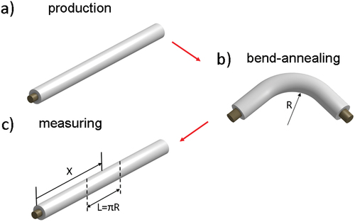
We studied two glass-coated microwires with chemical composition of Fe71.7B13.4Si11Nb3Ni0.9 (diameter of metallic nucleus d = 103 μm, total diameter with glass covering D = 158 μm) prepared by Taylor-Ulitovsky technique. The manufactured samples had a uniform distribution of magnetic properties along the microwire length. Then, the microwire was subjected to the following annealing procedure schematically presented in . After the manufacture, the samples were bended and annealed in the bended state (Tann = 300°C (45 min)). The annealing was carried out in air because insulating and continuous glass coatings protect microwires against oxidation. The radius R () of the bending was 2 cm for the sample 1 and 1 cm for the sample 2. Then, the samples were unbent and examined in the straightened state.
Figure 1. Schematic picture of the samples preparation for the measuring.
The hysteresis loops were obtained using the fluxmetric method, previously used for characterization of magnetically soft microwires and described in details [Citation29].
When the magnetic flux changes over time, an electromotive force proportional to this change is induced in the circuit. The fluxmetric measurement set-up consists of the primary exciting system to generate the magnetic field and the secondary pick-up coil. Once an alternating magnetic field is applied at a fixed frequency provided by the power supply, the change in the magnetization of the sample is detected by the pick-up coil. The induced in the pick-up coil signal, proportional to the magnetization of the sample, is integrated by the fluxmeter.
A thin (about 8 mm of diameter) 12-cm-long solenoid creates a rather uniform axial magnetic field in the region where a sample of 10 cm long is inserted. The fluxmetric method allows the measurement of hysteresis loops up to H = 3 kA/m. A short (2 mm long) pick-up coil was used to characterize the bending-annealed microwires, which can show hysteresis loops with different shape for different regions of the microwire. Such setup allowed us to measure the hysteresis loops in different longitudinal regions of the microwire by moving the short pick-up coil along it.
The magneto-optical Kerr effect (MOKE) technique has been applied as a method to acquire the contrast images of the surface magnetic domain structures [Citation30]. The experiments were performed by means of a high-resolution, wide-field, optical polarizing microscope based on a commercial one (Carl Zeiss) working in reflective mode using the longitudinal MOKE configuration [Citation30].
Experimental results
The experimental results are presented in (fluxmetric loops) and (MOKE images of the surface domain structure). demonstrates the fluxmetric hysteresis loops obtained in the samples 1 () and sample 2 (). The coloured lines are corresponding to the hysteresis loops obtained at different distance X from the end of the sample (X is shown in ). The loops marked as X = 50 mm were measured at a point corresponding to the middle of the sample. ) demonstrate all hysteresis loops, obtained during the fluxmetric experiments. ) demonstrate the hysteresis loops corresponding to the central part of the samples 1 and 2. It is necessary to note that the length L (see ) was equal 6.28 cm for the case of the sample 1 and was equal 3.14 cm for the case of the sample 2.
Figure 2. Fluxmetric hysteresis loops obtained in the samples 1 () and sample 2 (). ) demonstrate the hysteresis loops corresponding to the central part of the samples 1 and 2. shows the hysteresis loops obtained in high magnetic field (sample 1) in points corresponding to X=10 mm and 50 mm. shows the hysteresis loops obtained in samples 1 and 2 in points corresponding to X=50 mm.
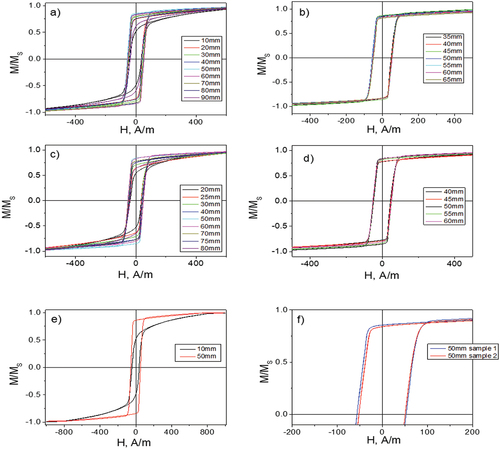
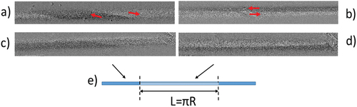
Figure 3. Images of the surface magnetic structure corresponding to different parts of the sample 1 (a, b) and sample 2 (c, d).
demonstrates the hysteresis loops in the sample 1 obtained in high magnetic field when the state of saturation of magnetization was reached (X = 10 mm and X = 50 mm).
Let us consider the transformation of the hysteresis curves. The curves obtained outside the bending zone (: X = 10 mm, 20 mm, 30 mm, 70 mm, 80 mm, 90 mm and : X = 20 mm, 25 mm, 30 mm, 70 mm, 75 mm, 80 mm) are characterized by the rotation of the magnetization and by the movement of the spiral (sample 1) or by the elliptical (sample 2) domain walls on the surface of the sample (). ) shows the general tendency of transformation of hysteresis loops when the point where the measurements were taken moves from one edge of the sample to the other edge of the sample.
In the central region of a sample subjected to the bending annealing () we can see almost rectangular loops, which led us to think about the magnetic bistability effect. Significant information was provided by the shape of hysteresis loops obtained in a high magnetic field, when the magnetization saturation was achieved (). For the case of X = 50 mm, the jump occurs not between the saturated magnetic states, but between the states deviated from the axial direction. After the jump, the magnetization turns towards the axial direction.
Although the magnitude of the deviation itself is not large (it can be estimated as about 10 degrees), we are not dealing with the axial bistability, but with so-called helical bistability, which was discovered earlier [Citation31].
In the region where a pronounced magnetization jump exists (), the absolute value of the magnetization jump changes as the fluxmetric measurement point moves from the centre to the edge of the sample. This is more noticeable for the sample 2 () in which the bending radius was smaller. This means that the direction of magnetization in the states, between which the Barkhausen jump occurs, gradually changes as the measurement point moves.
During the experiments, we concentrated on the discovering of the effect of magnetic bistability. As it is known, this effect is as follows. The switching between the two states of magnetization (+Msat and – Msat) occurs through the domain wall propagation in a single large Barkhausen jump at so-called switching field [Citation32]. To confirm the existence of the bistability effect, we monitored minor loops. The transformation of the minor loops is a key factor in this case.
It should be noted that initially, in the as-cast state, before the bend-annealing, the studied samples did not demonstrated bistability effect. The shape of the hysteresis loop was close to the rectangular, but the minor loops were observed with the decreasing of the external magnetic field that is inconsistent with the magnetic bistability effect.
The main experimental result, which we have found, is the following. After the bend-annealing, the magnetic bistability effect was observed in the region of the samples, which is widespread near the centre of the segment. The length of this segment was somewhat less than the length of the semicircle L, which the samples formed during the annealing. For sample 1, this region was about 3 cm, and for sample 2, it was about 2 cm. To verify the presence of the desired effect, we recorded the hysteresis minor curves under conditions of a successive decrease in the external magnetic field. When the critical value of the field was reached, the hysteresis loops disappeared. For sample 1, this occurred when the fluxmetric measurements were performed at the distance from the sample centre ΔX equal to 1.5 cm, and for sample 2, at the distance ΔX of 1 cm. An increase in the magnetic field led to a sharp formation of a rectangular hysteresis loop, which is also a sign of the effect of the magnetic bistability.
) shows the hysteresis curves that possess the signs of the effect of the magnetic bistability for samples 1 and 2. With the shift of the measuring coil towards the edges of the sample, these signs disappeared.
shows the MOKE images of the surface domain structures obtained in different parts of the sample 1 () and sample 2 (). It was obtained the images of two types of domain structure depending on the location on the surface of the samples. The images presented in ) correspond to the location placed outside the area that could be called ‘L-area’ (). The images of the domain structures presented in ) were obtained inside the L-area. Following the classification of domain structure proposed in [Citation13], these structures could be qualified as ‘spiral’ () ‘elliptic’ () and ‘longitudinal’ () structures correspondingly. The spiral structure is characterized by the wedge-shaped magnetic domains deflected from the microwire axis and moving along the surface of the sample along a spiral trajectory [Citation5]. The elliptic multi-domain structure as a version of helical domain structures, consists of domains with magnetization inclined from the microwire axis and divided by the elliptic domain wall. The spiral and elliptic structures are energetically close and can replace one another in the process of magnetization reversal. The main difference between these structures is the lengths of the spiral and elliptical domain walls.
A longitudinal domain wall separates two domains in the surface of the microwire, with magnetization directed parallel to the axis of the microwire. Namely, the quick motion of the longitudinal domain wall is associated with the bending induced effect of the magnetic bistability observed here.
Discussion
It is necessary to note a detail related to the longitudinal domain structure. When considering the classical effect of magnetic bistability [Citation32], it was assumed that the domain structure inside the microwire consists of an axially magnetized core and a radially magnetized shell. Radially magnetized domains were closed using closure domains [Citation33]. Our modern view of this problem has somewhat modified the classical model. This was facilitated by both experiments and theoretical calculations [Citation5].
We consider that the magnetic structure in the outer shell of the microwire is generally helical. Under certain circumstances, it could be the spiral, elliptical, circular or longitudinal structure [Citation13]. In the presented experiment, we are dealing with a longitudinal structure inside the L-area and a spiral structure outside the L-area. Thus, the effect of bending-induced magnetic bistability is accompanied by a rapid jump-like motion of the longitudinal domain wall in the surface magnetic layer of the sample. This effect has being observed for the first time. The importance of this detail lies in the difference in the lengths of the longitudinal and transverse domain walls. It is obvious that the longitudinal domain wall has a significantly longer length that essentially affects its dynamic properties [Citation13].
When selecting the bending annealing parameters, we relied on the extensive experience in annealing procedure [Citation9]. The key factor is that after the stress annealing, the distribution of internal mechanical stress, and as a consequence, the corresponding distribution of the magnetization, remain in the sample after the release of the applied mechanical stress. In our case, this means that after bending annealing and subsequent straightening of the sample, the distribution of the internal stress induced by the bending was retained in it.
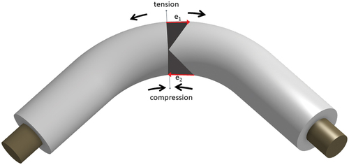
schematically represents the details of our consideration. Taking into account the flexible properties of the studied microwires, we see that the applied external mechanical bending stress induces the distribution of the internal stress inside the sample: from the maximum value of the tensile stress on the top surface (e1) to the maximum value of the compressive stress on the bottom surfaces of the sample (e2) [Citation27,Citation34]. Hence, a certain line inside the sample corresponds to zero value of the internal stress where the tension changed to compression (). It would be logical to consider that a given stress distribution across the sample diameter would cause the formation of a corresponding magnetic domain structure. We consider that the most probable magnetization distribution, corresponding to this type of internal stress distribution, is the longitudinal magnetization along the axis of the microwire [Citation13,Citation22]. As we saw in our experiment, this is exactly the longitudinal domain structure that was observed inside the L area.
Figure 4. Distribution of the mechanical stress in bended microwire.
Outside the L area, where the annealing was carried out without bending, there was no external bending stress. It led to the existence of a helical domain structure and the absence of the bistability effect. It is necessary to remark that for two studied samples the bend-annealing induced longitudinal distribution of the magnetic structure is different. Evidently, this difference is related with the difference in the radius of the bending.
It should also be noted that in two samples studied there is a spatial longitudinal transition zone in which the effect of induced bistability gradually disappears. Investigating the minor magnetic loops in the transition zone in detail, we found the following. The rectangular magnetic loop does not disappear sharply. The existence of the intermediate magnetic states was discovered. These states correspond to unstable helical states, which could be observed exclusively during the process of magnetization reversal. When we moved the measuring coil spatially into an area that was not subject to bending, the effect of the induced bistability disappeared completely.
As we can see, the bend-induced bistability effect is clearly related to the quick motion of a single longitudinal domain wall. This is a distinctive feature of the induced bistability effect, in contrast to the classical version of this effect, when a transverse domain structure was observed on the microwire surface [Citation32,Citation35].
A comparison of two samples with different bending radii () showed sufficient similarity of the hysteresis curves measured at the centre of the samples. Our attention was drawn to a certain difference in the magnitude of the magnetic jumps in two samples. Being small, this difference indicates a difference of several angular degrees between the magnetic states in two samples. This difference becomes more noticeable and significant as the measuring point moves towards the edge of the sample. Following the works [Citation24,Citation25,Citation36], we associate these effects with changes in the so-called curvature. In the determination of the curvature, following to the authors of these articles, the curvature is inversely proportional to the bend radius. Thus, the curvature of sample 2 is greater than the curvature of sample 1.
The model proposed by the authors of the mentioned articles is based on the concept of the curvature-induced magnetic anisotropy. It in turn leads to the existence of magnetic states different from those that exist in the unbent sample. In our experiments, this manifests itself in the difference in the magnetic jump both in samples subjected to annealing with different bending radii, and in each sample separately, when the measurement points correspond to the transition curvature down to zero.
An increase in curvature leads to an increase in compression and tension, as shown in . When the curvature of the sample during annealing is zero (no bending), there is no compression and tension. An increase in curvature leads to a greater stress gradient across the sample diameter between the stresses with opposite sign.
The influence of the stress annealing on the magnetic anisotropy of amorphous microwires has been studied in our paper [Citation37]. As we have demonstrated, the crystallization of Fe-rich amorphous microwires is usually observed at above 500°C [Citation37], perfectly amorphous structure of Fe71.7B13.4Si11Nb3Ni0.9 microwire is observed upon annealing at 550°C up to 2 h [Citation38]. On the other hand, excellent mechanical properties of glass-coated microwires (with tensile yield up to 2 GPa) have been reported elsewhere [Citation39]. Additionally, Young modulus temperature behaviour of Fe-rich amorphous materials usually presents elinvar properties, i.e. very small changes at heating before 300°C [Citation40]. Therefore, we believe that observed behaviour must be associated with changes in domain structure of studied amorphous Fe71.7B13.4Si11Nb3Ni0.9 microwire upon bending annealing. All these studies also indicate that at this annealing temperature, the surface irregularities do not appear.
As was shown in [Citation38], at the annealing temperature of 300 degrees, a magnetic softening effect is observed, which is associated with the annealing caused by the relaxation of internal stresses. This effect was observed in our microwire when annealed without bending.
Conclusion
Magnetic and magneto-optical studies were carried out in microwires previously subjected to bending annealing. The effect of bending annealing-induced magnetic bistability was discovered. Without annealing and after the annealing without bending, this effect was not observed. The effect of induced bistability was observed in a spatial region close to the length of the curved part of the sample. The longitude of this area varied with changes in the bend radius. The spatial disappearance of the effect of induced bistability occurred gradually as we moved towards the edges of the sample, which was not subjected to the bending during the annealing.
The induced bistability effect was accompanied by the rapid movement of a single longitudinal domain wall along the surface of the microwire that was not observed in the classical bistability effect. The existence of the longitudinal magnetic domain structure is the result of a particular distribution of the internal stress. This distribution represents a gradual transition from a compression to a tension across the microwire diameter.
Acknowledgments
This work was funded by the Spanish MICIN under PID2022-141373NB-I00, by the EU “Horizon Europe “under the “INFINITE” (HORIZON-CL5-2021-D5-01-06) project and by the government of the Basque Country under PUE_2021_1_0009, “Ayuda a Grupos Consolidados” (ref. IT1670-22) and Elkartek (MINERVA, MAGAF and ZE-KONP) projects.
Disclosure statement
No potential conflict of interest was reported by the author(s).
Additional information
Funding
References
- Ripka P, Vértesy G. Sensors based on soft magnetic materials panel discussion. J Magn Mater. 2000;215-216:795–8. doi:10.1016/S0304-8853(00)00291-2
- Zhukov A, Ipatov M, Corte-León P, et al. Giant magnetoimpedance in rapidly quenched materials. J Alloys Compd. 2020;814:152225. doi:10.1016/j.jallcom.2019.152225
- Mohri K, Uchiyama T, Panina LV, et al. Recent advances of amorphous wire CMOS IC magneto-impedance sensors: innovative high-performance micromagnetic sensor chip. J Sens. 2015;2015:1–8. doi:10.1155/2015/718069
- Chiriac H, Lupu N, Stoian G, et al. Ultrathin nanocrystalline magnetic wires. Crystals. 2017;7(2):48. doi:10.3390/cryst7020048
- Chizhik A, Zhukov A, Gonzalez J, et al. Spiral magnetic domain structure in cylindrically-shaped microwires. Sci Rep. 2018;8(1):1–7. doi:10.1038/s41598-018-33322-0
- Berganza E, Bran C, Jaafar M, et al. Domain wall pinning in FeCoCu bamboo-like nanowires. Sci Rep. 2016;6(1):29702. doi:10.1038/srep29702
- Alam J, Nematov M, Yudanov N, et al. High-frequency magnetoimpedance (MI) and stress-MI in amorphous microwires with different anisotropies. Nanomaterials. 2021;11:1208. doi:10.3390/nano11051208
- Knobel M, Vazquez M, Kraus L. Giant magnetoimpedance. In: Bruck E, editor Handbook of magnetic materials. Vol. 15. Amsterdam, The Netherlands: Elsevier; 2003. pp. 497–563.
- Zhukova V, Blanco JM, Ipatov M, et al. Engineering of magnetic softness and giant magnetoimpedance effect in Fe-rich microwires by stress-annealing. Scr Mater. 2018;142:10–14. doi:10.1016/j.scriptamat.2017.08.014
- Jiménez A, Calle E, Fernandez-Roldan JA, et al. Matteucci Effect and Single Domain Wall Propagation in Bistable Microwire under Applied Torsion. Phys Status Solidi A. 2021;218(18):21002842100284. doi:10.1002/pssa.202100284
- Alimohammadi S, Williams PI, Meydan T. A curvature sensor utilizing the Matteucci effect in amorphous wire. Sensors. 2023;23(3):1243. doi:10.3390/s23031243
- Skoric L, Donnelly C, Abert C, et al. Micromagnetic modeling of magnetic domain walls in curved cylindrical nanotubes and nanowires. Appl Phys Lett. 2021;118(24):242403. doi:10.1063/5.0050872
- Chizhik A, Gonzalez J, Zhukov A, et al. Review of helical magnetic structures in magnetic microwires. Chemosensors. 2022;10(8):291. doi:10.3390/chemosensors10080291
- Vazquez M, X CD. The magnetization reversal process in amorphous wires. IEEE Trans Magn. 1995;31(2):1229–1238. doi:10.1109/20.364813
- Mohri K, Humphrey FB, Kawashima K, et al. Large Barkhausen and Matteucci effects in FeCoSiB, FeCrSiB, and FeNiSiB amorphous wire. IEEE Trans Magn. 1990;26(5):1789–1791. doi:10.1109/20.104526
- Zhukova V, Zhukov A, Blanco JM, et al. Switching field fluctuations in a glass coated Fe-rich amorphous microwire. J Magn Magn Mat. 2002;249(1–2):131–135. doi:10.1016/S0304-8853(02)00520-6
- Soeda M, Takajo M, Yamasaki J, et al. Large Barkhausen discontinuities of die-drawn Fe-Si-B amorphous wire. IEEE Trans Magn. 1995;31:3877–3879. doi:10.1109/20.489802
- Vazquez M, Chiriac H, Zhukov A, et al. On the state-of-the-art in magnetic microwires and expected trends for scientific and technological studies. Phys Status Solidi A. 2011;208(3):493. doi:10.1002/pssa.201026488
- Makhnovskiy D, Fry N, Zhukov A. On different tag reader architectures for bistable microwires. Sens Actuators A Phys. 2011;166(1):133–140. doi:10.1016/j.sna.2010.11.002
- Sabol R, Klein P, Ryba T, et al. Novel applications of bistable magnetic microwires. Acta Phys Pol A. 2017;131(4):1150–1152. doi:10.12693/APhysPolA.131.1150
- Chizhik A, Gonzalez J, Zhukov A, et al. Circular magnetic bistability in co-rich amorphous microwires. J Phys D Appl Phys. 2003;36:419–422. doi:10.1088/0022-3727/36/5/301
- Castillo-Sepúlveda S, Corona RM, Landeros P, et al. Domain walls in curved thin surfaces. J Magn Magn Mater. 2020;500:166322. doi:10.1016/j.jmmm.2019.166322
- Sheka D. A perspective on curvilinear magnetism. Appl Phys Lett. 2021;118(23):230502. doi:10.1063/5.0048891
- Sheka D, Kravchuk VP, Gaididei Y, et al. Curvature effects in statics and dynamics of low dimensional magnets. J Phys A Math Theor. 2015;48(12):125202. doi:10.1088/1751-8113/48/12/125202
- Korniienko A, Kravchuk VP, Pylypovskyi OV, et al. Curvature induced magnonic crystal in nanowires. SciPost Phys. 2019;7(3):035. doi:10.21468/SciPostPhys.7.3.035
- Bittencourt GHR, Moreno R, Cacilhas R, et al. Curvature-induced emergence of a second critical field for domain wall dynamics in bent nanostripes. Appl Phys Lett. 2021;118(14):142405. doi:10.1063/5.0046848
- Nabias J, Asfour A, Yonnet JP. The impact of bending stress on the performance of Giant magneto-impedance (GMI) magnetic Sensors. Sensors. 2017;17(3):640. doi:10.3390/s17030640
- Corte-León P, Zhukova V, Blanco JM, et al. Engineering of domain wall propagation in magnetic microwires with graded magnetic anisotropy. Applied Materials Today. 2022;26:101263. doi:10.1016/j.apmt.2021.101263
- Gonzalez-Legarreta L, Corte-Leon P, Zhukova V, et al. Optimization of magnetic properties and GMI effect of thin co-rich microwires for GMI Microsensors. Sensors. 2020;20(6):1558. doi:10.3390/s20061558
- Stupakiewicz A, Chizhik A, Tekielak M, et al. Direct imaging of the magnetization reversal in microwires using all-MOKE microscopy. Rev Sci Instrum. 2014;85(10):103702. doi:10.1063/1.4896758
- Corte-Leon P, Zhukova V, Chizhik A, et al. Magnetic microwires with unique combination of magnetic properties suitable for various magnetic sensor applications. Sensors. 2020;20:7203. doi:10.3390/s20247203
- Varga R, Klein P, Sabol R, et al. Magnetically bistable microwires: properties and applications for magnetic field, temperature, and stress sensing. In: Zhukov A, editor. High performance soft magnetic materials. Springer series in materials science. Vol. 252. Cham: Springer; 2017. DOI:10.1007/978-3-319-49707-5_8
- Onufer J, Ziman J, Duranka P P, and Kravcák J. The study of Closure domain structure dynamics in bistable microwires using the technique of three-level field pulses. IEEE Trans Magn. 2019;55(1):2000106. doi:10.1109/TMAG.2018.2873250
- Daunys M, Rimovskis S. Analysis of circular cross-section element, loaded by static and cyclic elastic–plastic pure bending. Int J Fatigue. 2006;28(3):211–222. doi:10.1016/j.ijfatigue.2005.06.018
- Kabanov Y, Zhukov A, Zhukova V, et al. Magnetic domain structure of wires studied by using the magneto-optical indicator film method. Appl Phys Lett. 2005;87(14):142507. doi:10.1063/1.2077854
- Gaididei Y, Kravchuk V, Mertens F, et al. Localization of magnon modes in a curved magnetic nanowire. Low Temp Phys. 2018;44(7):634. doi:10.1063/1.5041428
- Corte-Leon P, Zhukova V, Blanco JM, et al. Engineering of magnetic properties and magnetoimpedance effect in Fe-rich microwires by reversible and irreversible stress-annealing anisotropy. J Alloys Compd. 2021;855:157460. doi:10.1016/j.jallcom.2020.157460
- Corte-Leon P, Zhukova V, Ipatov M, et al. The effect of annealing on magnetic properties of “thick” microwires. J Alloys Compd. 2020;831:150992. doi:10.1016/j.jallcom.2019.06.094
- Goto T. Fe–B and Fe–Si–B system alloy filaments produced by glass-coated melt spinning. Trans JIM. 1980;21(4):219–224. doi:10.2320/matertrans1960.21.219
- Kikuchi M, Fukamichi K, Masumoto T. Young’s modulus and delay time characteristics of ferromagnetic Fe-Si-B amorphous Alloys. Tohoku University. 1976;26:232–239.