
ABSTRACT
Many loss processes in perovskite solar cells (PSCs) take place at interfaces. One effective mitigation strategy is introducing carbon derivatives at the interface of the charge transport layers with the halide perovskite absorber and/or with the contacts. In this work, single-walled carbon nanotubes are incorporated into the hole transporting material (HTM), either as composites or as a separate layer on top of the HTM. Both organic and inorganic hole transport materials are studied to validate this approach for different types of HTMs. It is shown that the CNTs facilitate charge transport from perovskite to the back contact, regardless of the HTM used. The use of CNTs results in an increase in a significant increase in short circuit current and power conversion efficiency. This study illustrates how SWCNTs can be utilised to improve the properties of a wide range of HTMs, which will pave the way for more efficient and PSCs.
1. Introduction
The increasing global electricity demand and the negative impact of using fossil fuels on the environment motivate the development of clean and renewable energy technologies. Solar energy is a promising alternative to fossil fuels due to its sheer abundance (Cui et al. Citation2015; Ibn-Mohammed et al. Citation2017; Zhou et al. Citation2018). The past decade has seen the emergence of lead halide perovskite solar cells (PSCs). The ease of fabrication, abundance and low cost of materials, and high lab-scale power conversion efficiencies (PCEs) of up to 25.7% (Green et al. Citation2021) make PSCs a promising photovoltaic technology. The high PCE achieved in PSCs can be ascribed to the unique set of optoelectronic properties of lead halide perovskites, including; a tunable bandgap (Eg = 1.5-2.3 eV for pure lead-based perovskites) (Park Citation2015; Tu et al. Citation2017; Zhu et al. Citation2016; Mosconi et al. Citation2013), long charge carrier diffusion lengths, high charge carrier mobilities (∼35 cm2 V−1s−1) and high absorption coefficient (Herz Citation2017; Noh et al. Citation2013; Yin, Shi, and Yan Citation2014). PSCs are constructed by sandwiching the perovskite absorber between a hole and an electron transporting material (HTM and ETM). In the n-i-p structure, the ETM is deposited first, followed by perovskite and HTM, and vice versa for the p-i-n structure (Zhou et al. Citation2018; Green et al. Citation2021; Park Citation2015; Zhu et al. Citation2016; Herz Citation2017; Tong et al. Citation2016). PSCs using the n-i-p architecture generally show higher PCEs than their p-i-n counterparts (Best Research-Cell Efficiency Chart Citation2022). In n-i-p devices, the HTM plays a crucial role in charge extraction and stability, but not many materials possess the ability to execute both roles sufficiently (Zhou et al. Citation2018; Green et al. Citation2021; Park Citation2015; Tong et al. Citation2016; Cronin et al. Citation2017; Leijtens et al. Citation2015; Rajeswari et al. Citation2017). An ideal HTM needs energy levels matched to the perovskite, high hole mobility, thermal and chemical stability, and hydrophobicity to provide environmental stability (Zhou et al. Citation2018; Green et al. Citation2021; Park Citation2015; Tong et al. Citation2016; Cronin et al. Citation2017; Leijtens et al. Citation2015; Rajeswari et al. Citation2017). Two classes of HTMs have been used extensively in n-i-p mesoporous structures: (i) organic p-type semiconductors such as P3HT (Habisreutinger et al. Citation2014), Poly[bis(4-phenyl)(2,4,6-trimethylphenyl)amine (PTAA) (Khorasani et al. Citation2019), and 2,2’,7,7'-Tetrakis[N,N-di(4-methoxyphenyl)amino]-9,9'-spirobifluorene (spiro-OMeTAD) (Ko et al. Citation2018), and (ii) inorganic p-type semiconductors such as CuO, Cu2O, NiOx, CuI, CuSCN and CuIn(1-x)GaxS2 (Zhou et al. Citation2018; Green et al. Citation2021; Tong et al. Citation2016; Rajeswari et al. Citation2017; Juarez-Perez et al. Citation2016). Organic HTMs generally yield higher PCEs, but their high cost (due to complicated synthetic processes and high purity requirement), the need to use additives to optimise their conductivity, and their poor thermal, chemical, and environmental stability are significant drawbacks (Tong et al. Citation2016; Rajeswari et al. Citation2017). Inorganic HTMs on the other hand benefit from inexpensive fabrication using cost-effective and abundant materials and exhibit excellent stability. But a significant drawback is that inorganic HTMs need high processing temperatures to achieve high charge carrier mobility and low defect densities, which is incompatible with processing on top of lead halide perovskite (Tong et al. Citation2016; Rajeswari et al. Citation2017; Roose, Wang, and Abate Citation2019). There is thus much need to further improve the properties of HTMs for n-i-p PSCs.
In recent years, carbon derivatives have been used as a means to improve the performance of PSCs (Gong et al. Citation2021; Ferguson, Silva, and Zhang Citation2019; Hadadian, Smått, and Correa-Baena Citation2020). This includes graphdiyne (GDY) (Zhang et al. Citation2018), multi-walled carbon nanotubes (MWCNT) (Lee et al. Citation2015), single-walled carbon nanotubes (SWCNT, from here on CNTs) (Habisreutinger et al. Citation2014; Gatti et al. Citation2016; Shadrokh et al. Citation2020), reduced graphene oxide (RGO) (Gatti et al. Citation2016), and graphene oxide (GO) (Oo and Debnath Citation2017). These materials have been employed in several different ways: i) in the photoactive layer combined with perovskite, ii) as electrodes to replace costly Au and Ag electrodes or to improve and enable the charge transfer process by the electrode, iii) as an interlayer between perovskite and HTMs, and iv) as a composite with the HTM (Habisreutinger et al. Citation2014; Zhang et al. Citation2018; Lee et al. Citation2015; Gatti et al. Citation2016; Shadrokh et al. Citation2020; Oo and Debnath Citation2017; Nouri, Mohammadi, and Lianos Citation2018; Yang et al. Citation2018; Li et al. Citation2014; Wei et al. Citation2015). For example, Kartikay et al. (Citation2021) reported the application of functionalised NiOx (f-NiOx) and MWCNT composite as hole transport material in n-i-p low-temperature processed carbon counter electrode-based PSCs, which resulted in the 11.36% PCE (see Table S1). Since the MWCNTs are multi-layer of graphene with larger diameters and have lower electronic properties than SWCNTs, in which by increasing the concentration of MWCNTs, the series resistance of the layer is increased which results in the suppression of the photovoltaic parameters e.g. fill factor (Charles et al. Citation1981; Lee et al. Citation2014). However, the SWCNTs are a single layer of graphene with ultra-high surface and distinct electronic properties, where the charge carriers can be transported through SWCNTs without scattering. Moreover, SWCNTs have beneficial mechanical and thermodynamical properties (Heise et al. Citation2009; Bati et al. Citation2019; Asgari and Lohrasbi Citation2012).
In this work, the integration of SWCNTs in NiOx and P3HT (additive-free) HTMs was studied, both as a composite (HTM&CNT) and a separate layer between the HTM and the back contact (HTM/CNT), with the aim to better understand the influence of SWCNT incorporation on device efficiency and stability. NiOx was chosen, as its properties are representative of inorganic HTMs, including a wide bandgap and a simple and cost-effective synthesis method (Oo and Debnath Citation2017; Zhang et al. Citation2016; Zhang et al. Citation2016; Yang et al. Citation2017; Abdollahi Nejand, Ahmadi, and Shahverdi Citation2015; Wang et al. Citation2016; Cao et al. Citation2017). Among the organic HTMs, P3HT was selected as it does not need any additives to boost conductivity (Habisreutinger et al. Citation2014), which would complicate studying the impact of CNTs. SWCNTs were chosen, as these can be easily processed into a web-like surface morphology, providing a facile and low-cost method to create an interconnected network of carbon derivatives (Lee et al. Citation2015; Kartikay et al. Citation2021). SWCNTs are either incorporated in the HTM, or used as a separate layer between the HTM and back electrode. Both strategies lead to a marked increase in efficiency, mainly by increasing Jsc. SEM images show a uniform distribution of SWCNTs, both when they are incorporated into the HTMs, and when they are deposited as a separate layer on top, indicating that they can act as a charge carrier bridge between perovskite, HTM and back contact. PL results show increased quenching when SWCNTs are used for both HTMs, indicating charge extraction is enhanced. The P3HT&CNT composite shows the strongest quenching. In addition, electrochemical impedance spectroscopy (EIS) shows the lowest charge transfer resistance for P3HT&CNT. As a result, all HTMs show improved efficiency in combination with SWCNTs. NiO and SWCNTs perform equally well as a composite and as separate layers, but for P3HT the composite shows superior performance, which is ascribed to the strong interaction of P3HT with CNTs, leading to the highest efficiency.
2. Experimental
2.1. Materials
Lead(II) iodide (PbI2 (99.9%), Sharif Solar), titanium(IV) isopropoxide (TTIP (99.999%), Sigma-Aldrich), poly(3-hexylthiophene-2,5-diyl) (P3HT(Mw 50,000-75,000), Sigma-Aldrich), Ni(NO3)2.6H2O (99.99%, Merck), N,N-dimethylformamide (DMF (99.8%), Merck), Isopropyl Alcohol (IPA (98%), Merck), Ethanol (99.8%, Merck), methylammonium iodide (MAI (99%), homemade), TiO2 paste (Dyesol 30 NR-D) and SWCNT (length∼30 µm, diameter = 1-2 nm, resistivity = 0.1-0.15 Ω.cm, INSCX) were purchased and used without further purification.
2.2. Synthesis of niox
For the preparation of the NiOx solution, 240 mg of Ni (NO3)2·6H2O was dissolved in 20 ml of pure isopropanol (IPA) and stirred continuously overnight. The green NiOx solution was filtered by a 0.45 μm PTFE filter.
2.3. Preparation of niox&CNT ink
To prepare NiOx&CNT, at first, 5 mg of CNT was added into 1 ml IPA under sonication for 3 h, 150 μl of the resulting suspension was added to 1 ml NiOx solution under stirring for 3 h, followed by 60 min sonication.
2.4. Preparation of P3HT&CNT ink
To prepare P3HT&CNT composite solution, first, 15 mg of P3HT was dissolved in 1 ml chlorobenzene at 70°C for 3 h under continuous stirring to obtain a homogeneous solution, then 150 μl of 5 mg ml−1 of CNT in chlorobenzene was added to P3HT solution under stirring for 3 h, followed by 60 min sonication.
2.5 Solar cell fabrication
Fluorine-doped tin oxide (FTO) glasses (10 Ω □−1) were etched with zinc powder and HCl (4 M) to form the electrode pattern. The FTO glasses were cleaned separately in boiling DI water and 4 steps of an ultrasonic bath for 15 min, including deionised water with detergent, acetone, ethanol, 2-propanol, and finally dried by clean and hot air. The glass was exposed to a vacuum oven at 200 °C for 2 h before use. A 50-70 nm thin layer of TiO2 was spin-coated from 250 µl TTIP and HCl (2 M) solution in ethanol at 2500 rpm for 30 s and then annealed at 500 °C for 30 min. A mesoporous TiO2 layer was deposited by spin-coating a diluted TiO2 paste in ethanol (ratio 1:6) at 2000rpm for 30 s. After the spin coating procedure, the substrates were heated at 120 °C for 10 min and then gradually annealed at 500 °C for 30 min.
The PbI2 films were made from dissolving PbI2 powder in DMF (1 M) filtered by a 450 nm PTFE filter and then spin-coated at 5000 rpm for 30 s, the films were annealed at 100 °C for 15 min. After cooling down, the PbI2 films were placed in a petri dish at a distance of about 1 cm above the CH3NH3I (MAI) powder at 150°C for 3 h in an oven to convert the PbI2 film to MAPbI3. After cooling to room temperature, the MAPbI3 films were washed with isopropanol to remove excess MAI and were dried at 100°C for 10 min. For control devices, NiOx and P3HT were deposited by spin-coating at 3000 rpm for 30 s. For NiOx/CNT or P3HT/CNT devices, NiOx or P3HT was spin-coated at 3000 rpm for 30 s followed by deposition of CNTs. NiOx&CNT and P3HT&CNT composites were spin-coated at 3000 rpm for 30 s. Then, the samples were kept at 70°C for 10 min. Finally, an 80 nm layer of gold was deposited on the top of HTM to form a back contact. The active area of the electrodes was fixed with a 0.09 cm2 shadow mask.
2.6 Characterisation
The thin films of CH3NH3PbI3 perovskite were characterised by field-emission scanning electron microscopy (FESEM, TESCAN, Mira 3-XMU), X-ray diffraction (XRD, D8-Advance Bruker), The UV-Vis absorbance properties was determined by an Avantes spectrometer (AVASPEC-ULS2048L) in a range from 200 nm to 900 nm. Photoluminescence (PL) measurements were performed by using a nitrogen laser (NL 100) with an excitation wavelength of 337 nm.
Current-voltage (J-V) curves of the CH3NH3PbI3 PSCs were measured by a homemade parameter analyzer sweeping from -0.1 to 1.2 V a t a scan rate of 50 mV s−1, illuminated under a solar simulator (AM 1.5G, 100 mW cm−2, SharifSolar). The active area of the devices was defined by a 0.09 cm2 aperture mask. Impedance spectroscopy measurements were carried out under illumination with an Autolab 302 N, with different DC bias potentials from 100 to 1000 mV and from 1 Hz to 1 MHz. The spectra were fitted using Z-View software.
3. Result and discussion
3.1 Device architecture
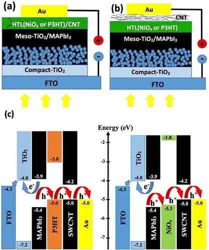
shows the device architecture of HTM&CNT ((a)) and HTM/CNT ((b)) devices and the energy band alignment of PSCs employing P3HT, NiOx, and CNTs ((c)). As can be seen from (c), the energy levels of perovskite and the HTMs need to be well aligned to facilitate efficient charge transport from perovskite to the Au electrode. In addition, CNTs create a separate pathway for the extraction of holes toward the Au electrode.
Figure 1. The device structure of (a) HTM&CNT, (b) HTM/CNT, and (c) energy level of P3HT (left) (Ye et al. Citation2016) and NiOx (right)-based (Yin et al. Citation2017) PSCs.
3.2 Scanning electron microscopy
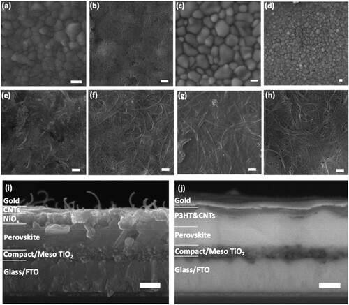
shows FESEM images of the pristine perovskite layer (verified by XRD pattern, see Figure S1a) and in combination with the different HTM layers (verified by XRD pattern, see Figure S1b for NiOx HTM) deposited on top. As shown in (a), the perovskite layer is uniform and pinhole-free, and consists of grains with a diameter of several hundred nanometer. (b) shows a NiOx layer on top of perovskite, consisting of small particles forming a uniform and dense layer. The morphology of the underlying perovskite layer cannot be seen, further suggesting the NiOx particles form a thick conformal layer. (c,d) show a conformal covering of the perovskite layer by P3HT over multiple length scales. In contrast to NiOx, the underlying perovskite morphology is still visible, suggesting the P3HT layer is relatively thin. For NiOx&CNT ((e)) CNTs are randomly distributed throughout the NiOx layer. Some aggregation of CNTs is taking place, which may be due to the low solubility of CNTs in isopropanol alcohol (IPA), and the magnetic properties of NiOx that lead to the aggregation of CNTs. (f) illustrates the uniformly dispersed layer of CNTs on top of NiOx and perovskite. In this case, CNTs are much less aggregated than for the composite. (g) shows the P3HT&CNT layer on perovskite, showing excellent complete coverage of the CNTs by P3HT to form a uniform layer of the P3HT&CNT composite. P3HT/CNT is shown in (h), forming a uniform and dense layer, similar to the layer of CNTs formed on top of NiOx in (f). (i,j), demonstrate the cross-section of prepared devices based on NiOx/CNT and P3HT&CNT, respectively. The FTO, TiO2, perovskite, HTMs and gold layers can be clearly distinguished. Thus, as can be seen in FESEM images, by applying the CNTs into the HTM layers and/or depositing them on HTMs separately, CNTs form a carbon layer as an interface. The CNTs can act as a bridge that connects the perovskite layer and HTM, or HTM and back contact, to transfer holes in the perovskite layer to the HTM and back contact, aiding charge extraction.
Figure 2. FESEM top views of (a) perovskite film applied on a TiO2 mesoporous layer, (b) NiOx film on perovskite (c), and (d) P3HT film on perovskite (e) NiOx&CNT layer on perovskite, (f) NiOx/CNT layer on perovskite (g) P3HT&CNT layer on perovskite, (h) P3HT/CNT layer on perovskite. The scale bar corresponds to 500 nm. Cross-sectional FESEM image of the perovskite solar devices based on (i) NiOx/CNT, and (j) P3HT&CNT (a)-(i) are secondary electron images, (j) is a backscattered electron image. The scale bar corresponds to 250 nm.
3.3 Optical characterization
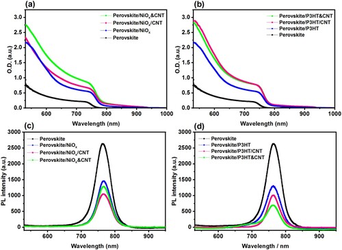
To investigate the influence of the HTMS on the optical properties of perovskite, we studied their UV-Vis absorption and photoluminescence (PL) spectra. (a,b) demonstrate UV-Vis absorption spectra of the samples consisting of NiOx-based HTMs and P3HT-based HTMs on perovskite, respectively. As can be seen, all the samples exhibit a higher absorption in the visible region (400-700 nm) as compared with the pristine perovskite. This increase is mainly caused by scattering by the HTM and CNTs, as is evidenced by the below bandgap signal. In addition, the annealing step (70°C) after HTM deposition may enhance the quality of the perovskite crystals and improve absorption. (c,d) illustrates the PL spectra of the samples in a Glass/Perovskite/HTM structure, excited at a wavelength of 337 nm. The high-intensity PL peak of the perovskite lies at 765 nm, and it tends to be quenched by the presence of different HTMs. The quenching of the PL peak is due to the charge transfer between perovskite and HTM. Thus, a more pronounced quenching of PL is indicative of better charge extraction from the perovskite to the HTM. As can be seen, both HTM&CNT and HTM/CNT strategies lead to increased quenching (and thus improved charge extraction). It is interesting to note that HTM/CNT shows similar quenching for both HTMs, but that for NiOx&CNT quenching decreases, whereas for P3HT&CNT quenching increases. This could be due to how P3HT effectively encapsulates the CNTs, preventing direct contact between perovskite and the CNTs. Because CNTs are not charge-selective, direct contact between perovskite and CNTs can lead to relatively high resistance and compromised hole transport (Habisreutinger, Nicholas, and Snaith Citation2017).
Figure 3. UV-Vis absorption spectra of (a) NiOx-based and (b) P3HT-based HTMs deposited on FTO/C-TiO2/Meso-TiO2/Perovskite structure. Photoluminescence spectra of (c) NiOx-based, and (d) P3HT-based devices on the glass/perovskite films.
3.4 Electrochemical impedance spectroscopy
To gain a better understanding of the effect of CNTs on the recombination rate and charge transfer resistance at the perovskite/HTM interface, the EIS spectra of the samples were measured under illumination. (a,b) show EIS data for P3HT&CNT and NiOx/CNT samples by applying different voltages in the frequency range of 10 Hz to 1 MHz. The devices have only one semicircle in their Nyquist plots, which can be attributed to the charge transfer resistance (Rt) at the interface between the perovskite and HTM (Thakur et al. Citation2017; Wang et al. Citation2019; Zheng et al. Citation2017), and displaying no obvious semicircle for charge recombination (Thakur et al. Citation2017; Wang et al. Citation2019; Zheng et al. Citation2017). As the voltage increases towards the open-circuit voltage (Voc), the radius of the semicircle decreases. A smaller radius indicates a reduction of Rt and faster charge transfer at the interface between the HTM or ETM and the perovskite (Thakur et al. Citation2017; Wang et al. Citation2019; Ahn et al. Citation2018). The series resistance (Rs), which includes the resistances of FTO, TiO2, perovskite, and Au electrodes, is 12 Ω for the P3HT&CNT device and slightly above 13 Ω for the NiOx/CNT device and remains unchanged at different voltages due to the similar device structure. In (c) reference devices employing NiOx and P3HT as HTM are compared to those using NiOx/CNT and P3HT&CNT, which showed the most PL quenching. Both HTMs show a significant reduction in Rt upon the introduction of CNTs. According to previous reports (Zheng et al. Citation2017), a smaller Rt is indicative of more efficient charge injection and. This translates into an enhancement of Jsc, as can be seen in the J-V plot (see , and ), where Jsc follows the same trend as Rt, i.e. the reference HTMs have higher Rt and lower Jsc than the HTMs with CNTs, and NiOx HTMs have higher Rt and lower Jsc than the P3HT HTMs.
Figure 4. Nyquist plots of the devices with (a) NiOx/CNT and (b) P3HT&CNT HTMs for different applied bias, and (c) comparison between Nyquist plots of devices using NiOx, P3HT, NiOx/CNT and P3HT&CNT as HTM, under illumination at the biased voltage of 0.8 V (inset: the equivalent circuit model used for EIS analysis).
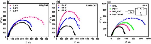
Figure 5. J-V curves of perovskite solar devices with different HTMs a) P3HT and b) NiOx, after 8 days of fabrication kept at room temperature, 35-40% RH, and dark condition. and (c) comparison of photoconversion efficiency of NiOx, P3HT, NiOx /CNT and P3HT&CNT devices during 90 days.
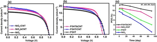
Table 1. Photovoltaic parameters of the perovskite solar devices with different HTMs, 8 devices were used for each condition.
3.5 Solar cell performance
(a, b) shows the photocurrent density-voltage (J-V) characterisation of PSCs fabricated by using the different HTMs. presents the results of the photovoltaic parameters for all samples. In PSCs employing NiOx, the record efficiency is achieved for NiOx/CNT devices ((a)), but average efficiencies are similar for NiOx/CNT and NiOx&CNT, which may indicate that the primary role of the CNTs is to improve charge transfer between the HTM and the back contact. In contrast, in PSCs employing P3HT, the highest record and average device efficiency is achieved for P3HT&CNT devices ((b)), in line with the trend in charge transport that was found from PL.
The presence of CNTs results in a significant increment of Jsc and PCE (see , and ) due to the improvement of fast hole extraction. Moreover, as can be seen in the band energy diagrams (see (c)), the energy alignment of P3HT and Au (5.0 eV) can be another reason for the higher photovoltaic performance of P3HT&CNT than P3HT/CNT, since the energy level of P3HT and Au are the same, making injection harder, the CNT provides a more aligned pathway for the charges to reach Au. P3HT&CNT shows the best performance, which may be due to the ability of CNTs to be functionalised with P3HT (Yang et al. Citation2017) and result in a uniform layer ((g)).
The J-V characteristics of the P3HT&CNT and NiOx/CNT cells were monitored over 90 days in 35-40% humidity at room temperature to investigate their stability. (c) shows the PCE of P3HT, NiOx, P3HT&CNT and NiOx/CNT devices for 90 days. It can be seen that after eight days the CNT devices stabilised and reached the highest efficiencies, which is consistent with previous reports (Gatti et al. Citation2016; Nouri, Mohammadi, and Lianos Citation2018). Moreover, P3HT&CNT devices showed a slower decrease in PCE compared to NiOx/CNT, where the devices retained 80% and 65% of their initial PCE after 90 days, respectively. In contrast, devices using NiOx or P3HT as HTM only retain 10% and 38%. This difference in stability is ascribed to the hydrophobic nature of the CNTs, which protects the perovskite against moisture. The presence of P3HT/CNT leads to delay of degradation because of two reasons, (i) CNTs play as a shielding layer against the penetration of moisture due to their hydrophobic property, and (ii) polymeric properties of P3HT and the formation of supramolecular CNT-polymer hybrids with high hydrophobicity form a protecting layer on top of the perovskite. Overall results demonstrate the promising application of CNTs as a composite with different HTMs and/or as an interlayer between HTM and electrode.
4. Conclusions
HTMs used in PSCs need both excellent charges for transporting properties and long-term stability. In n-i-p PSCs, many HTMs only offer excellent charge transport (organic HTMs) or long-term stability (inorganic HTMs). In this study, we have shown that CNTs can be used to enhance the properties of organic (P3HT) and inorganic (NiOx) HTMs in n-i-p PSCs. The CNTs can act as a bridge between the HTM and the back contact. PL and EIS results suggest this aids charge extraction, resulting in a marked increase in Jsc and PCE. The fabricated devices exhibit promising stability as a result of the formation of a more uniform HTM layer by the introduction of CNTs. We show the merit of CNTs as a low-cost material that can be used to boost the performance of a wide range of HTMs, which will be important for the commercialisation of PSCs.
gsol_a_2204363_sm3100.docx
Download MS Word (155.5 KB)Data availability
Data is available on request from the authors.
Disclosure statement
No potential conflict of interest was reported by the author(s).
References
- Abdollahi Nejand, B., V. Ahmadi, and H. R. Shahverdi. 2015. “New Physical Deposition Approach for Low Cost Inorganic Hole Transport Layer in Normal Architecture of Durable Perovskite Solar Cells.” ACS ACS Applied Materials & Interfaces 7 (39): 21807–21818. doi:10.1021/acsami.5b05477.
- Ahn, N., I. Jeon, J. Yoon, E. I. Kauppinen, Y. Matsuo, S. Maruyama, and M. Choi. 2018. “Carbon-Sandwiched Perovskite Solar Cell.” Journal of Materials Chemistry A 6 (4): 1382–1389. doi:10.1039/C7TA09174E.
- Asgari, M., and E. Lohrasbi. 2012. ISRN Electrochemistry 2013: e564784.
- Bati, A. S. R., L. Yu, S. A. Tawfik, M. J. S. Spencer, P. E. Shaw, M. Batmunkh, and J. G. Shapter. 2019. “Electrically Sorted Single-Walled Carbon Nanotubes-Based Electron Transporting Layers for Perovskite Solar Cells.” iScience 14: 100–112. doi:10.1016/j.isci.2019.03.015.
- Best Research-Cell Efficiency Chart | Photovoltaic Research | NREL: Golden, CO, USA, 2022.
- Cao, J., H. Yu, S. Zhou, M. Qin, T.-K. Lau, X. Lu, N. Zhao, and C.-P. Wong. 2017. “Low-Temperature Solution-Processed NiOx Films for Air-Stable Perovskite Solar Cells.” Journal of Materials Chemistry A 5 (22): 11071–11077. doi:10.1039/C7TA02228J.
- Charles, J. P., M. Abdelkrim, Y. H. Muoy, and P. Mialhe. 1981. “A Practical Method of Analysis of the Current-Voltage Characteristics of Solar Cells.” Solar Cells 4 (2): 169–178. doi:10.1016/0379-6787(81)90067-3.
- Cronin, H. M., K. D. G. I. Jayawardena, Z. Stoeva, M. Shkunov, and S. R. P. Silva. 2017. “Effects of ambient humidity on the optimum annealing time of mixed-halide Perovskite solar cells.” Nanotechnology 28 (11): 114004. doi:10.1088/1361-6528/aa5bec.
- Cui, J., H. Yuan, J. Li, X. Xu, Y. Shen, H. Lin, and M. Wang. 2015. “Recent Progress in Efficient Hybrid Lead Halide Perovskite Solar Cells.” Science and Technology of Advanced Materials 16 (3): 036004. doi:10.1088/1468-6996/16/3/036004.
- Ferguson, V., S. R. P. Silva, and W. Zhang. 2019. “Carbon Materials in Perovskite Solar Cells: Prospects and Future Challenges.” Energy & Environmental Materials 2 (2): 107–118. doi:10.1002/eem2.12035.
- Gatti, T., S. Casaluci, M. Prato, M. Salerno, F. Di Stasio, A. Ansaldo, E. Menna, A. Di Carlo, and F. Bonaccorso. 2016. “Boosting Perovskite Solar Cells Performance and Stability through Doping a Poly-3(hexylthiophene) Hole Transporting Material with Organic Functionalized Carbon Nanostructures.” Advanced Functional Materials 26 (41): 7443–7453. doi:10.1002/adfm.201602803.
- Gong, K., J. Hu, N. Cui, Y. Xue, L. Li, G. Long, and S. Lin. 2021. “The Roles of Graphene and Its Derivatives in Perovskite Solar Cells: A Review.” Materials & Design 211: 110170. doi:10.1016/j.matdes.2021.110170.
- Green, M., E. Dunlop, J. Hohl-Ebinger, M. Yoshita, N. Kopidakis, and X. Hao. 2021. “Solar cell efficiency tables (version 57).” Progress in Photovoltaics: Research and Applications 29 (1): 3–15. doi:10.1002/pip.3371.
- Habisreutinger, S. N., T. Leijtens, G. E. Eperon, S. D. Stranks, R. J. Nicholas, and H. J. Snaith. 2014. “Carbon Nanotube/Polymer Composites as a Highly Stable Hole Collection Layer in Perovskite Solar Cells.” Nano Letters 14 (10): 5561–5568. doi:10.1021/nl501982b.
- Habisreutinger, S. N., R. J. Nicholas, and H. J. Snaith. 2017. “Carbon Nanotubes in Perovskite Solar Cells.” Advanced Energy Materials 7 (10): 1601839. doi:10.1002/aenm.201601839.
- Hadadian, M., J.-H. Smått, and J.-P. Correa-Baena. 2020. “The Role of Carbon-Based Materials in Enhancing the Stability of Perovskite Solar Cells.” Energy & Environmental Science 13 (5): 1377–1407. doi:10.1039/C9EE04030G.
- Heise, H. M., R. Kuckuk, A. K. Ojha, A. Srivastava, V. Srivastava, and B. P. Asthana. 2009. “Characterisation of Carbonaceous Materials Using Raman Spectroscopy: A Comparison of Carbon Nanotube Filters, Single- and Multi-Walled Nanotubes, Graphitised Porous Carbon and Graphite.” Journal of Raman Spectroscopy 40 (3): 344–353. doi:10.1002/jrs.2120.
- Herz, L. M. 2017. “Charge-Carrier Mobilities in Metal Halide Perovskites: Fundamental Mechanisms and Limits.” ACS Energy Letters 2 (7): 1539–1548. doi:10.1021/acsenergylett.7b00276.
- Ibn-Mohammed, T., S. C. L. Koh, I. M. Reaney, A. Acquaye, G. Schileo, K. B. Mustapha, and R. Greenough. 2017. “Perovskite Solar Cells: An Integrated Hybrid Lifecycle Assessment and Review in Comparison with Other Photovoltaic Technologies.” Renewable and Sustainable Energy Reviews 80: 1321–1344. doi:10.1016/j.rser.2017.05.095.
- Juarez-Perez, E. J., M. R. Leyden, S. Wang, L. K. Ono, Z. Hawash, and Y. Qi. 2016. “Role of the Dopants on the Morphological and Transport Properties of Spiro-MeOTAD Hole Transport Layer.” Chemistry of Materials 28 (16): 5702–5709. doi:10.1021/acs.chemmater.6b01777.
- Kartikay, P., D. Sadhukhan, A. Yella, and S. Mallick. 2021. “Enhanced Charge Transport in Low Temperature Carbon-Based n-i-p Perovskite Solar Cells with NiOx-CNT Hole Transport Material.” Solar Energy Materials and Solar Cells 230: 111241. doi:10.1016/j.solmat.2021.111241.
- Khorasani, A., M. Marandi, R. Khosroshahi, M. Malekshahi Byranvand, M. dehghani, A. Iraji Zad, F. Tajabadi, and N. Taghavinia. 2019. “Optimization of CuIn1–XGaXS2 Nanoparticles and Their Application in the Hole-Transporting Layer of Highly Efficient and Stable Mixed-Halide Perovskite Solar Cells.” ACS Applied Materials & Interfaces 11 (34): 30838–30845. doi:10.1021/acsami.9b08714.
- Ko, Y., Y. Kim, C. Lee, Y. Kim, and Y. Jun. 2018. “Investigation of Hole-Transporting Poly(triarylamine) on Aggregation and Charge Transport for Hysteresisless Scalable Planar Perovskite Solar Cells.” ACS Applied Materials & Interfaces 10 (14): 11633–11641. doi:10.1021/acsami.7b18745.
- Lee, J., H. Kang, J.-Y. Hwang, S. W. Kim, and S. Baik. 2014. “Flexible Photoanodes of TiO2 Particles and Metallic Single-Walled Carbon Nanotubes for Flexible Dye-Sensitized Solar Cells.” Carbon 79: 337–345. doi:10.1016/j.carbon.2014.07.075.
- Lee, J., M. M. Menamparambath, J.-Y. Hwang, and S. Baik. 2015. “Hierarchically Structured Hole Transport Layers of Spiro-OMeTAD and Multiwalled Carbon Nanotubes for Perovskite Solar Cells.” ChemSusChem 8 (14): 2358–2362. doi:10.1002/cssc.201403462.
- Leijtens, T., G. E. Eperon, N. K. Noel, S. N. Habisreutinger, A. Petrozza, and H. J. Snaith. 2015. “Stability of Metal Halide Perovskite Solar Cells.” Advanced Energy Materials 5 (20): 1500963. doi:10.1002/aenm.201500963.
- Li, Z., S. A. Kulkarni, P. P. Boix, E. Shi, A. Cao, K. Fu, S. K. Batabyal, et al. 2014. “Laminated Carbon Nanotube Networks for Metal Electrode-Free Efficient Perovskite Solar Cells.” ACS Nano 8 (7): 6797–6804. doi:10.1021/nn501096h.
- Mosconi, E., A. Amat, Md. K. Nazeeruddin, M. Grätzel, and F. De Angelis. 2013. “First-Principles Modeling of Mixed Halide Organometal Perovskites for Photovoltaic Applications.” The Journal of Physical Chemistry C 117 (27): 13902–13913. doi:10.1021/jp4048659.
- Noh, J. H., S. H. Im, J. H. Heo, T. N. Mandal, and S. I. Seok. 2013. “Chemical Management for Colorful, Efficient, and Stable Inorganic–Organic Hybrid Nanostructured Solar Cells.” Nano Letters 13 (4): 1764–1769. doi:10.1021/nl400349b.
- Nouri, E., M. R. Mohammadi, and P. Lianos. 2018. “Construction of Perovskite Solar Cells Using Inorganic Hole-Extracting Components.” ACS Omega 3 (1): 46–54. doi:10.1021/acsomega.7b01775.
- Oo, T. T., and S. Debnath. 2017. AIP Conference Proceedings 1902: 020015.
- Park, N.-G. 2015. “Perovskite Solar Cells: An Emerging Photovoltaic Technology.” Materials Today 18 (2): 65–72. doi:10.1016/j.mattod.2014.07.007.
- Rajeswari, R., M. Mrinalini, S. Prasanthkumar, and L. Giribabu. 2017. “Emerging of Inorganic Hole Transporting Materials For Perovskite Solar Cells.” The Chemical Record 17 (7): 681–699. doi:10.1002/tcr.201600117.
- Roose, B., Q. Wang, and A. Abate. 2019. Advanced Energy Materials 9 (5): 1803140.
- Shadrokh, Z., Sh. Sousani, S. Gholipour, and Y. Abdi. 2020. “Enhanced Photovoltaic Performance and Stability of Perovskite Solar Cells by Interface Engineering with Poly(4-vinylpyridine) and Cu2ZnSnS4&CNT.” Solar Energy 201: 908–915. doi:10.1016/j.solener.2020.03.093.
- Thakur, U. K., A. M. Askar, R. Kisslinger, B. D. Wiltshire, P. Kar, and K. Shankar. 2017. “Halide Perovskite Solar Cells Using Monocrystalline TiO2 Nanorod Arrays as Electron Transport Layers: Impact of Nanorod Morphology.” Nanotechnology 28 (27): 274001. doi:10.1088/1361-6528/aa75ab.
- Tong, X., F. Lin, J. Wu, and Z. M. Wang. 2016. “High Performance Perovskite Solar Cells.” Advanced Science 3 (5): 1500201. doi:10.1002/advs.201500201.
- Tu, Y., J. Wu, Z. Lan, X. He, J. Dong, J. Jia, P. Guo, J. Lin, M. Huang, and Y. Huang. 2017. “Modulated CH3NH3PbI3−xBrx Film for Efficient Perovskite Solar Cells Exceeding 18%.” Scientific Reports 7 (1): 44603. doi:10.1038/srep44603.
- Wang, Y., W.-Y. Rho, H.-Y. Yang, T. Mahmoudi, S. Seo, D.-H. Lee, and Y.-B. Hahn. 2016. “Air-stable, hole-conductor-free high photocurrent perovskite solar cells with CH3NH3PbI3–NiO nanoparticles composite.” Nano Energy 27: 535–544. doi:10.1016/j.nanoen.2016.08.006.
- Wang, Y., H. Zhao, Y. Mei, H. Liu, S. Wang, and X. Li. 2019. “Carbon Nanotube Bridging Method for Hole Transport Layer-Free Paintable Carbon-Based Perovskite Solar Cells.” ACS Applied Materials & Interfaces 11 (1): 916–923. doi:10.1021/acsami.8b18530.
- Wei, Z., H. Chen, K. Yan, X. Zheng, and S. Yang. 2015. “Hysteresis-Free Multi-Walled Carbon Nanotube-Based Perovskite Solar Cells with a High Fill Factor.” Journal of Materials Chemistry A 3 (48): 24226–24231. doi:10.1039/C5TA07714A.
- Yang, Y., H. Chen, X. Zheng, X. Meng, T. Zhang, C. Hu, Y. Bai, S. Xiao, and S. Yang. 2017a. “Ultrasound-Spray Deposition of Multi-Walled Carbon Nanotubes on NiO Nanoparticles-Embedded Perovskite Layers for High-Performance carbon-Based Perovskite Solar Cells.” Nano Energy 42: 322–333. doi:10.1016/j.nanoen.2017.11.003.
- Yang, W. S., B.-W. Park, E. H. Jung, N. J. Jeon, Y. C. Kim, D. U. Lee, S. S. Shin, et al. 2017b. “Iodide Management in Formamidinium-Lead-Halide–Based Perovskite Layers for Efficient Solar Cells.” Science 356 (6345): 1376–1379. doi:10.1126/science.aan2301.
- Yang, Y., N. D. Pham, D. Yao, H. Zhu, P. Yarlagadda, and H. Wang. 2018. “Inorganic p-type Semiconductors and Carbon Materials Based Hole Transport Materials for Perovskite Solar Cells.” Chinese Chemical Letters 29: 1242–1250.
- Ye, J., X. Li, J. Zhao, X. Mei, and Q. Li. 2016. “Efficient and Stable Perovskite Solar Cells Based on Functional Graphene-Modified P3HT Hole-Transporting Layer.” RSC Advances 6 (43): 36356–36361. doi:10.1039/C6RA03466G.
- Yin, W.-J., T. Shi, and Y. Yan. 2014. “Unique Properties of Halide Perovskites as Possible Origins of the Superior Solar Cell Performance.” Advanced Materials 26 (27): 4653–4658. doi:10.1002/adma.201306281.
- Yin, X., Z. Yao, Q. Luo, X. Dai, Y. Zhou, Y. Zhang, Y. Zhou, et al. 2017. “High Efficiency Inverted Planar Perovskite Solar Cells with Solution-Processed NiOx Hole Contact.” ACS Applied Materials & Interfaces 9 (3): 2439–2448. doi:10.1021/acsami.6b13372.
- Zhang, Y., L. Tan, Q. Fu, L. Chen, T. Ji, X. Hu, and Y. Chen. 2016. “Enhancing the Grain Size of Organic Halide Perovskites by Sulfonate-Carbon Nanotube Incorporation in High Performance Perovskite Solar Cells.” Chemical Communications 52: 5674–5677.
- Zhang, X., Q. Wang, Z. Jin, Y. Chen, H. Liu, J. Wang, Y. Li, and S. (Frank) Liu. 2018. “Graphdiyne Quantum Dots for Much Improved Stability and Efficiency of Perovskite Solar Cells.” Advanced Materials Interfaces 5 (2): 1701117. doi:10.1002/admi.201701117.
- Zheng, X., H. Chen, Q. Li, Y. Yang, Z. Wei, Y. Bai, Y. Qiu, D. Zhou, K. S. Wong, and S. Yang. 2017. “Boron Doping of Multiwalled Carbon Nanotubes Significantly Enhances Hole Extraction in Carbon-Based Perovskite Solar Cells.” Nano Letters 17 (4): 2496–2505. doi:10.1021/acs.nanolett.7b00200.
- Zhou, D., T. Zhou, Y. Tian, X. Zhu, and Y. Tu. 2018. “Perovskite-Based Solar Cells: Materials, Methods, and Future Perspectives.” Journal of Nanomaterials 2018: 1–15. doi:10.1155/2018/8148072.
- Zhu, W., C. Bao, F. Li, T. Yu, H. Gao, Y. Yi, J. Yang, G. Fu, X. Zhou, and Z. Zou. 2016. “A Halide Exchange Engineering for CH3NH3PbI3−Br Perovskite Solar Cells with High Performance and Stability.” Nano Energy 19: 17–26. doi:10.1016/j.nanoen.2015.11.024.