?Mathematical formulae have been encoded as MathML and are displayed in this HTML version using MathJax in order to improve their display. Uncheck the box to turn MathJax off. This feature requires Javascript. Click on a formula to zoom.
ABSTRACT
This work presents the materials selection process, the design and the dimensioning process of a latent heat storage tank that works between a high temperature heat pump and an Organic Rankine Cycle unit. The selected heat storage material is the S117 Phase Change Material that has a melting point at 117°C matches the operational temperature of the system at approximately 120°C. The tank configuration is selected for optimised heat transfer process, resulted from practical experience of the project partners and it is described in details in the document. The simulation results from the Computational Fluid Dynamic study of the tank are also presented here. This work should be useful for engineers designing compact heat storage tanks for medium temperature applications.
1. Introduction to latent heat storage
Amongst thermal heat storage techniques, latent heat storage (LHS) is particularly attractive due to its ability to provide high energy storage density and store heat at a constant temperature (Sharma et al. Citation2009). This aspect is particularly important as the project focuses on low temperature high efficiency micro-thermal energy storage (TES) architecture. Latent heat storage is reported (Pielichowska and Pielichowski Citation2014) to be the most efficient method of storing thermal energy. In contrast to sensible heat storage (SHS), LHS systems require far less storage volume due to their large heat storage capacity per unit volume (Biencinto et al. Citation2021; Nkwetta et al. Citation2014; Pielichowska and Pielichowski Citation2014). Indeed, LHS systems can store 5–14 times more heat per unit volume than SHS materials such as water, masonry, or rock (Sharma et al. Citation2009).
The materials used in the latent heat storage are known as Phase Change Materials (PCMs), because they change their physical phase from solid to liquid and vice versa. The constant temperature at which the phase change occurs is called melting temperature. At that temperature, these materials melt when an amount of heat is added, but their temperature is not increased. At a temperature lower than that, the material freezes and releases an equal amount of heat in the form of latent heat of fusion or energy of crystallisation. The most prominent advantage of latent storage is the option to store energy within a narrow temperature range close to the phase change temperature (Bauer et al. Citation2012; https Citation2021).
Therefore, two temperatures describe the charge and discharge process (IEA Solar Heating and Cooling Task Citation2020):
Charging Temperature Tchar: The charging temperature has to be above the melting temperature for the PCM to melt during the charging process. The minimum necessary temperature difference between charging and melting temperature depends on the heat exchanger design.
Consumer Temperature Tcons: The consumer temperature depends on the type of application and should be below the melting temperature in order to utilise the PCM’s melting enthalpy. The discharge temperature is slightly higher than the consumer temperature. The minimum necessary temperature difference between the melting and the consumer temperature depends on the heat exchanger design.
The properties of a suitable PCM are a combination of the following characteristics (Pielichowska and Pielichowski Citation2014; Stutz et al. Citation2017; TESSe2b project Citation2016):
Thermal properties: small phase transition temperature range (within 1–2°C of desired freeze/melt point), high phase transition latent heat per unit volume, high specific heat capacity per unit volume, high thermal conductivity of both phases.
Physical properties: small volume change on phase transformation, low vapour pressure at the operating temperature, favourable phase equilibrium, congruent melting of the PCM, large density.
Kinetic properties: no supercooling, high nucleation rate, quick crystallisation for successful heat energy recovery.
Chemical properties: no degradation on repeated phase transitions (long life cycle and chemical stability), completely reversible freeze/melt cycle, compatibility with the containers, non-toxic, non-flammable and non-explosive.
Market properties: low cost, readily available.
In practice, no PCM fully meets all the criteria mentioned above (Pielichowska and Pielichowski Citation2014). Therefore, selecting a PCM is a compromise between its properties, performance, system requirements and economic constraints (TESSe2b project Citation2016).
1.1. Material types
This section presents the general characteristics and features of the most common PCM material types appropriate for low and medium temperature applications, but it is out of the scope of this study to analytically investigate the PCM materials, which have been extensively studied in the literature (Crespo et al. Citation2019; Cunha and Eames Citation2016; Ling and Poon Citation2013; Mao, Liu, and Peng Citation2018; Pielichowska and Pielichowski Citation2014; Shao et al. Citation2023; Stutz et al. Citation2017; Task Citation42 Citation2021). The PCMs commonly used can be generally divided into two principal types: inorganic and organic.
1.1.1. Inorganic PCM
The most common inorganic PCMs are hydrated salts. The general formula of a hydrated salt is MxNy·nH2O. The water molecules inside the crystals of a hydrate mostly make coordinate covalent bonds and hydrogen bonds to the positively charged metal ions (cations) of the salt. These water molecules may be referred to as water of crystallisation or water of hydration. During heating, hydrated salt loses its water of crystallisation by absorbing a certain amount of energy, called the enthalpy of dehydration (ΔHdehyd). While cooling or being exposed to the atmosphere, water molecules from the surroundings are easily captured by salt crystals and release the thermal energy corresponding to ΔHhyd. The dehydration and hydration processes are similar to melting and freezing thermodynamically. When heated, a salt hydrate is usually converted either to its anhydrous form or to a salt hydrate with fewer moles of water.
During heating, an undesired phenomenon appears; most of the PCMs melt incongruently (Pielichowska and Pielichowski Citation2014). The normal condition is congruent melting; the salt should be soluble in the hydration water, at its melting temperature. However, incongruent melting is when the salt is only partially soluble in the hydration water, at the melting temperature. This phenomenon often leads to differences between the enthalpy of fusion (heat stored) and the enthalpy of solidification (heat retrieved), thus affecting the amount of energy that can be reliably retrieved from storage (Cantor Citation1979). This also leads to density differences, phase separation and sedimentation in containers causing serious technical problems (Pielichowska and Pielichowski Citation2014).
During cooling, another unsuitable characteristic appears; supercooling. In supercooling, the liquid state can be cooled to below its freezing point whilst remaining a liquid, and this makes the associated phase change ineffective. Another concern of the inorganic PCMs is that they degrade after repeated phase change cycles and thus, they can become inoperative (Ling and Poon Citation2013).
Despite these disadvantages, salt hydrates are generally considered as suitable materials for TES applications because they possess large latent heat of fusion meaning that a lesser amount of material is needed to store a given amount of energy (http Citation2021). Salt hydrates also have appropriate phase transition temperature, high volumetric heat storage capacity and good thermal conductivity. Additionally, they are very competitive in terms of economy and profitability, they are readily available and they are non-flammable (Ling and Poon Citation2013).
There is a special requirement in the use of salt hydrate PCMS: They must be stored and used in air-tight containers to prevent exposure to the atmosphere. Failure to do this would result in loss of water via evaporation, which would severely affect the performance of the PCM.
Molten salts are another type of Inorganic PCMs. Typical molten salts, such as NaNO2, NaNO3 and KNO3, are considered in the literature for solar steam power systems mainly working in the temperature range from 200 to 600°C (Adinberg, Zvegilsky, and Epstein Citation2010).
Metallic alloys are another type of Inorganic PCMS. They are used as high temperature PCMs as they offer high thermal reliability and repeatability. Among the alloys, eutectic aluminium alloys are investigated for high temperature TES systems, because of their suitable phase change temperature, high latent heat density and good thermal stability. It has been reported that after 1000 thermal cycles, the melting temperature is changed by 3-5 K and the latent heat of fusion is slightly decreased.
1.1.2. Organic PCM
Organic PCMs can be further described as paraffin and non-paraffin types. Most of the organic PCMs are chemically stable, safe and non-reactive. Also, they have an ability to melt congruently without segregation and have self-nucleating properties that are compatible with traditional construction materials without posing any significant problems of supercooling.
Paraffin waxes are saturated hydrocarbons with CnH2n+2 formula. Their melting points range from 20°C up to 70°C, depending on the number of carbon atoms in the chain (Bauer et al. Citation2012; Ling and Poon Citation2013; Yang et al. Citation2023). The more carbon atoms present in the chain, the higher the melting point and the higher the heat of fusion of the paraffin wax.
These materials are widely available and inexpensive, non-corrosive and non-toxic, they are chemically stable, their phase transformation is rapid and they have negligible supercooling. The literature also reports excellent thermal stability resulting from the lack of cycling effect on its properties, as well as degrading of thermal behaviour due to contact with metals (Nkwetta et al. Citation2014). It has been reported that the properties of commercial paraffin waxes are stable even after 1000–2000 cycles. The above reasons make paraffin wax one of the most popular PCMs for storing low temperature heat.
The undesirable properties of paraffin wax are: low thermal conductivity, large volume change during melting is large (about 10%), low volumetric energy density compared to salt hydrates and low thermal diffusivity. Additionally, they are flammable and non-compatible with plastic containers.
Fatty acids are another type of organic non-paraffin PCMs. Fatty acids possess desirable thermodynamic and kinetic characteristics for low temperature heat storage. Their melting point is similar to paraffin wax and they have excellent melting and freezing properties and they exhibit low phase transition volume changes with very little or no supercooling when freezing. However, they are about three times more expensive than paraffin wax, are mildly corrosive and possess a disagreeable odour.
1.2. Container types
Not only do the operational parameters of the heat storage system, such as heat transfer fluid temperature, flow rate and initial temperature affect the thermal storage performance, but also the specific container characteristics, such as the presence of fins and nanoparticles, and the container geometry and orientation play a dominant role (Keshteli et al. Citation2022; Punniakodi and Senthil Citation2021).
PCMs can be encapsulated in shell-and-tube, cylindrical, triplex-tube, spherical, rectangular, and trapezoidal containers (Punniakodi and Senthil Citation2021). In shell-and-tube containers, the PCM is filled in between shell-and-tube and the PCM’s melting is high due to natural convection in a solar-driven shell-and-tube TES. A recent study in these containers (Rana, Zunaid, and Kumar Citation2022) showed that the lowest melting time is obtained by rectangular tubes, followed by elliptical tubes and circular tubes. The multitube heat exchanger used in cylindrical containers performs well in melting the PCM because of its increased surface area. More heat transfer occurs in PCM due to the change in HTF’s flow characteristics from laminar to turbulent flow. Triplex tubes are less used when compared with shell-and-tube and cylindrical heat exchanger. Here, the PCM is placed between the inner and outer tubes and the PCM’s melting rate is increased. Considering solar thermal applications around 100°C, the most appropriate container that could be used is the shell-and-tube. As shell-and-tube is commonly used in industries, many modifications are possible to suit the requirements of solar thermal systems. The cylindrical, triplex-tube, rectangular and trapezoidal could be used for lower temperature levels, at around 60°C (Punniakodi and Senthil Citation2021).
The addition of fins increases the melting rate by 71%, the use of nanoparticles increases the melting rate by 62.6%, whereas the change in container orientation improves the melting rate up to 47.5% (Punniakodi and Senthil Citation2021). Fins’ geometrical parameters, such as length, number, thickness, spacing, angle and shape affect the heat transfer effectiveness, but in recent studies (Eslami, Khosravi, and Fallah Kohan Citation2021; Herbinger and Groulx Citation2022; Zamani and Keshavarz Citation2023) it has been shown that this relationship is rather complicated and finding an optimum fin arrangement for a wide range of operating conditions is a difficult task. This happens because even though the fins increase the heat transfer rate, using an excessive number of fins or an improper shape and arrangement can decrease the PCM’s energy storage density. Especially for solar thermal systems, the addition of fins is strongly suggested for faster charging and discharging (Punniakodi and Senthil Citation2021).
Container materials are preferably stainless steel and aluminium for organic and inorganic PCMs to avoid corrosion (Punniakodi and Senthil Citation2021).
1.3. Application to this study
Developing reliable heat storage systems using PCM is not a straightforward process; it is rather a challenge, as a number of issues are encountered (Bauer et al. Citation2012; Christensen Citation1983; Stutz et al. Citation2017). However, PCM solutions are readily available in the market for many niche applications and PCM storage technology is one of the most promising technologies. Indeed, the potential for thermal storage systems based on PCM technologies is vast; it is estimated that about 800 GWhth (equal to 18 million m3 of water) is the capacity of installed solar water storages for households in the year 2012 (IEA Solar Heating and Cooling Task Citation2015).
Especially for heat storage applications near 120°C, the demonstration of the PCMs is currently under research and development (IEA Solar Heating and Cooling Task Citation2015). Therefore, continuous research and development efforts are required to reduce costs further and to enhance the scaling-up of this technology.
Primarily for temperatures near 120°C, which is the desired phase change temperature of this study, the latent heat storage system has the greatest potential to be energy efficient, for reasons mentioned above. The selection of the specific PCM that will be used is based firstly on the definition of desired criteria, secondly, on the criteria hierarchy and finally, on the analysis of their thermodynamic properties. The PCM material selection is inevitably bound to technical and economical give and take compromises; the ultimate goal is that the selected PCM complies with as many of the defined criteria as possible.
2. Description of the InnoSolPower system
This work is implemented at the framework of the InnoSolPower EU CSP ERANET project, which aims at designing and demonstrating a novel, low temperature heat storage system especially for concentrated solar power (CSP) systems. The system concept of the project is seen in . Solar energy is harvested from the solar block that consists of parabolic trough collectors, a heat exchanger and a small buffer storage, to provide more uniform heat to the heat pump. The heat exchanger is necessary, since the heat transfer fluid inside the parabolic trough collectors is different from that in the heat pump supply side. The heat pump receives the solar thermal energy and produces high temperature heat, at approximately 120°C. This heat is either stored in the TES tank or it is transferred directly to the ORC unit for electricity production, depending on the user profile, the status of the TES and the solar irradiation. The specific operation parameters for this study are shown in .
Figure 1. InnoSolPower system concept.
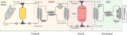
Table 1. Main operation parameters.
This storage concept does not involve mass transfer or chemical reactions in the storage medium and it is called indirect storage. In this concept, two different media exist; the first serves as the heat carrier and the latter as the storage medium. The storage medium is contained inside the storage tank and the heat carrier, through a heat exchanger, flows in and out of the tank, directed towards the Heat Pump or the Organic Rankine Cycle, depending on the operation mode of the system. This storage system is based on a single tank concept for the PCM.
2.1. Design methodology
2.1.1. PCM selection
Following an extensive market analysis of the available PCM materials, there are four candidate PCM materials: H115, S117, H120 and A133. The final selection is the outcome of a multi-criteria analysis, called Analytic Hierarchy Process (AHP) that follows the prerequisites of the system concept and the prioritisation strategy (Saaty Citation1987). The AHP decomposes a complex decision-making problem into a system of hierarchies. There are various criteria under which the energy storage materials can be compared, but for this study, the following five evaluation criteria apply:
Phase change temperature > TORC_out
The final cost of material, including transportation
Chemical stability and durability > 1000 thermal cycles
Corrosiveness and toxicity
Delivery time
The Analytic Hierarchy Process for selecting the PCM material was built in the MathCad software. The comparison matrix A for the selection of the PCM material is a real 5*5 matrix Each entry aij of the matrix A represents the importance of the ith criterion relative to the jth criterion ().
Table 2. Comparison matrix A of criteria.
The scale of priorities, or normalised weights, are applied by making pairwise comparisons of all the criteria. The vector of criteria weights is calculated as ().
Table 3. Weight of criteria.
Next, for a fixed criterion, the AHP assigns a score to each option according to the decision maker’s pairwise comparisons of the options based on that criterion. The higher the score, the better the performance of the option with respect to the considered criterion. The result is a matrix of paired comparisons among the options (PCM) with respect to each criterion. Criteria are five, so there are five such matrices.
The final step is to combine the criteria weights and the options scores, thus determining a global score for each option and a consequent ranking. The global score for a given option is a weighted sum of the scores it obtained with respect to all the criteria. This is done by multiplying the relative normalised weight of each option with its corresponding normalised weight value for each alternative and summing over the options for each alternative. The overall priority scale is ().
Table 4. Final ranking of the candidate PCMs.
This gives a final priority of 0.418 for S117, the most preferred material, with H120 as runner-up with a priority of 0.325. The main substance contained in the S117 PCM is Magnesium Chloride Hexahydrate MCH, whose thermophysical properties are extensively described in the literature (Cantor Citation1979; Chen, Li, and Zhang Citation2018; El-Sebaii et al. Citation2009; Höhlein, König-Haagen, and Brüggemann Citation2017; IEA Solar Heating and Cooling Task Citation2015) and summarised in the .
Table 5. Thermodynamic properties of magnesium chloride hexahydrate MCH.
Test tube experiments with MCH showed that it exhibits no disparity between enthalpy of crystallisation (heat retrieved) and enthalpy of fusion (heat stored) and thus, it melts almost congruently (Cantor Citation1979). The experiments also observed the melting of MCH to happen over a range of temperatures; some liquid was visible at 117°C and the sample completely liquefied at 120°C. It has to be noted here that at temperatures around 140°C the irreversible side reaction dehydration due to overheating appears:
This reaction is undesirable because it reduces the amount of active material and produces HCl gas that is toxic and corrosive to the system (Zondag et al. Citation2010). Therefore, during melting, the temperature should be kept below 140°C.
On the other hand, crystallisation appears to be congruent at 117°C, with almost no supercooling observed, even after 500 and 1002 cycles (Cantor Citation1979; El-Sebaii et al. Citation2009). Experiments for 500 cycles showed that it exhibits no disparity between enthalpy of crystallisation (heat retrieved) and enthalpy of fusion (heat stored) and thus, it melts almost congruently (Cantor Citation1979; El-Sebaii et al. Citation2009). Therefore during melting, MCH forms a saturated aqueous phase and a solid phase. Due to their density difference, the solid phase is gathered at the bottom of the container. This phenomenon is irreversible, which means during freezing, the solid phase will not be combined with the saturated solution to form the original salt hydrate.
Regarding stability and durability, limited work is reported concerning thermal cycling tests of MCH (El-Sebaii et al. Citation2009; Shukla, Buddhi, and Sawhney Citation2008). Recent experimental thermal stability test results with MCH indicate a small shift of the melting temperature up to higher values, but the change is less than 0.3 K in absolute values. The results showed that the melting enthalpy increases within the first cycles and decreases afterwards subsequently to about 99% of the starting value (Höhlein, König-Haagen, and Brüggemann Citation2017). The addition of extra water to the MCH after each 50 cycles and the hermetically sealing of the container (El-Sebaii et al. Citation2009; Rathod and Banerjee Citation2013) are two methods for stability improvement. Same authors investigated the changes in thermophysical properties of MCH after 1000 thermal cycles in a sealed container under the extra water principle (El-Sebaii et al. Citation2011). They found that the MCH solidifies almost without supercooling; except in few cases where it showed maximum of 0.1-3.5°C of supercooling. They found that the melting temperature and latent heat of fusion are slightly changed with repeating thermal cycling and that almost no supercooling is observed during solidification. The results indicate that MCH is recommended as a promising storage material (Höhlein, König-Haagen, and Brüggemann Citation2017; Li et al. Citation2011).
2.1.2. Tank and heat transfer fluid materials selection
The tank is made of steel alloy 304 or 310, since it is not in contact with the corrosive heat storage material and therefore, there is no reason to select a higher steel grade. On the contrary, the encapsulation units should be made of high-grade stainless steel (such as 316L), since they are in contact with the heat storage material. The insulation material of the tank is mineral wool.
The heat transfer fluid can be either water at 5 bar pressure, or Therminol SP thermal oil from Eastman Chemical Company.
2.1.3. Tank design configuration
The concept is to have indirect storage process, where the heat carrier is different from the storage medium. The general concept of the tank configuration consists of the following characteristics:
The storage tank is horizontally placed, following the direction of the PCM cylinders. Following long technical discussions among authors and PCM provider, horizontally layout is preferred instead of vertical layout, since temperature gradients should be avoided so as to allow the PCM to operate in a proper manner. The horizontal placement of the cylinders containing PCM ensure that the temperature stratification is kept to a minimum.
The selected PCM is sensitive to the presence of air and water. Therefore, it needs to be encapsulated in an air/watertight container.
The selected PCM is also sensitive to large temperature gradients (stratification) therefore, a vertical design is not suitable since the PCM column that is parallel to the direction of HTS is the length of the LTES tank.
Inside the tank, there are closed cylinders filled with the PCM. The cylinders are horizontally placed, since the temperature stratification has to be minimum.
Inside the tank and outside the cylinders, there is a heat transfer fluid, flowing in and out.
The dimensioning process followed the flowchart of equations of the authors’ previous research work (Christodoulaki et al. Citation2020). The dimensions of the tank and the tank subcomponents stems from the initial requirement of having a total PCM volume of 2 m3 and of the requirement to place the PCM inside numerous horizontal cylinders of 0.05 m internal diameter maximum, so as to minimise the temperature stratification phenomenon. The following table shows the detailed dimensions of the cylinders.
Following the calculation of the total number of cylinders required to achieve the total PCM volume, the dimensioning of the tank is elaborated as follows: Starting from the number of cylinders required for the total volume of PCM, the internal diameter of the tank was calculated. However, the cylinders cannot be just left inside the tank, but they have to be placed in a grid and at a distance of at least 1mm between them to ensure the flow of the heat transfer fluid and to avoid excessive pressure differences. So, the total number of cylinders that fit inside the tank are 293.
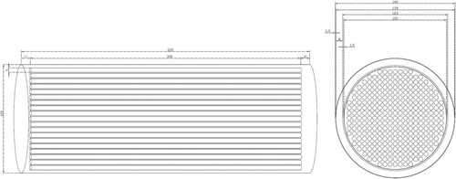
Regarding the length of the tank and subsequently, the length of the cylinders, this work investigates cylinders with 3 m length, for practical reasons; this option will facilitate the filling of the cylinders with PCM and other practical issues related to the construction of the tank. Indeed, if the cylinders were shorter, then more cylinders would have to be filled in with the hot melted PCM ().
Table 6. Dimensions of cylinders and tank.
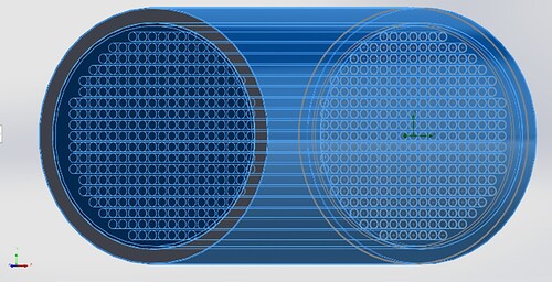
The cross section of the tank is seen in the . The cylinders are placed in grid position, with 1 mm apart. This distance ensures symmetry of the construction and homogeneous external volumetric flow, as well as it enables less pressure losses of the heat transfer fluid.
Figure 2. Left: Side view of the tank consisting of 1 pack of cylinders. Right: Cross section and dimensions (cm) of the TES tank with 293 tubes inside.
2.2. Simulation process
2.2.1. Introduction
The thermal analysis of the above tank is implemented in the SOLIDWORKS Flow Simulation software.
The detailed description of the tank design, application of specific dimensions and selections of materials is out of the scope of this publication, however, the results of the simulations will be presented, both for the tank charging process and the discharging process. Due to the unique design of the tank, validation of the simulation results is difficult, however, the results will be validated with the experimental data of the pilot plant that will be constructed at a later stage of the project.
2.2.2. Simulation model
In this section, the most crucial parameters during the simulation model development will be shown. The detailed process of the simulation model development can be found in the Annex.
Due to the SOLIDWORKS limitation of not being able to dynamically simulate the phase change materials and in other words, not being able to simulate the process of melting and solidification, the filling material is of limited interest in this study. Therefore, a basic assumption had to be inserted at this point; the outside surface of the cylinders had to be at a constant temperature and in particular, for S117 at 117°C.
In contrast to the cylinders filling, the heat transfer material is of crucial importance in this study. Therefore, Therminol SP oil will be the material that will be flowing outside of the cylinders, in and out of the tank.
The chosen material for the tank and the cylinders is the built-in material steel alloy 321.
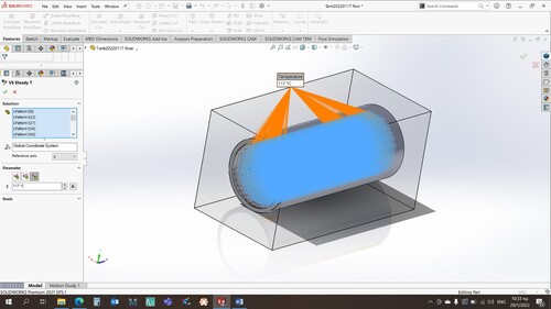
The first boundary condition of this thermodynamic study is the inlet conditions of the heat transfer oil, namely Tin = 135°C, m = 1.46 kg/sec. The second boundary condition is the temperature of the tank envelope, Tamb = 20°C. The third boundary condition that had to be inserted in the software is the temperature of the 293 cylinders envelope. In the case of PCM material, the envelope of the cylinders (steel material) was assumed to have a steady temperature of 117°C. This approximation is close to reality, since the 117°C is the phase change temperature of the PCM material. So, when heat is applied to the PCM, through the heat transfer oil external flow, this heat is stored as latent heat inside the cylinders and its temperature remains constant throughout the whole process ().
Figure 3. Application of constant wall temperature of cylinders at 117°C.
For the discharging scenario, the temperature of the cylinders is set at 130°C and the temperature of the heat transfer fluid is 102°C.
2.2.3. Simulation results for charging
The results, as set during the definition of the simulation goals are:
- Tfluid.out °C, the temperature of the Therminol SP exiting the tank,
- Qloss W, the heat losses from the tank envelope to the ambient,
- Qfluid W, the heat transferred from/to the Therminol SP fluid.
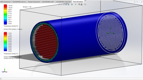
The following figures visualise the CFD simulation implemented for the TES charging with the storage material S117 and the Therminol SP fluid ().
Table 7. CFD simulation results of TES charging process.
The charging power of the tank is the calculated power of the fluid which is approximately 27 kW.
The surface temperature plots in show that the model produces logical results. More specifically, the temperature of the tank envelope is about 25°C, which means that the Mineral wool insulation works. The temperature gradient of the Mineral wool insulation, from the inner part of the tank to the outer shell of the tank, is also logical. But apart from visualising the temperatures, this figure is also used as a cross check for the input data. The temperature of the cylinders is 117°C, which validates the inputs used in the model.
Figure 4. Temperature surface plots for the tank envelope and the cylinders at steady-state for the charging process. The fluid flow inlet is at the centre of the axes.
shows the temperatures inside the whole tank, as seen from above. The fluid flow is from left to right and this explains why the temperature of the fluid flowing between the cylinders is decreased, from left to right. Indeed, the inlet temperature is set at 135°C and the outlet bulk temperature has been calculated at 126.65°C. A similar temperature gradient is seen for the steel tank and the Mineral wool insulation and this is thermodynamically reasonable. Moreover, the presence of the insulation is justified, since it prevents the tank from losing excessive heat. The results also show that the thickness of the insulation is sufficient for this application, since the outer average temperature of the tank envelope is 22.3°C, which is close to the ambient temperature, set at 20°C ().
Figure 5. Temperature cut contours in the longitudinal section for the whole tank at steady-state for the charging process. The fluid flow is from left (axis centre) to right.
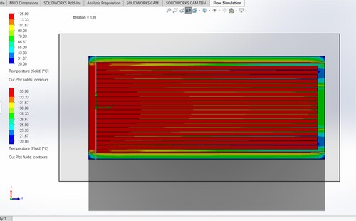
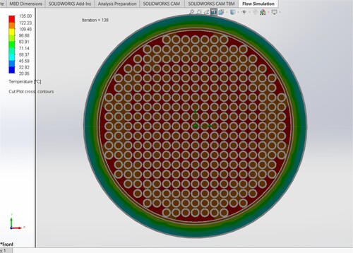
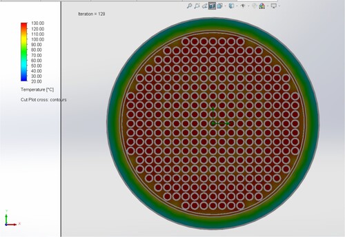
Figure 6. Temperature cut plots in the transverse section, near the exit of the tank, at steady-state for the charging process.
2.2.4. Simulation results for discharging
Similarly to the charging scenario, the results of the discharging process are reasonable and the visualisations indicate that the model works and a successful cross check of the input data to the model has been elaborated. As an example, shows the temperatures inside the whole tank, as seen from above. The fluid flow is from left to right and it can be seen that the temperature of the fluid flowing between the cylinders is now increased, from left to right. Indeed, the inlet temperature is set at 102°C and the outlet bulk temperature has been calculated at 114.8°C. A similar temperature gradient is seen for the steel tank and the Mineral wool insulation and this is thermodynamically reasonable. Moreover, the presence of the insulation is justified, since it prevents the tank from losing excessive heat. The results also show that the thickness of the insulation is sufficient for this application, since the outer temperature of the tank envelope ranges from 21.24°C to 22.58°C, which is very close to the ambient temperature, set at 20°C ().
Figure 7. Temperature surface plots for the tank envelope and the cylinders at steady-state for the discharging process. The fluid flow inlet is at the centre of the axes.
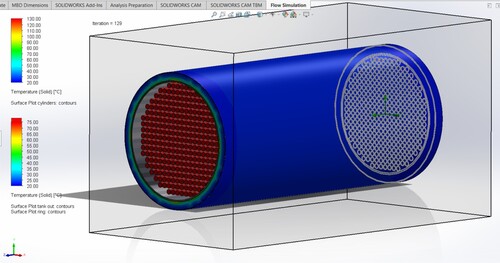
Table 8. CFD simulation results of TES discharging process.
The discharging power of the tank is the calculated power of the fluid, in this case is approximately 48 kW ( and ).
Figure 8. Temperature cut plots in the longitudinal section for the whole tank at steady-state for the discharging process.
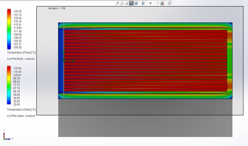
Figure 9. Temperature cut plots in the transverse section, near the exit of the tank, at steady-state for the discharging process.
3. Discussion
The objective of this study was the identification of the most appropriate heat storage type for the technical prerequisites of the InnoSolPower project. The storage tank under consideration should provide continuous generation of heat at relatively low temperatures (<160°C) and for a duration of six hours. The operational temperature of the heat storage tank material should be also suitable for the corresponding high-temperature heat pump to be coupled upstream of the heat storage tank and Organic Rankine Cycle engine to be coupled downstream of the heat storage tank. Under these circumstances, latent heat storage was applied since it has the greatest potential to be energy and cost efficient.
The extensive literature and market in-desk research that was implemented in this work, resulted in five different PCMs that could be potentially used. These were carefully selected through the definition of the most important criteria; phase change temperature, purchase and transportation cost, chemical stability and durability, corrosiveness and toxicity and delivery time. The Analytic Hierarchy Process was then elaborated with the view to decompose this complex decision-making problem and finally, identified the most appropriate PCM for this specific application: the S117.
The definition of the materials used, the specific technical characteristics and the dimensions of the subcomponents allowed the detailed design of the tank in a CAD software. The definition of the operational parameters of the tank allowed the simulation of the thermal performance of the tank, in charging and discharging process into the SOLIDWORKS Flow simulation software. The results showed that the charging and discharging power of the tank is approximately 27 and 48 kW, respectively. Temperature surface plots for the tank envelope and the cylinders during charging and discharging as well as temperature cut contours in the longitudinal section for the whole tank were produced. The results showed that the tank operates as expected, so the subsequent project activities that is the tank physical construction, can now initiate. Minor adjustments to the design could be allowed, in order to align the design with the constructional limitations and market availability of subcomponents. This work is useful for mechanical engineers and heat storage tank developers and explains the detailed steps that were followed, from the concept identification up to the tank thermal simulation.
Acknowledgements
This work has been elaborated in the framework of InnoSolPower project, which has received funding from the European Union’s Horizon 2020 Research and Innovation Programme CSP ERA-NET (G.A. 838311).
Disclosure statement
No potential conflict of interest was reported by the author(s).
Additional information
Funding
References
- Adinberg, R., D. Zvegilsky, and M. Epstein. 2010. “Heat Transfer Efficient Thermal Energy Storage for Steam Generation.” Energy Conversion and Management 51 (1): 9–15. https://doi.org/10.1016/j.enconman.2009.08.006
- Bauer, T., W. Steinmann, D. Laing, and R. Tamme. 2012. “Thermal Energy Storage Materials and Systems.” Annual Review of Heat Transfer Vol. 15: 131–177. https://doi.org/10.1615/AnnualRevHeatTransfer.2012004651..
- Biencinto, M., R. Bayóna, L. González, R. Christodoulaki, and E. Rojas. 2021. “Integration of a Parabolic-Trough Solar Field with Solid-Solid Latent Storage in an Industrial Process with Different Temperature Levels.” Journal of Applied Thermal Engineering 184 (116263). https://doi.org/10.1016/j.applthermaleng.2020.116263.
- Cantor, S. 1979. “DSC Study of Melting and Solidification of Salt Hydrates.” Thermochemica Acta 33: 69–86. https://doi.org/10.1016/0040-6031(79)87030-6
- Chen, W., W. Li, and Y. Zhang. 2018. “Analysis of Thermal Deposition of MgCl2·6H2O Hydrated Salt in the Sieve-Plate Reactor for Heat Storage.” Applied Thermal Engineering 35: 95–108. https://doi.org/10.1016/j.applthermaleng.2018.02.043.
- Christensen, C. 1983. Advanced Phase-Change Storage: Analysis of Materials and Configurations. NREL Solar Energy Institute, SERl/TP-255-2018, June 1983. Advanced Phase-Change Storage: Analysis of Materials and Configurations (nrel.gov). Accessed 26 June 2021.
- Christodoulaki, R., M. Biencinto, L. González, V. Drosou, and L. Valenzuela. 2020. “Dimensioning Tool for the Balance of Plant of Solar Heat for Industrial Processes Systems.” 13th International Conference on Solar Energy for Buildings and Industry Eurosun 2020, Athens, Greece, 1–4.
- Crespo, A., C. Barreneche, M. Ibarra, and W. Platzer. 2019. “Latent Thermal Energy Storage for Solar Process Heat Applications at Medium-High Temperatures – A Review.” Solar Energy 192: 3–34. https://doi.org/10.1016/j.solener.2018.06.101.
- Cunha, J. P., and P. Eames. 2016. “Thermal Energy Storage for Low and Medium Temperature Applications Using Phase Change Materials – A Review.” Applied Energy 177: 227–238. https://doi.org/10.1016/j.apenergy.2016.05.097
- Eastman Chemical Company. 2023. Therminol SP Heat Transfer Fluid, Technical Data Sheet. https://productcatalog.eastman.com/tds/ProdDatasheet.aspx?product=71093454&pn=Therminol(SP(Heat(Transfer(Fluid#_ga=2.246179332.1644567165.1642149477-1222670087.1642149477.
- El-Sebaii, A. A., S. Al-Amir, F. M. Al-Marzouki, Adel S. Faidah, A. A. Al-Ghamdi, and S. Al-Heniti. 2009. “Fast Thermal Cycling of Acetanilide and Magnesium Chloride Hexahydrate for Indoor Solar Cooking.” Energy Conversion and Management 50 (12): 3104–3111. https://doi.org/10.1016/j.enconman.2009.08.020
- El-Sebaii, A. A., S. Al-Heniti, A. A. Al-Ghamdi, and F. Al-Marzouki. 2011. “One Thousand Thermal Cycles of Magnesium Chloride Hexahydrate as a Promising PCM for Indoor Solar Cooking.” Energy Conversion and Management 52 (4): 1771–1777. https://doi.org/10.1016/j.enconman.2010.10.043
- Eslami, M., F. Khosravi, and H. R. Fallah Kohan. 2021. “Effects of Fin Parameters on Performance of Latent Heat Thermal Energy Storage Systems: A Comprehensive Review.” Sustainable Energy Technologies and Assessments 47: 101449. https://doi.org/10.1016/j.seta.2021.101449
- Herbinger, Florent, and Dominic Groulx. 2022. “Experimental Comparative Analysis of Finned-Tube PCM-Heat Exchangers’ Performance.” Applied Thermal Engineering 211: 118532. https://doi.org/10.1016/j.applthermaleng.2022.118532
- Höhlein, S., A. König-Haagen, and D. Brüggemann. 2017. “Thermophysical Characterization of MgCl26H2O, Xylitol and Erythritol as Phase Change Materials (PCM) for Latent Heat Thermal Energy Storage (LHTES).” Materials 10: 444. https://doi.org/10.3390/ma10040444.
- http://www.puretemp.com/stories/understanding-pcms. Accessed 10 May 2021.
- https://www.pcmproducts.net/Phase-Change-Material-Solutions.htm. Accessed 26 June 2021.
- IEA Solar Heating and Cooling Task. 2015. “IEA Solar Heating and Cooling Task 42, Annex 24 Compact Thermal Energy Storage: Material Development for System Integration, Compact Thermal Energy Storage IEA SHC Position Paper.”
- IEA Solar Heating and Cooling Task. 2020. “IEA Solar Heating and Cooling Task 58 / ECES Annex 33 Material and Component Development for Thermal Energy Storage, Executive Committee of the Energy Storage Technology Collaboration Programme.” Submitted for the 89th ECES ExCo Meeting.
- Keshteli, Abolfazl Nematpour, Marcello Iasiello, Giuseppe Langella, and Nicola Bianco. 2022. “Enhancing PCMs Thermal Conductivity: A Comparison Among Porous Metal Foams, Nanoparticles and Finned Surfaces in Triplex Tube Heat Exchangers.” Applied Thermal Engineering 212: 118623. https://doi.org/10.1016/j.applthermaleng.2022.118623
- Li, Y., D. Yan, Y. Guo, S. Wang, and T. Deng. 2011. “Studies on Magnesium Chloride Hexahydrate as Phase Change Materials.” Applied Mechanics and Materials 71–78: 2598–2601. https://doi.org/10.4028/www.scientific.net/AMM.71-78.2598
- Ling, T. C., and C. S. Poon. 2013. “Use of Phase Change Materials for Thermal Energy Storage in Concrete: An Overview.” Construction and Building Materials 46: 55–62. https://doi.org/10.1016/j.conbuildmat.2013.04.031
- Mao, Q., N. Liu, and L. Peng. 2018. “Recent Investigations of Phase Change Materials Use in Solar Thermal Energy Storage System.” Advances in Materials Science and Engineering 2018. https://doi.org/10.1155/2018/94105609410560
- Nkwetta, D. N., P. E. Vouillamoz, F. Haghighat, M. El-Mankibi, A. Moreau, and A. Daoud. 2014. “Impact of Phase Change Materials Types and Positioning on Hot Water Tank Thermal Performance: Using Measured Water Demand Profile.” Applied Thermal Engineering 67 (1-2): 460–468. https://doi.org/10.1016/j.applthermaleng.2014.03.051
- Pielichowska, K., and K. Pielichowski. 2014. “Phase Change Materials for Thermal Energy Storage.” Progress in Materials Science 65: 67–123. https://doi.org/10.1016/j.pmatsci.2014.03.005
- Punniakodi, Banumathi Munuswamy Swami, and Ramalingam Senthil. 2021. “A Review on Container Geometry and Orientations of Phase Change Materials for Solar Thermal Systems.” Journal of Energy Storage 36: 102452. https://doi.org/10.1016/j.est.2021.102452
- Rana, Sachin, Mohammad Zunaid, and Rajesh Kumar. 2022. “CFD Analysis for Heat Transfer Comparison in Circular, Rectangular and Elliptical Tube Heat Exchangers Filled with PCM.” Materials Today, Proceedings 56: 637–644. https://doi.org/10.1016/j.matpr.2021.12.412
- Rathod, M. K., and J. Banerjee. 2013. “Thermal Stability of Phase Change Materials Used in Latent Heat Energy Storage Systems: A Review.” Renewable and Sustainable Energy Reviews 18: 246–258. https://doi.org/10.1016/j.rser.2012.10.022
- Saaty, R. W. 1987. “The Analytic Hierarchy Process-What it is and How it is Used.” Mathematical Modelling 9 (3-5): 161–176. https://doi.org/10.1016/0270-0255(87)90473-8
- Shao, X. F., S. Yang, H. Y. Shi, L. W. Fan, and Y. P. Yuan. 2023. “A Comprehensive Evaluation on the Cycling Stability of Sugar Alcohols for Medium-Temperature Latent Heat Storage.” Journal of Energy Storage 64: 107190. https://doi.org/10.1016/j.est.2023.107190.
- Sharma, A., V. V. Tyagi, C. R. Chen, and D. Buddhi. 2009. “Review on Thermal Energy Storage with Phase Change Materials and Applications.” Renewable and Sustainable Energy Reviews 13 (2): 318–345. https://doi.org/10.1016/j.rser.2007.10.005
- Shukla, A., D. Buddhi, and R. L. Sawhney. 2008. “Thermal Cycling Test of Few Selected Inorganic and Organic Phase Change Materials.” Renewable Energy 33 (12): 2606–2614. https://doi.org/10.1016/j.renene.2008.02.026
- Stutz, B., N. L. Pierres, F. Kuznik, K. Johannes, E. P. D. Barrio, J. P. B. Ed Ecarrats, S. Gibout, et al. 2017. “Storage of Thermal Solar Energy.” Comptes Rendus Physique 18 (7-8): 401–414. https://doi.org/10.1016/j.crhy.2017.09.008
- Task 42. 2021. Task 42 / Annex 29 Thermal Material Database. Accessed 5 September 2021. https://thermalmaterials.org/.
- TESSe2b project. 2016. “TESSe2b Project – Thermal Energy Storage Systems for Energy Efficient Building an Integrated Solution for Residential Building Energy Storage by Solar and Geothermal Resources, PCM Samples for TESSe2b.”
- Yang, S., X. F. Shao, J. H. Luo, S. B. Oskouei, O. Bayer, and Li-Wu Fan. 2023. “A Novel Cascade Latent Heat Thermal Energy Storage System Consisting of Erythritol and Paraffin Wax for Deep Recovery of Medium-Temperature Industrial Waste Heat.” Energy 265: 126359. https://doi.org/10.1016/j.energy.2022.126359.
- Zamani, Javid, and Ali Keshavarz. 2023. “Genetic Algorithm Optimization for Double Pipe Heat Exchanger PCM Storage System During Charging and Discharging Processes.” International Communications in Heat and Mass Transfer 146: 106904. https://doi.org/10.1016/j.icheatmasstransfer.2023.106904
- Zondag, H. A., V. M. van Essen, L. P. J. Bleijendaal, B. W. J. Kikkert, and M. Bakker. 2010. “Application of MgCl2·6H2O for Thermochemical Seasonal Solar Heat Storage.” 5th International Renewable Energy Storage Conference IRES 2010, Berlin, Germany.
Annex: Simulation model development process
SOLIDWORKS Flow Simulation is a Computational Fluid Dynamics (CFD) analysis software that is fully embedded in the mechanical design environment for all general engineering applications. It includes a representation of the Navier-Stokes equations, turbulence models and models for physical phenomena. SOLIDWORKS Flow Simulation is used here for the steady-state simulation of this heat transfer problem. A steady-state analysis determines how the heat transfer of the system stabilises rather than when the system stabilises.
Firstly, the tank was designed in the software. Designing the heat storage tank in Solidworks started with a 2-dimensional sketch, using the sheet ‘Sketch’. After designing the 2-D sketch, which was the cross section of the tank with the 293 cylinders inside with a distance of 1 mm between them, the 3-dimensional objects were then created, using the built-in tool called ‘Features’ and the ‘Extruded boss/base’ button. The extrusion of the 293 cylinders in a grid with 1 mm apart was implemented with the ‘linear pattern’ feature ().
In practice, the 293 cylinders are filled by 90% of their volume with PCM and then, they are sealed, therefore the tank requires lids in the inflow and outflow region. The lids are also necessary for SolidWorks to enable the heat flow calculations.
After the finalisation of the 3-D drawing, the application of appearances in each component of tank followed. As such, in the cylinders ‘polished steel’ was applied and in the tank ‘brushed steel’ was applied, only for visualisation purpose. The specific construction materials would be applied at a later stage. Before initiating the CFD analysis the geometry analysis and the check of the whole drawing through the ‘Evaluate’ sheet, had to be implemented. The drawing showed no errors and therefore, the CFD analysis could start.
The model building is implemented through the flow simulation wizard, in the ‘Flow simulation’ sheet. The analysis type selected is external flow, excluding cavities without flow conditions, with heat conduction in solid materials and radiation with ambient temperature 20°C.
The heat transfer fluid in this study is an oil called Therminol SP (Eastman Chemical Company Citation2023). Therminol SP is not a built-in material in SolidWorks, therefore, this material had to be created by inserting thermal conductivity, density and specific heat capacity data.
The surfaces are stated as blackbodies, so they absorb all incident radiation, regardless of frequency or angle of incidence and they also emit black-body radiation. The roughness of the surfaces is assumed as 0μm.
The conditions set to the model are: pressure 1.01325 bar and 20.05°C ambient temperature.
The selected computational domain is seen in and the heat transfer fluid subdomain is the volume between the cylinders and the tank.
The calculation of the heat transfer fluid velocity is as follows: The assumed mass flow is 1.46 kg/sec. The average density of the Therminol SP fluid is 807 kg/m3, therefore the volume flow becomes 0.0018 m3/sec. The area of the external flow is the area of the tank, minus the area of the cylinders. The area of the tank is 1.1304 m2 and that of the cylinders is 0.575 m2, so the area of the external flow is 0.5554 m2. Therefore, the velocity of the Therminol SP is set at 0.00324 m/sec.
Then, a new insulation material is created in the Engineering Database. The material properties that are inserted are density 160 kg/m3, specific heat capacity 1030 J/kg*K and thermal conductivity 0.035 W/m*K. Steel 321 already exists in the Database as a predefined material and it is applied in the tank and the cylinders.
The choice of meshing technology and the impact that choosing a Cartesian-based mesh has on the way the geometry is handled, in particular solid-fluid and solid-solid interfaces, the wall treatment used to capture boundary layer evolution, and calculation of skin friction and heat fluxes. For this exercise, automatic global mesh was selected, 7 out of 7 resolution and advanced channel refinement.
Figure 10. Extruded Boss/Base and creation of solid regions, in the SOLIDWORKS Feature add-in.
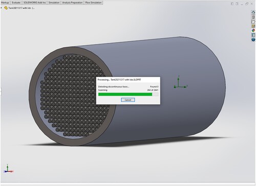
Figure 11. Adding the new heat transfer fluid, Therminol SP (Eastman Chemical Company Citation2023).
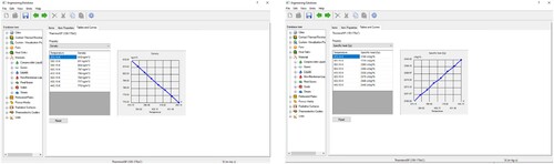
Figure 12. Selection of appropriate computational domain for the 3-D simulation
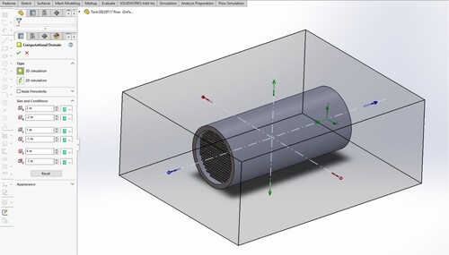
Figure 13. Stainless steel material applied in the tank envelope and the cylinders.