?Mathematical formulae have been encoded as MathML and are displayed in this HTML version using MathJax in order to improve their display. Uncheck the box to turn MathJax off. This feature requires Javascript. Click on a formula to zoom.
ABSTRACT
Thermal systems, including those utilising solar energy and waste heat recovery, often have a mismatch between the energy supply and demand. It is crucial to implement a form of Thermal Energy Storage (TES) to effectively utilise the energy source. This study evaluates the thermal performance of a packed bed Latent Heat Thermal Energy Storage (LHTES) unit that is incorporated with a solar flat plate collector. The results show that the time required to charge the tank is reduced by 7% when the porosity is increased from 0.49 to 0.61, and also when the flow rate is raised from 2 to 4 kg/min, the charging time decreases by 2.5%. Additionally, studies were done to investigate the performances of different kinds of paraffin (RT30, RT28HC, WAX, RT58, and P56-58), and compare the heat capacities of each TES tank which resulted in the RT58 TES tank having the highest heat capacity.
Abbreviations: BC: boundary conditions; HTF: heat transfer fluid; LHS: latent heat storage; LHTES: latent heat thermal energy storage; PCM: phase change material; SHS: sensible heat storage; TES: thermal energy storage
1. Introduction
Scientists worldwide are actively searching for innovative and sustainable energy sources to lower the amount of carbon emissions from the burning of fossil fuels, especially in situations where low-temperature applications are concerned.
Solar energy offers immense potential for building heating and cooling, as well as producing hot water for home and industrial use, such as cooking, warming greenhouses for agricultural crops, etc. (Kylili and Fokaides Citation2017). Nevertheless, solar energy is erratic, impulsive, and only accessible in daylight. Therefore, an efficient amount of TES is required where a vast amount of heat is collected and stored for later use during the night. Any energy storage technology's primary goal is to correct a temporal mismatch between the supply and demand for energy (Steinmann Citation2022). This balance is necessary in all electricity grids to maintain a stable and safe supply. Energy storage can balance out fluctuations in demand and supply by storing excess electricity for various periods of time, from quick storage of just a few seconds to longer storage over the course of days (European Commission Citationn.d).
In TES, the energy stored is transferred to the storage medium where it changes into an internal energy which can happen in the form of sensible heat or latent heat, or a combination of both (Sharma and Sagara Citation2005).
Paraffins are a common type of PCM used in TES systems due to their high latent heat of fusion and good thermal stability (Rathore and Shukla Citation2021). However, different types of paraffins can have different thermo-physical properties that may affect their performance in TES systems. In this study, the objective was to investigate the performance of five different types of paraffins in TES systems using simulations in COMSOL Multiphysics. This was achieved by comparing the performance of these paraffins, to determine which paraffin would be the most suitable for use in TES systems for low-temperature applications.
In addition, this study investigates how changes in porosity and the HTF flow rate can impact the performance of the TES system. The porosity of the packed bed in the TES system represents the fraction of the total volume that is occupied by the PCM, while the HTF flow rate represents the rate at which heat is transferred from the solar collector to the TES system. By studying the effects of these parameters on the TES system’s performance, optimisation of the system’s design can be achieved to improve its efficiency.
Many studies have been done on the performance of latent heat storage units (Pu et al. Citation2020). In the recent years, simulation tools and software have been gradually used to help in these. Computational fluid dynamics became an essential tool for the storage design as well as for analysing various working conditions. Simulations are especially helpful in heat transfer and temperature distribution analysis.
The novelty of this study lies in its systematic evaluation of a packed bed Latent Heat Thermal Energy Storage (LHTES) unit, considering the impact of porosity, flow rate, and paraffin material types. By addressing the challenges of thermal energy storage and providing specific insights into the LHTES system's thermal performance, the study offers valuable information for researchers, engineers, and policymakers working on sustainable energy storage and utilisation solutions.
1.1. Aim
This study aims to:
Explore latent heat storage systems and the utilisation of PCM materials.
Model a packed-bed storage tank unit integrated with solar water heating system, containing encapsulated PCM in spherical capsules, surrounded by SHS material.
Simulate different types of paraffins and study their performances.
Investigate the effect of HTF flow rate and porosity on the performance of the TES system.
Investigate and show the evolution of the PCM and HTF temperatures.
Determine which paraffin yields to highest capacity among the simulated TES tanks.
2. Theoretical background – literature review
Energy storage systems have long been praised for their capacity to decouple energy supply from energy demand, a critical trait that provides substantial flexibility in fuel and primary energy source selection. For thousands of years, flywheels have been employed in pottery production and early societies and cultures have long stored thermal energy in water and rocks for later use with no new advancements to be made on the practised methods until the onset of the Industrial Revolution (McLarnon and Cairns Citation1989). However, the demand for energy storage has risen as our society has come to depend more and more on easy and effortless access to affordable, clean energy.
According to Jouhara et al. (Citation2020) and Koohi-Fayegh and Rosen (Citation2020) energy storage can be classified into several categories, such as thermal energy storage, electrochemical energy storage, thermochemical energy storage, pumped hydro and magnetic energy storage, flywheel energy storage, compressed air energy storage, chemical and hydrogen energy storage.
2.1. Thermal energy storage
TES systems are used to conserve energy, enhancing the performance of energy systems by aligning energy supply with demand through the use of energy storage methods (Gil et al. Citation2010). This can lead to cost savings, a reduction in emissions, and an overall increase in efficiency (Arce et al. Citation2011).
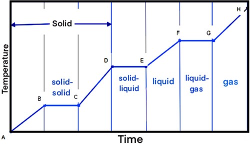
TES systems can store heat or cold to be used later, at different conditions such as temperature, place, or power (Cabeza et al. Citation2015). TES systems can be designed for SHS or LHS, or a combination of both. SHS involves increasing the temperature of the storage material as energy is stored, while LHS utilises the energy stored during a substance's change in phase. When heat is added to a substance, it causes an increase in internal energy, which results in a rise in the temperature (sensible heating) or a change in phase (latent heating). This is shown in . Starting from an initial solid state at point A, the addition of heat to the substance initially results in sensible heating of the solid (A–B) followed by an alteration in crystalline structure (B–C) that results in a solid–solid phase change, further sensible heating of the solid (C–D), a solid–liquid phase change (D–E), sensible heating of the liquid (E–F), a liquid–gas phase change (F–G), and sensible heating of the gas (G–H) (Regin, Solanki, and Saini Citation2008).
Figure 1. Temperature–time diagram for the heating of a substance (Regin, Solanki, and Saini Citation2008).
The total amount of energy stored can be written as,
(1)
(1) where
is the mass of material,
is the specific heat of material in solid phase,
is the specific heat of material in liquid phase,
is the specific heat of material in gas phase,
is the latent heat of solid–solid phase change,
is the latent heat of solid–liquid phase change, and
is the latent heat of liquid–gas phase change.
2.1.1. Sensible heat storage
The most typical way to store heat is SHS. This type of heat storage technique is the simplest and most straightforward (Jouhara et al. Citation2020). It has traditionally been used to store heat (Koohi-Fayegh and Rosen Citation2020). Sensible thermal storage is produced by changing the temperature of a medium for storing heat, such as water, oil, or ceramic materials. The amount of heat that can be held depends on the material's specific heat capacity (Mehling and Cabeza Citation2008). In this case, the temperature changes in a linear manner according to the amount of stored heat. Low energy density and thermal energy loss at all temperatures are two drawbacks of this type of energy storage (Jouhara et al. Citation2020).
Heat energy stored in the medium is absorbed and released through radiation, conduction, and convection and is presented by the formula below (Rathore and Shukla Citation2019).
(2)
(2) Here,
is the quantity of the material’s heat storage,
is the mass of storage material,
is the specific heat, and
is the change in the temperature.
Some common materials used in sensible heat TES systems are presented in (Cabeza et al. Citation2015).
Table 1. Typical materials used in sensible heat TES systems (Cabeza et al. Citation2015).
2.1.2. Latent heat storage
LHS is a fairly recent field of study and was first explored by Dr. Telkes in the 1940s though until the energy crisis of the late 1970s and early 1980s, it did not receive significant attention (Sharma and Sagara Citation2005).
LHS systems use the reversible enthalpy change Δh pc of a material that undergoes a phase change to store or release energy. Fundamental to LHS is the high energy density near the phase change temperature of the storage material (Steinmann Citation2022). The most relevant materials that are used are: molten salt, paraffin wax and water/ice (Elias and Stathopoulos Citation2019).
A substance may store heat by changing phases (solid–liquid, liquid-to-vapour, and solid-to-gas) at a nearly constant temperature through latent heat energy storage (Rathore and Shukla Citation2019). Evaporation, condensation, crystallisation, and melting are examples of phase shifts that can occur in either the solid or liquid phase without changing the aggregation state (Jouhara et al. Citation2020). Depending on the qualities of the chosen material, this method can store a significant quantity of heat or cold (Jouhara et al. Citation2020). As a result, the PCM energy density storage capacity rises throughout a narrow temperature range (Rathore and Shukla Citation2019).
This makes PCM systems an attractive solution for applications where heat transfer within a narrow temperature range is required (Abedin and Rosen Citation2011).
(3)
(3) Here,
is the quantity of the material’s heat storage,
is the mass of storage material, and
is the phase change enthalpy.
Some common materials used in latent heat TES systems are presented in (Cabeza et al. Citation2015).
Table 2. Typical materials used in latent heat TES storage (Cabeza et al. Citation2015).
2.2. Latent heat storage system elements
A LHTES unit consists of three main parts (Regin, Solanki, and Saini Citation2008):
A fitting PCM.
A PCM container.
A heat exchange surface is required for transferring the heat from heat source to PCM and from PCM to the heat sink.
2.2.1. PCM materials
PCM was initially used in British trains against cold (Stritih Citation2003). The first reported utilisation of PCM in literature was for temperature regulation in buildings, specifically for heating and cooling, by Telkes (Citation1975). Telkes (Citation1978) first proposed the concept of incorporating PCMs in walls, commonly referred to as Trombe walls.
The phase change is a process of going from one physical state to another. The three basic phases of matter: solid, liquid, and gas are known but others are thought to exist, including crystalline, colloid, glassy, amorphous, and plasma phases (Kiron Citation2012). Materials that undergo this process are known as PCMs.
Even though many ways of TES have been established, PCMs are substances that can absorb, amass, and release a significant amount of energy per unit of mass in the phase’s transition temperature range, thus being so common and popular and utilised in several TES applications (Jouhara et al. Citation2020).
Utilising PCM in solar energy or heat recovery systems can result in energy savings. The effective utilisation of energy, managing the imbalance among supply and demand, and improving the effectiveness of energy systems are all made possible by LHTES based on PCM.
As the material’s phase changes from solid to liquid, the chemical bonds inside the PCM disintegrate as the source temperature increases. As a result, the PCM absorbs heat because the phase change is an endothermic reaction (Sharma and Sagara Citation2005). When the phase change temperature is attained, the material starts melting. After that, the temperature remains constant until the melting is complete. The heat stored during this process is called latent heat.
PCMs’ main advantages:
The ability to store large amounts of heat with minor temperature changes, as a result has a high storage density.
Smoother temperature variations.
Cheaper as they require smaller weight and volume (Jouhara et al. Citation2020).
Can be used in a wide temperature range (Sharma and Sagara Citation2005).
According to (Buddhi and Sawhney Citation1994; Garg, Mullick, and Bhargava Citation1985; Hale, Hoover, and O’Neill Citation1971; Mehling and Cabeza Citation2008), desirable thermo-physical, kinetic, chemical, and economical properties should be achieved for a PCM to be utilised when designing a TES unit. The required properties are listed below.
Thermo-physical properties:
Desired temperature range for melting.
High latent heat of fusion per unit volume to reduce the required container size for a given amount of energy.
High melting enthalpy for a high latent heat storage capacity.
High specific heat for sensible temperature changes.
High thermal conductivity in both solid and liquid phases to aid in both charging and discharging energy in storage systems.
Minimal volume changes during phase transformation and low vapour pressure at operating temperatures to minimise containment issues.
PCM has congruent melting for a consistent storage capacity with each freezing/melting cycle.
Minimal supercooling.
Kinetic properties:
Adequate rate of crystallisation, ensuring the unit meets the demands of heat recovery from the storage system.
Rapid nucleation rate to prevent supercooling of the liquid phase.
Chemical properties:
Complete and reversible freezing and melting cycles.
Chemical stability.
Non-corrosive and compatible to the materials used in construction.
No degradation after multiple freezing and melting cycles.
Non-toxic, non-flammable, and non-explosive materials for safety and minimal impact on the environment.
Economical properties:
Low cost, easily available.
Environmentally friendly and economically sustainable through the ability to be recycled.
The primary factor to consider when selecting a PCM material is the melting point (Jouhara et al. Citation2020; Reyes et al. Citation2020). When deciding on a PCM material, it is important to take into account the temperature range in which it will be used. The melting point of the material should be lower than the temperature of the heat source and higher than the surrounding environment (Reyes et al. Citation2020).
In reality, no available PCM fully satisfies all requirements to date, but each has its own pros and cons to take into consideration for every application.
2.2.1.1. Classification of PCMs
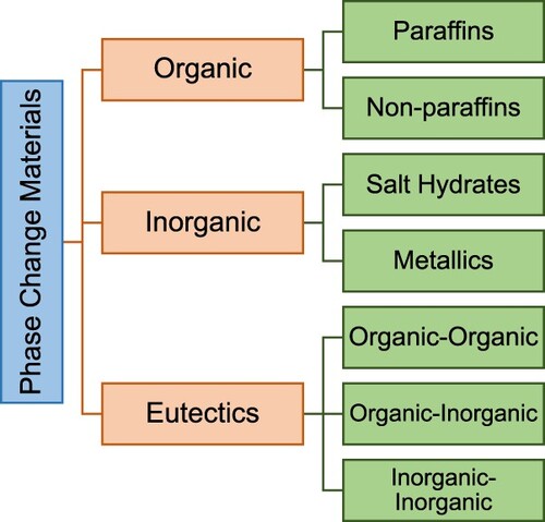
PCMs separate into three groups, based on phase change state: solid–solid, solid–liquid, and liquid–gas. Amongst the solid–liquid PCMs are most fit for thermal energy storage. The solid–liquid PCMs include organic PCMs, inorganic PCMs, and eutectics (Kiron Citation2012). Organics include mainly paraffins or non-paraffins, inorganics include salt hydrates and metallics and eutectic include mixed PCMs of organic and inorganics (Kylili and Fokaides Citation2016; Fokaides, Kylili, and Kalogirou Citation2015).
The following classification tree shown in displays the groupings for typically used PCMs.
Figure 2. Classification of PCMs.
Owing to their extremely diverse chemical and thermal behaviour, the features of the subgroups that influence the design of LHTES systems for using PCMs from that subgroup are covered in detail below.
2.2.1.1.1. Organics PCM
Natural materials are referred to as organic materials. They are categorised and described as paraffin and non-paraffins (Magendran et al. Citation2019). Organic materials have congruent melting which gives them the ability to repeatedly melt and freeze without phase separation, which would reduce their latent heat of fusion. Self-nucleation causes them to solidify; to form crystals with little to no supercooling, and with minimal corrosivity (Sharma et al. Citation2009).
2.2.1.1.1.1. Paraffins
The normal paraffins, which are hydrocarbons with the chemical formula CnH2n + 2, have similar characteristics. Those with shorter hydrocarbon chains are liquids, while those with longer chains are waxy solids. As the length of the hydrocarbon chain increases, the melting temperature and heat of fusion also increases (Sharma and Sagara Citation2005).
Paraffin has been widely used in energy storage systems due to its advantageous properties such as a high heat of fusion, fluctuating phase change temperature, high phase change enthalpy, zero supercooling characteristics, low vapour pressure, constant conductivity cyclic stability (Reyes et al. Citation2020). Additionally, the different melting points of paraffin make it suitable for boosting indoor thermal performance by incorporating it into double-glazed units, thus dropping the energy demand of the building (Jouhara et al. Citation2020).
Paraffins exhibit little volume changes while melting, are chemically inert and stable below 500°C, and have low vapour pressure when in the melt state. The freeze-melt cycle of system-using paraffins is typically relatively long due to these characteristics of the paraffins. Technical grade paraffins, which are mainly paraffin mixes and are not fully refined oils, are listed by their thermal properties in (Sharma et al. Citation2009).
Table 3. Physical properties of some paraffins (Sharma et al. Citation2009).
2.2.1.1.1.2. Non-paraffins
The PCMs with the greatest number and widest range of properties are the non-paraffin organics. As opposed to paraffins, which have remarkably comparable properties, each of these materials will have unique characteristics. These materials are flammable and should not be exposed to excessively high temperature, flames, or oxidising agents (Sharma et al. Citation2009). Few examples of non-paraffin’s are showed in .
Table 4. Physical properties of some non-paraffins (Sharma et al. Citation2009).
2.2.1.1.2. Inorganics PCM
Metallics and salt hydrates are additional categories for inorganic materials. When compared to organic compounds, inorganic compounds have lower volume costs, more latent heat per unit mass, and are non-flammable (Tyagi and Buddhi Citation2007). They experience decomposition and supercooling, though, which can further modify their phase-change properties (Sharma et al. Citation2009).
2.2.1.1.2.1. Salt hydrates
Salt hydrated are alloys of inorganic salts and water that when combined form a crystalline solid with general formula (Sharma et al. Citation2009; Wong-Pinto, Milian, and Ushak Citation2020). The bonds formed are usually ion-dipole bonds or hydrogen bonds. The water molecules are located and oriented in the structure, and while in some structures the water is closer to the anion, in others to the cation of the salt (Hyun et al. Citation2014). The use of salt hydrates in TES systems has drawn a lot of research. Salt hydrates are attractive for TES due to their high latent heat of fusion, high thermal conductivity, and minimal volume changes during phase changes. However, they can be slightly toxic and not always compatible with plastics, making them less suitable for transportation and storage (Wong-Pinto, Milian, and Ushak Citation2020). The low thermal conductivity, corrosivity, non-negligible phase change associated volume increase, and significant subcooling are only a few of the drawbacks that limit the use of salts (Cárdenas and León Citation2013).
2.2.1.1.2.2. Metallics
Metallics PCMs have not been actively considered for LHS systems due to their weight and cost (Costa and Kenisarin Citation2022). However, since they have a high latent heat of fusion per volume unit, they are good candidates when volume is a priority and can compete with salts (Cárdenas and León Citation2013). The main advantage of metallics PCMs is their high thermal conductivity, which eliminates the design of thermal energy storage, reducing the need for heat transfer improvements methods (Costa and Kenisarin Citation2022).
2.2.1.1.3. Eutectics
A minimum-melting composition of two or more components is known as a eutectic, and during crystallisation, each of these components melts and freezes concurrently to form a mixture of the component crystals (Tyagi and Buddhi Citation2007). Eutectic materials almost never segregate during melting or freezing because they freeze to an intimate mixture of crystals, minimising the chance of the components separating. Both components simultaneously liquefy when melted, making separation unlikely (Sharma et al. Citation2009). A further challenge in evaluating eutectics salts as PCMs is the fairly large heat flux that is required. Heat transfer is decreased since eutectic salts have a comparatively low thermal conductivity. However, due to the large variety of thermal conductivities, it is important to consider how it may affect system costs (Raud et al. Citation2017).
2.2.2. Containers
When designing a latent heat storage system, once the PCM is selected, the next most crucial factors to consider are (Agyenim et al. Citation2010):
PCM container’s geometry.
The container’s required thermal and geometric parameters for a given amount of PCM.
Each of these factors has a direct influence on the heat transfer characteristics in the PCM and finally affects the performance and the melt time of the PCM storage unit. Therefore, successful use of PCM and HTF depends on developing means of containment.
The size and shape of the PCM container must agree with the melting time of the PCM and the daily insolation at a given location if the source of energy is a solar collector. This is to the guarantee long-lasting thermal performance of any PCM system.
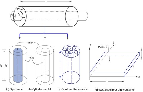
Typical geometries of containers that PCMs are placed in are rectangular containers, cylindrical containers, or long thin heat pipes. gives the schematics of the cylindrical and rectangular containers.
Figure 3. Typical geometries of PCM containers (Agyenim et al. Citation2010).
PCM containment should (Regin, Solanki, and Saini Citation2008):
Facilitate efficient heat transfer by providing a suitable surface area.
Function as a protective shield to prevent the PCM from being affected by external factors.
Ensure structural stability and ease of handling.
Ensure the necessary strength, flexibility, resistance to corrosion, and thermal stability are met.
shows the different containment schematics used in LHTES systems.
Figure 4. Different containment schematics used in LHTS systems (Regin, Solanki, and Saini Citation2008): (a) flat plate; (b) shell and tube with internal flow; (c) shell and tube with parallel flow; (d) shell and tube with cross flow; (e) sphere packed bed.
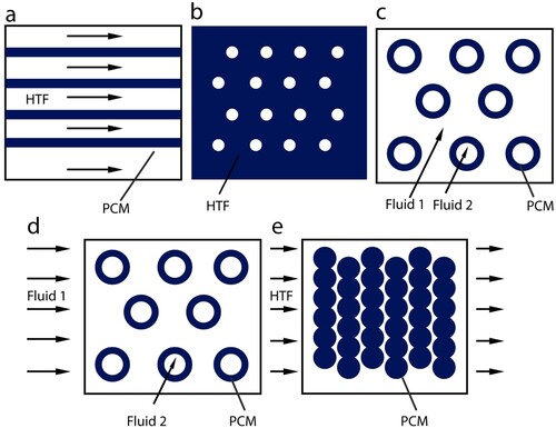
Types of containment examined are bulk storage in tank heat exchangers, macroencapsulation, and microencapsulation.
2.2.2.1. Bulk storage
Bulk storage encases PCM in large tanks (Whiffen and Riffat Citation2013). The main unique trait of PCM bulk systems is the demand for a higher heat transfer compared to that found in non-PCM tanks due to the PCM’s heat storage density being higher than other storage media (Regin, Solanki, and Saini Citation2008).
A cost-effective method of energy storage that involves minimal processing of materials but has faced challenges due to low thermal conductivity resulting in inconsistent performance. Whiffen and Riffat (Citation2013) have investigated ways to enhance heat transfer, through agitation and increasing the surface area.
2.2.2.2. Macroencapsulation
The widest way used for PCM containment is macroencapsulation, where a substantial amount of PCM is encapsulated in an isolated unit such as tubes, spheres, panels, or other receptacle. These types of containers can be used directly as a means of heat transfer, or they can be integrated into building products (Cabeza et al. Citation2011). The mass of PCM per unit may range from few grams to a kilogram and encapsulated in containers of normally greater than 1 cm diameter (Regin, Solanki, and Saini Citation2008).
Besides holding the liquid PCM and averting changes of its composition through interaction with the environment, macro encapsulation also (Cabeza et al. Citation2011; Regin, Solanki, and Saini Citation2008):
improves material compatibility with the surrounding, through building a barrier.
improves handling of the PCM in a production.
reduces external volume changes.
minimises phase separations.
improves the heat transfer rate.
provides a self-supporting structure for the PCM.
These macroencapsulation units prevent corrosion, allowing for the encapsulation of inorganic PCMs. Additionally, insufficient heat transfer across the confined PCM results in edge solidification, which limits performance (Whiffen and Riffat Citation2013). As a result, the most economical options for containers are containers made of plastic such as high-density and low-density polyethylene bottles, and metal cans made of mild steel and tin plating (Regin, Solanki, and Saini Citation2008).
As demonstrated by the abundance and calibre of research, the macrocapsule is the most widely used containment method for PCMs. By carefully choosing the geometry and material of the capsule, it can be utilised to meet a wide range of energy storage needs.
2.2.2.3. Microencapsulation
Microencapsulation refers to the technique in which a large amount of small, spherical, or rod-shaped particles, usually of a few microns in diameter, are enclosed in a thin, high molecular weight sealed membrane. If the membrane encapsulating the PCM does not have high thermal conductivity, the system suffers from a low heat transfer rate (Regin, Solanki, and Saini Citation2008). Microencapsulation serves the same purpose as mentioned above for macro encapsulation, but also (Cabeza et al. Citation2011):
increase heat transfer to the surrounding due to its high surface to the volume ratio
improves cycling stability since phase separation is limited to microscopic distances.
Due to the high surface area to volume ratio, most modern applications of PCM favour microencapsulation, minimising the effects of poor thermal conductivity. The thermal conductivity of the shell has a considerable impact on the total thermal conductivity of the capsules due to their tiny size. Internal volume variations in microencapsulated PCM are endured by the shell and avoid bulk volume change (Whiffen and Riffat Citation2013).
Although, at the moment, the cost of using microencapsulation is relatively high in comparison to other methods and is typically only used in specific applications related to thermal control.
2.3. PCM beds for thermal storage
2.3.1. Schematics of PCM beds
A packed-bed LHTES system consists of four main components: the TES tank, PCM capsules (e.g. Spherical), HTF, and distributor, as shown in (a).
Figure 5. (a) Schematic of a PCM bed TES tank with spherical capsules, (b) HTF flow around PCM (He et al. Citation2022).
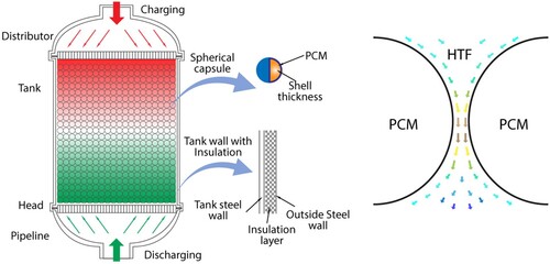
In the packed bed, there are a lot of heat storage capsules amassed together. HTF flows and transfers heat between the voids of capsules absorbing, storing, and releasing the thermal energy that exists between PCMs and HTF. In order to provide uniform fluid flow through the cross-section of the packed-bed region, the distributor is positioned at both ends of the tank. Different PCM types and encapsulation technologies are taken into consideration to determine the precise operating parameters in accordance with the application target, thermal storage capacity, and economy (He et al. Citation2022).
Finding a practical and cost-effective way to achieve the heat transfer required to alternate between freezing and melting the storage medium in a LHTES system is crucial (Regin, Solanki, and Saini Citation2008).
It is possible to think of the packed-bed LHTES system with spherical capsules as a continuous porous media. In order to generate a stable and uneven solid framework that is equivalent to porous media macroscopically, spherical capsules support and squeeze one another. As shown in (b), HTF circulates through the spaces created by the pores in the capsules and transfers heat to the PCM (He et al. Citation2022).
When designing a storage unit containing PCM, the main factors to be considered are (He et al. Citation2022):
temperature target and cycle time
type and size of PCM particles
the void fraction within the bed
the thermophysical properties of PCMs
the thermophysical and flow properties of HTF
the thermal load
configuration of the storage bed
design parameters of encapsulation method (e.g. spherical capsules)
Effective heat transfer between the HTF and the capsules in the bed is necessary for improved operation of a packed bed. There are several factors that can influence and impact the performance of a packed-bed TES unit, which can be separated into three classes (He et al. Citation2022; Regin, Solanki, and Saini Citation2008):
The ones related with the bed construction and geometry of the container.
The ones that determine the traits of the fluid such as its properties and flow rate.
The ones that are related to the bed material's transient response, such as the bed's initial thermal state, the fluid's inlet temperature, the physical and thermal properties of the bed material, and the coefficient of convective heat transfer.
2.3.2. Operation modes
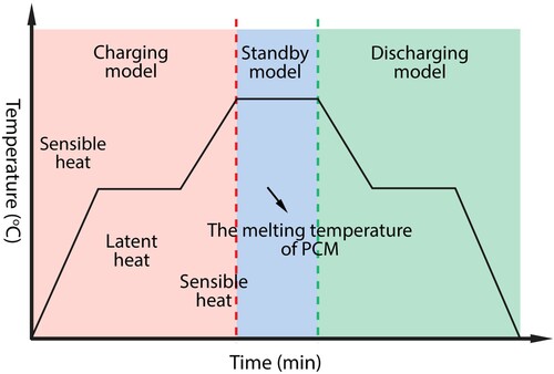
The heat is transferred to or from the HTF as the HTF flows through the voids in the bed. As shown in , the system functions in three modes (He et al. Citation2022):
Charging mode: Firstly, the hot HTF carrying energy from the source is circulated through the tank. The encapsulated PCM absorbs latent heat and melts. SHS is carried out first, and once it reaches the melting temperature, the latent heat is charged. If the starting temperature of HTF is higher than the melting temperature of PCM, thermal energy is continuously being charged as sensible heat after the PCM has melted entirely.
Discharging mode: This mode occurs when the cold HTF’s temperature is lower than the temperature in the tank and is circulated through the tank, causing the encapsulated PCM to freeze. The heated fluid is then utilised to fulfil the demand either directly or through a heat exchanger. The PCM liquid phase ratio changes with time. After PCM has fully solidified, the system is also discharged in the form of sensible heat.
Standby mode: The system switches to standby mode when the tank is fully charged or discharged or when there is no efficient heat exchange. This is the change from charging to discharging mode.
Figure 6. The TES system operation modes (He et al. Citation2022).
2.4. Economic analysis
It is important to consider the cost of LHTES systems when evaluating their feasibility. Many current cost analyses for LHTES systems rely on experimental or estimated values for the PCMs used in these systems (Nithyanandam and Pitchumani, Citation2014a; Jacob et al. Citation2014). However, such data is only available for a limited number of PCMs, which means that cost-effective options may be missed. The method described below can be used to compare the theoretical costs of encapsulated LHTES systems using predicted PCM properties. For more information on cost analysis of other types of LHTES systems, please refer to the provided reference (Nithyanandam and Pitchumani, Citation2014b).
Three key expenses make up the price of an encapsulated LHTES: the encapsulation cost, the tank cost, and the storage medium cost. The installation cost is thought to be twice as large as the direct cost. The price of encapsulation can be based on prices calculated by Nithyanandam and Pitchumani (Citation2014b) based on the size of the capsule and a fluidised bed coating process. By modifying the following equation to account for the size of the capsule and the cost of the capsule material, we are able to increase the validity of Nithyanandam's estimation and conduct a more comprehensive cost analysis for different shell materials.
(4)
(4) where
is the cost of encapsulation,
is the mass of the total required shell material,
is the cost of encapsulation material,
is the capsule radius,
is the processing cost, and
is the mass of the PCM to be encapsulated.
The estimation of the cost of the tank is based on previous research (Herrmann, Kelly, and Price Citation2004; Kelly and Kearney Citation2006; Nithyanandam and Pitchumani, Citation2014c) on the actual cost of storage tanks. The cost of the tank is broken into three main costs: the tank material, the insulation, and the foundation:
(5)
(5) where
is the density of the tank material,
is the height of the tank material,
is the radius of the tank material,
is the thickness of the storage tank,
is the cost of the tank material, and
and
are the cost of the foundations and insulation, respectively.
According to Jacob et al.'s (Citation2014) design methodology, the theoretical and measured PCM's storage tank size and material mass can be estimated. The storage material's cost is calculated by multiplying the PCM and HTF bulk prices by their respective mass. It is reasonable to assume that bulk prices can be used for large storage systems, but it's important to note that additional costs for transportation and further processing may also be incurred and are not considered in this analysis. Costs associated with various typical PCMs and HTFs can be found in Liu et al. (Citation2016) and Xu et al. (Citation2015).
In addition to the direct costs mentioned above, there are also indirect costs associated with LHTES systems that need to be considered. These costs include maintenance, operational expenses, and potential system modifications (Robak, Bergman, and Faghri Citation2011). Maintenance costs encompass regular inspections, repairs, and replacements of system components over its expected lifetime. Operational expenses involve the cost of energy required for the system's operation, such as electricity for pumps and controls. Furthermore, to accommodate changes in energy demand or improve system performance, modifications or upgrades might be necessary, leading to additional costs.
To obtain a comprehensive understanding of the economic viability of LHTES systems, a life-cycle cost analysis (LCCA) should be conducted. LCCA considers all the costs associated with a system throughout its entire life, from initial investment to decommissioning (Struhala and Ostrý Citation2022). It accounts for factors such as the system's expected lifespan, discount rates, and inflation to provide a more accurate picture of the system's long-term financial impact.
By including these indirect costs and performing a life-cycle cost analysis, researchers and policymakers can make well-informed decisions about the adoption and implementation of LHTES systems. It allows them to evaluate not only the initial investment but also the ongoing costs and benefits, leading to more sustainable and economically viable solutions for energy storage and management.
2.5. Experimental studies
A variety of experimental and numerical investigations were studied to further understand how different types of paraffin behave under different conditions. These would act as a reference when running the simulation and importing values for the parameters and properties of the TES unit.
2.5.1. Technical grade paraffin RT30
Due to their wide melting/solidification temperature ranges and comparatively large latent heat capacity, technical-grade paraffins have been widely used as heat storage materials. Additionally, they do not experience any subcooling during the solidification process and only experience a minor volume change throughout the phase change processes. They are neither toxic, corrosive, or chemically unstable and can be stored for a long time without harm (Trp Citation2005).
Anica Trp (Citation2005) conducted an experimental and computational analysis of heat transfer during the solidification and melting of technical grade paraffin in a shell-and-tube latent thermal energy storage system. Rubitherm RT 30, a technical grade paraffin, was used as the PCM in studies due to its appropriate thermophysical characteristics, widespread availability, and relatively low cost. The schematic of shell-and-tube unit used is shown in . The results offer a reliable estimate of the PCM melting and solidification processes, providing accurate guidelines for optimising a TES unit's performance and design.
Figure 7. Shell-and-tube unit (Trp Citation2005).
2.5.2. Paraffin RT28HC
In another experimental analysis done by Zeinelabdein, Omer, and Gan (Citation2018), paraffin produced by Rubitherm Gmbh was used once again called paraffin RT28HC. The performance of PCM charging and discharging was examined, under various inlet operating conditions for various arrangements of PCM modules with different air flow channels. The proposed TES unit had 16 modules, which were arranged in eight parallel rows of two modules each. In order to fit the full arrangement of PCM storage modules, a rectangular enclosure made of aluminium measuring 1.25 m (L) × 0.31 m (W) × 0.26 m (H) was created. shows the positioning of the PCM modules inside the main container.
Figure 8. Module arrangement of PCM containment (Zeinelabdein, Omer, and Gan Citation2018).
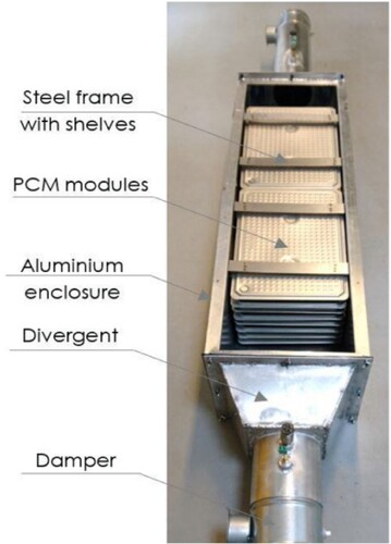
The study concluded that the optimisation of the distance between the PCM panels plays a crucial role in enhancing the TES system performance. In addition, a slower melting rate can be achieved during the discharging process with wider air channels.
2.5.2.1. Paraffin wax
Another experimental and numerical investigation was done by Kibria et al. (Citation2014), using paraffin wax, suitable for the domestic hot water system. Paraffin wax is widely used for its excellent heat storage density and ability to melt or solidify with little to no sub-cooling as well as for being cheap and non-reactive with most chemical reagents. To analyse the storage unit's heat transfer behaviour in both cycles with various flow parameters and system dimensions, a parametric study is conducted. It is discovered that tube thickness is not a crucial factor for enhancing the storage unit's performance. Consequently, tube radius has a greater effect on the storage unit's operational time and outlet temperature. It may be said that the current study may provide suggestions for designing an optimised LHTES system with PCM.
2.5.2.2. Paraffin RT 58
In the work of Liu, Yao, and Wu (Citation2013), a shell-and-tube type LHTES unit is used with a numerical model created for the PCM embedded in metal foam. Based on the numerical predictions, parametric research is conducted to analyse the effects of influencing factors on the thermal performance of the storage unit. From their experiment, they concluded that the phase change heat transfer can be improved by more than seven times when compared to the outcomes of the pure PCM and the in-let conditions played a significant role in their performance results.
2.5.2.3. Paraffin of P56-58 (MERCK)
In another experimental study done by Avci and Yazici (Citation2013), solidification and melting characteristics of paraffin of P56-58 produced by MERCK have been examined.
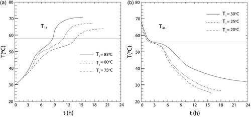
A horizontal shell-in-tube thermal energy storage unit has been taken into consideration. It has been discovered that melting behaviour is significantly different for locations in the upper area as opposed to the lower section. Natural convection currents cause the molten PCM to rise to the upper section of the storage unit. Because the melt area outspreads radially upward, the temperature field is radially asymmetric. Thus, the points in the upper section reach the melting temperatures before those in the lower section. Convection has initially been shown to be effective in transferring heat for the solidification behaviour, which is thereafter reduced by conduction. As anticipated, it is discovered that the HTF inlet temperature accelerates the phase change process within the PCM either by increasing (charging) or decreasing (discharging) it. The asymmetrical behaviour observed may result in new pioneering designs. (a and b) show the effect of the inlet temperature on the total melting and solidification time.
Figure 9. Effect of inlet temperature on the (a) total melting time and (b) solidification time (Avci and Yazici Citation2013).
3. Methodology
The purpose of this dissertation is to model the flow through a TES tank and investigate its performance using different types of paraffins.
3.1. Simulation tool
The implementation of this study is done in COMSOL Multiphysics Simulation Software which is a simulation platform that provides fully coupled multiphysics and single-physics modelling capabilities, able to simulate designs, devices, and processes in all fields of engineering, manufacturing, and scientific research. It is particularly useful for studying systems that involve multiple coupled physics phenomena, such as thermodynamics, electromagnetics, and fluid dynamics. The software includes a wide range of predefined models and simulation tools, as well as the ability to build custom models using specialised numerical methods. The software utilises advanced algorithms and finite element analysis to accurately simulate and predict the behaviour of systems in various fields such as electrical, mechanical, fluid, and chemical engineering. The software is widely used in research and industry and has a user-friendly interface.
With COMSOL Multiphysics, users can predict system behaviour, optimise designs, and validate performance, all within a single integrated software environment. Overall, COMSOL Multiphysics is a powerful tool for understanding and predicting the behaviour of complex physical systems (COMSOL).
3.2. Model definition
Due to its relatively cheap nature, dependability, and commercial availability for a wide range of melting temperatures, paraffin is an appropriate PCM to include and study the influence of latent heat.
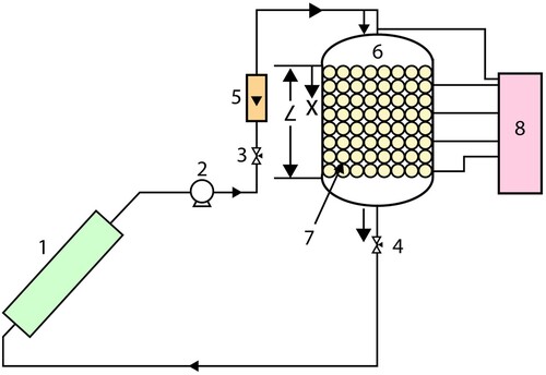
The modelling of the storage unit is inspired by the experiment found in Nallusamy, Sampath, and Velraj (Citation2006). The experimental setup illustrated in includes a solar flat plate collector (1), a circulating pump (2), two flow control valves (3,4), a flow meter (5), an insulated cylindrical TES tank (6) with spherical capsules containing PCM (7), and a temperature indicator (8).
Figure 10. Schematic of experimental setup (Nallusamy, Sampath, and Velraj Citation2006).
3.2.1. Parameters
In this system, the initial temperature is set to 25°C and the porosity of the bed is ϵp = 0.49. Water flows inside the TES tank with a flow rate of Vin = 2 kg/min, and it is continuously heated by a solar collector that delivers a power of Qu = 375 W. The tank is made of stainless steel and has dimensions of 0.36 m in diameter and 0.47 m in height, with a capacity of 48 L, capable of supplying hot water for a family of 5–6 people. The tank has two chambers, on top and bottom, and a flow distributor on the top to ensure the HTF has a uniform flow. The tank is also insulated with glass wool of thickness of 0.05 m. The PCM capsules have a diameter of 0.055 m and are made of high-density polyethylene with a wall thickness of 0.8 mm. There are 264 capsules in the tank, which are packed uniformly in eight layers and maintained by wire mesh. The capsules occupy 51% of the total volume of the tank, while the remaining volume is occupied by SHS material. Paraffin is used as the PCM, and water is used as both the SHS material and the HTF, with the PCM capsules in the TES tank being immersed in water. The specifications of the storage tank are also given in .
Table 5. Main outcomes for each material.
3.2.2. Geometry
The tank contains spherical capsules filled with paraffin, which have a diameter of 55 mm and are placed within a cylindrical container measuring 36 cm in diameter and 47 cm in height. The 2D geometry of the model is shown in .
Figure 11. 2D model geometry.
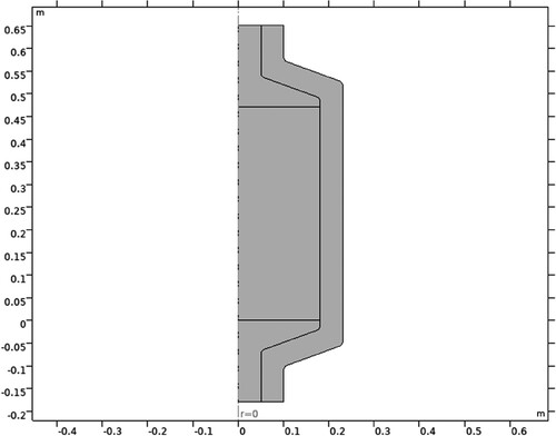
Only a section of the TES system was drawn as that was the only section necessary. Defeaturing is a powerful way to simplify the part/s under investigation, as it allows for an increase in ease of meshing, without decreasing the accuracy of the analysis. This was done to take advantage of the reflective symmetrical geometry of the part, by splitting the part in half along the line of symmetry. This led to a much simpler part with a much-reduced computational time, as the number of elements were significantly reduced. This allowed for a much more refined mesh and reduced the storage requirements for the analysis.
3.2.3. Boundary conditions
To increase the accuracy of the simulation regarding the real-world situation the part is used in, boundary conditions (BC) were utilised and applied to the model (COMSOL Documentation Citation2022).
3.2.3.1. Axial symmetry
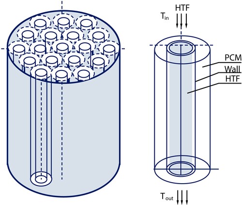
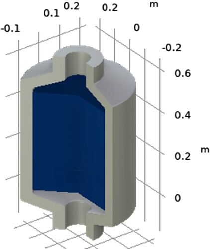
Axial symmetry BC applies frictionless supports on symmetric cut planes that constrain the motion normal to the cut plane. This BC was applied only to the surface area created when the part was split in half during defeaturing which translated to constraining that face from moving in the direction perpendicular to itself, but instead only to the 2 axis this plane lies on. The geometry of the 3D model is shown in .
Figure 12. 3D model geometry.
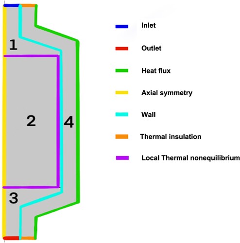
Additional boundaries and conditions that were set are:
Inlet
Outlet
Heat flux
Wall
Thermal insulation
Local thermal nonequilibrium
These are clearly shown in .
Figure 13. Boundary conditions.
3.2.3.2. Inlet condition
At the inlet condition, the option of Fully developed flow is added. In order to achieve a fully developed flow condition, the inlet boundary must be flat and additional contributions are added to the inflow boundary to guide the flow towards the solution. This approach considers the channel as an extended version of the inlet section, which is necessary for accurately modelling heat transfer with phase change.
3.2.3.3. Outlet condition
At the outlet condition, the Pressure option is selected. The normal stress at the inlet boundary is defined as the pressure and the tangential stress is set to zero. The reference pressure at the physics interface level is set to 0, meaning the value of the pressure at the boundary is the absolute pressure. The option of Suppress backflow is enabled by default. which adjusts the outlet pressure in order to prevent fluid from flowing back.
3.2.3.4. Heat flux
Convective heat flux is added as the flux type with a heat transfer coefficient (h) of 5 W/m2 K.
3.2.3.5. Wall
The Wall node includes a set of boundary conditions that describe how fluid interacts with stationary, moving, and leaking walls. The boundary condition at a wall is defined as No slip, meaning that the fluid velocity relative to the wall is zero. This is the default condition for modelling solid walls, and it applies to stationary walls, where the fluid velocity is equal to 0.
3.2.3.6. Thermal insulation
This node is the default boundary condition for all Heat Transfer interfaces. This BC means that there is no heat exchange across the boundary and the domain is well insulated. This condition is established by making sure that the temperature on one side of the boundary is equal to the temperature on the other side, resulting in a zero-temperature gradient and preventing any heat transfer. This boundary condition is typically applied to external boundaries, but it can also be manually applied to interior boundaries.
3.2.3.7. Local thermal nonequilibrium.
This node is automatically activated on all interior and exterior boundaries of the computational domain that are adjacent to areas where a Local thermal nonequilibrium porous medium type is applied. It indicates which boundaries are connected to regions where separate temperature values are being calculated.
3.2.4. Materials
The geometry is split into domains as shown in , where appropriate materials are selected for each as shown in . The selection of the Material type option determines how a material behaves and how its properties are interpreted when the mesh is deformed. In this case, the Solid option is chosen, which is appropriate for materials whose properties vary based on factors such as material orientation, material strain, and other variables assessed in a material reference configuration.
Table 6. Specification of the TES tank.
Other than water and the paraffin that are under investigation, glass wool is modelled for domain 4. Glass wool, also known as fibreglass, is a type of insulation that is highly effective and environmentally friendly. Its excellent thermal properties help to save energy and reduce environmental impact. It offers excellent thermal insulation because the small pockets of air in the glass wool minimise heat loss and help to maintain the desired temperature within the storage unit. Glass wool is also non-combustible, meaning it does not contribute to or spread fires. It is also easy to handle, store, transport, and install because it is compressed into rolls or sheets (Isover Citationn.d).
3.2.5. Meshing
Best simulations are those who use the simplest type of geometry and element type possible to provide results with significant enough accuracy, because as we increase the complexity of the elements, the computational time and resources rise as well. Assigning the layout of the elements that generate the part, is a process called meshing.
The storage unit was modelled with a physics-controlled mesh and the element size was set as Fine. The default physics-controlled mesh automatically takes into account that there are steep gradients for the velocity close to the walls. A fine mesh also resolves the thermal effects well. The mesh configuration is shown in and the complete mesh statistics are shown in .
Figure 14. Mesh configuration.
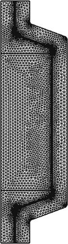
Table 7. Material selection.
3.2.6. Physics interface
The temperature difference between the inlet and outlet of the storage tank is given by the relation,
(6)
(6) Here,
is the density of water,
is the heat capacity of water, and
and
are the inlet and outlet temperatures.
The Ergun equation is used to calculate the pressure drop in a packed bed as a function of the velocity field u.
(7)
(7) Here,
is the viscosity of water,
is the density of water,
is the diameter of spheres, and
is the porosity.
The permeability of the packed bed is given by
(8)
(8) The Reynolds number can be approximate as
(9)
(9)
The maximum velocity in the bed, , was found to be around 6 mm/s, resulting in a Reynolds number of 600. This suggests that the flow field is not affected by temperature changes and a stationary field can be calculated, making the computation process more efficient.
The size of the capsules in relation to the storage tank indicates a significant temperature variation between the paraffin inside the capsules and the surrounding water flow, therefore a local thermal nonequilibrium approach is considered in this scenario.
The energy transferred from the paraffin-filled capsules to the water is modelled with a heat source.
(10)
(10) where
is the paraffin temperature,
is the water temperature, and
(W/(m3 K)) is the interstitial convective heat transfer coefficient, which for spherical capsules reads
(11)
(11)
The heat transfer within the capsules by convection is not considered in the model.
3.3. Development of studies
Several simulations are undertaken to investigate the impact of heat transfer during the phase change process, analysing the changes in temperature of both the paraffin and water. Each simulation is done by alternating various conditions and variables, both referencing previous studies and original ones. Results will be obtained and discussed to reach a conclusion.
As mentioned before, the initial temperature is set to 25°C and the bed’s porosity is ϵp = 0.49. Warm water flows through the tank with a flow rate of Vin = 2 kg/min, and during thermal charging it is continuously heated up by a solar collector which delivers a power of Qu = 375 W. These values are kept constant for each simulation, to lead to a fair investigation of the performance of the different tanks with the different paraffins.
The thermophysical properties of paraffin are alternated with each case study, with values obtained from the literature review and research, simulating as close as possible a real-life scenario. These include phase change temperature, latent heat, thermal conductivity, specific heat and density.
The values used for the simulation can be seen in .
Table 8. Mesh statistics.
In addition, crucial experimental parameters are porosity and HTF flow rate. Simulations were also done with different HTF flow rates (2, 4, 6 kg/min) and values for porosity (0.49, 0.61) to investigate the effect each has on the temperature of the PCM and HTF.
4. Results
This study examines and records the temperature changes of both the PCM and HTF in the TES unit for various types of paraffins during the charging process, as well as the distribution of phases after specific intervals of time. In addition, the results when altering the HTF flow rate and porosity are studied to investigate their effect on the TES tank.
4.1. Reference case – validation (Experiment vs Comsol)
(a and b) show the result of the experimental study of Nallusamy, Sampath, and Velraj (Citation2006).
Figure 15. (a) HTF Temperature, (b) PCM Temperature (Nallusamy, Sampath, and Velraj Citation2006).
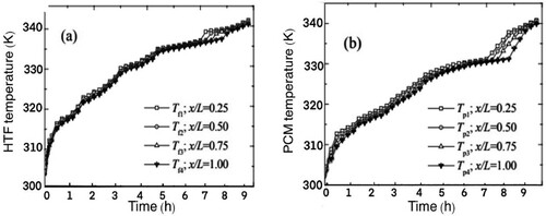
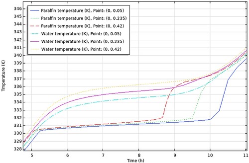
(a) shows the temperature change of the HTF inside the storage tank and (b) shows the temperature change of PCM, for a porosity of 0.49 and mass flow rate of 6 kg/min, at the different points of the storage unit from top to bottom.
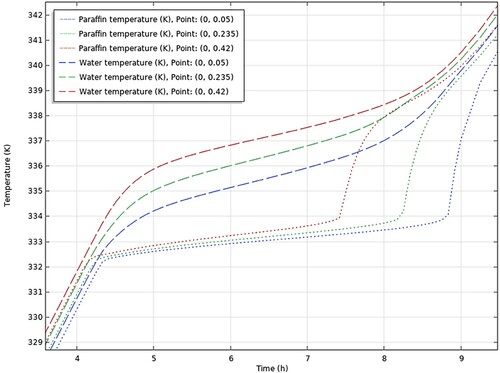
shows the temperature histories of the PCM and HTF at the three different coordinates as shown in the legend of the graph, which resulted from the simulations done in COMSOL.
Figure 16. COMSOL results. PCM and HTF temperature distribution.
4.2. Different studies
The conclusions drawn from the comprehensive analysis of paraffin types RT30, RT28HC, Wax, RT58, and P56-58 are displayed graphically in , respectively.
Figure 17. COMSOL results. PCM & HTF temperatures of TES tank using RT30.
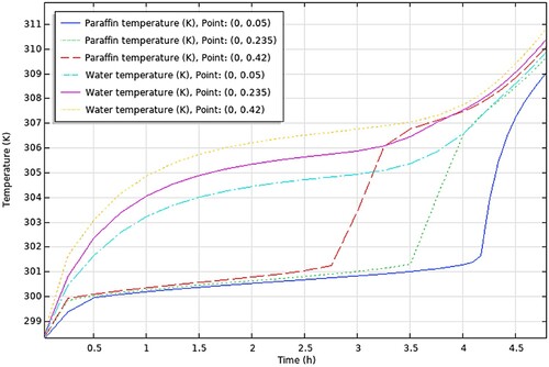
Figure 18. COMSOL results. PCM & HTF temperatures of TES tank using RT28HC.
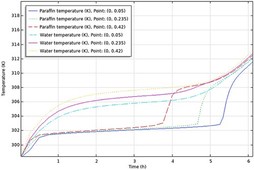
Figure 19. COMSOL results. PCM & HTF temperatures of TES tank using WAX.
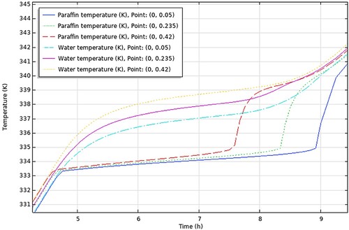
Figure 20. COMSOL results. PCM & HTF temperatures of TES tank using RT58.
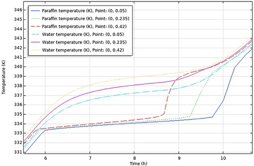
Figure 21. COMSOL results. PCM & HTF temperatures of TES tank using P56-58.
aThe figures encapsulate the distinct findings and notable performance traits of each paraffin type, contributing to a better understanding of their suitability and effectiveness in energy storage applications.
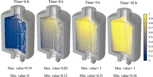
Additionally, the paraffin phase distribution for each paraffin is shown in the Appendix. These show at which hour each paraffin starts to melt and at which hour it is completely molten. It can be seen that at some points, the phase transition has not yet begun while it is already completed in the centre of the tank. This is due to the fact that, close to the walls, the flow velocity is insignificant.
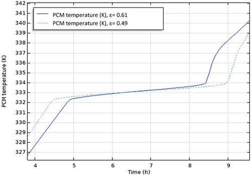
4.3. The effect of varying porosity
The outcome of the study when changing the value of the porosity is shown in .
Figure 22. COMSOL results. The effect of varying porosity.
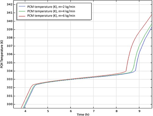
4.4. The effect of HTF flow
The outcome of the study when changing the value of the HTF flow is shown in .
Figure 23. COMSOL results. The effect of varying the HTF flow rate.
5. Discussion
During the charging process, the HTF is continuously distributed through the TES tank. The HTF transfers its energy to the PCM capsules. At the start of the charging process, the PCM inside the packed bed capsules is at a temperature of 25°C, which is lower than the melting temperature. Until the PCM reaches its melting temperature, the energy is stored as sensible heat. As the charging process goes on, and the melting of the PCM starts, the energy is stored at a constant temperature. Lastly, the PCM becomes superheated, and the energy is then stored as sensible heat in the liquid PCM. The charging process is continued until the PCM temperature reaches 70°C, due to the stop condition inserted in COMSOL to avoid unnecessary computational time and storage space.
5.1. Reference case
It is seen from (a) that the temperature of the HTF increases gradually until it reaches the temperature of 335 K where it remains almost constant at 337 K for around 3 h at which the PCM undergoes phase change. This period starts at approximately 5 h, same as in the COMSOL results shown in . The graph in (b) illustrates the gradual rise in PCM temperature at the beginning of the charging period, a stable temperature around 333 K during the phase change process, and a sudden sharp rise in temperature during the heating of the liquid PCM. The charging process is terminated when the PCM temperature reaches 70°C. As before, the phase change period starts at approximately 4.2 h for both experimental and COMSOL results.
Therefore, it can be observed that the experimental study agrees with the simulation as both studies yield the same results so it can be confirmed that the simulation is as accurate as it can be.
In addition, (a and b) show that there is little difference in temperature between different points in the storage tank (from top to bottom) throughout the sensible heating of solid PCM and the phase change period. This is true for the COMSOL results in as well. The gradual increase in temperature of the water in the storage tank is linked to the gradual increase of the HTF inlet temperature supplied by the solar collector. As a result, the PCM temperature increases as well in tandem with the HTF temperature.
5.2. Different studies
In this section, we will discuss the results of various studies and simulations that have been conducted using COMSOL on different types of paraffins for their use in TES systems. The focus of these simulations was on the PCM and HTF temperature histories within a TES system which are shown in . These simulations provide valuable insights into the performance and behaviour of different types of paraffins in TES systems.
By examining the results of these simulations and doing some further calculations, the heat capacity of the TES tanks can be found to determine which TES tank has the best performance. The TES tank with the highest heat capacity will be the one that can store the most heat using the same amount of power from the solar collector. In addition, we can gain a better understanding of the potential advantages and limitations of using different types of paraffins in TES systems, and how they may be optimised for specific applications.
To calculate the heat capacity of the TES tank for the different paraffins, the following steps were taken:
Firstly, the temperature difference between the initial temperature of the PCM and the maximum charging temperature was determined for each study from the results (PCM temperature vs time graph – ), always taking the average value of the 3 points-top to bottom. This temperature difference represents the amount of heat that was added to the PCM during the charging process. Then, the time required to charge the PCM from the initial temperature to the maximum charging temperature was determined, from the same graphs. The values obtained are presented in .
Table 9. Charging characteristics of the PCMs.
Next, the heat added to the PCM during the charging process was calculated by
Here,
is the Temperature difference and
is the amount of heat required to raise the temperature of a given mass of the PCM by one Kelvin. This value is found from the literature review and used in the simulations as mentioned before in .
Table 10. Thermophysical properties of the different paraffins.
The calculated values for the are shown in . The values of the heat capacity of each paraffin in the solid state are shown again. Using the heat capacity of the PCM in the solid state allows you to accurately calculate the amount of heat that was added to the PCM during the charging process, and subsequently, the heat capacity of the TES tank. This is because the heat capacity of the PCM in the solid state represents the total amount of heat required to change the phase of the PCM, while the heat capacity of the PCM in the liquid state only represents the additional heat required to change the phase of the PCM from the liquid to the gas state.
Table 11. Heat added to the PCM during charging for each TES tank.
Lastly, the heat capacity of each TES tank can be calculated by
Here, the
is the value of 375 W that was used in the simulations for all studies.
The calculated values for the Heat Capacity of each TES tank are shown in .
Table 12. Heat capacity of TES tanks with each paraffin.
The results of our calculations showed that the TES tank using RT58 as the PCM had the highest heat capacity among the five TES tanks tested. This suggests that RT58 is a highly effective PCM for thermal energy storage, as it was able to store more heat using the same amount of power from the solar collector compared to the other paraffins. On the other hand, the TES tanks using RT30, RT28, WAX, and P56-58 as PCMs had lower heat capacities, which may be due to the lower energy density or poorer heat transfer properties of these paraffins.
The performance of TES tank with WAX was similar to that of TES tank with P56-58, but TES tanks with RT30 and RT28HC had significantly lower heat capacity compared to the other tanks. This may be due to the stability and lifespan of the paraffin used, as materials with lower stability or shorter lifespan may degrade over time and reduce the TES system’s overall performance. Furthermore, their phase change temperature was lower than the rest, thus the gap between the initial temperature and the melting temperature was smaller. Further optimisation of the TES tank design or the use of a different storage medium may be necessary to improve the performance of these two TES tanks.
5.3. The effect of varying porosity
Porosity refers to the amount of empty space within a material, and it plays a role in the ability to store thermal energy and the heat transfer surface area between particles and fluid per unit volume.
In a TES system, the porosity of the storing medium (such as water or a PCM) can influence the system’s performance in several ways.
First, porosity can impact the capacity of the TES tank. A material with high porosity may be able to store more thermal energy within a given volume, resulting in a higher capacity TES tank. On the other hand, a material with low porosity may have lower capacity.
Second, porosity can influence the rate at which thermal energy can be stored or released from the TES tank. Materials with high porosity may allow for faster heat transfer and therefore faster charging or discharging of the TES tank. Materials with low porosity may have slower heat transfer rates, leading to slower charging or discharging of the TES tank.
Finally, porosity can affect the stability and lifespan of the TES tank. Materials with high porosity may be more prone to degradation over time, which can reduce the overall performance and lifespan of the TES tank. Materials with low porosity may be more stable and have a longer lifespan.
Overall, the porosity of the storage medium in a TES tank can have a significant impact on the performance of the system, and it is important to carefully consider these factors when designing a TES tank.
The porosity of the storage tank is adjusted by varying the number of PCM capsules within the storage tank for a fixed volume of the storage tank and size of the spherical capsules. An increase in porosity reduces the charging time of the PCM capsules because it reduces the mass of the PCM. This can be seen from , where it is reduced by 7% when the porosity is increased from 0.49 to 0.61. However, the charging rate (the rate at which energy is added to the storage tank) remains relatively constant regardless of the porosity.
5.4. The effect of HTF flow
The HTF flow in a TES tank can have a significant effect on the performance of the system. In a TES system, the HTF is circulated through the tank to transfer heat to or from the storage medium (such as water or a PCM) in order to store or release thermal energy. The rate at which the HTF flows through the tank can affect the amount of heat that is transferred and the efficiency of the energy storage process. The HTF flow can be controlled using a pump or other means of flow control.
If the HTF flow rate is too low, it may take longer to charge or discharge the TES tank, which can impact the overall performance of the system. For example, if the TES tank is being used to store thermal energy during periods of low demand (such as during the night) and release it during periods of high demand (such as during the day), a low HTF flow rate may result in the TES tank being unable to meet the demand for heat during the day.
On the other hand, if the HTF flow rate is too high, it may lead to increased pumping power requirements and higher operating costs. In addition, a high HTF flow rate may result in a higher rate of heat transfer, which can potentially lead to thermal stresses and degradation of the storage medium over time.
Therefore, it is important to carefully control the HTF flow rate inside a TES tank to enhance the system's performance.
demonstrates the effect of altering the mass flow rate of HTF (2, 4, and 6 kg/min) during the charging of the storage tank. The phase transition process of a PCM is heavily influenced by an increase in the mass flow rate. As the flow rate increases, the time required for the PCM to fully charge also decreases. It is seen from , when the flow rate increases from 2 to 4 kg/min, the charging time decreases by 2.5%. Similarly, when the flow rate increases from 2 to 6 kg/min, the charging time decreases by 5.5%. This is because a higher flow rate increases the surface heat transfer coefficient between the HTF and PCM, leading to a faster charging time for the storage tank.
6. Conclusion
In conclusion, the performance of different types of paraffins in TES systems was evaluated using COMSOL Multiphysics simulation software. The TES tanks were charged using the same initial temperature and solar collector power, and the heat capacity of each tank was calculated based on the temperature history of the PCM and the power provided by the solar collector. The heat capacity of TES tanks using RT30, RT28, WAX, RT58, and P56-58 as PCMs was calculated and compared.
The results showed that the TES tank using RT58 as the PCM had the highest heat capacity, indicating that RT58 is a highly effective PCM for thermal energy storage. On the other hand, the TES tanks using RT30, RT28, WAX, and P56-58 as PCMs had lower heat capacities, potentially due to the lower energy density or poorer heat transfer properties of these paraffins. However, it is worth noting that the heat capacity of a TES tank is just one factor to consider when evaluating the performance of different PCMs. Other factors such as the stability and lifespan of the PCM, the efficiency of the solar collector, and the design of the TES tank may also impact the overall performance of the system. It can be deduced from the temperature histories, that the rate at which heat is transferred from the HTF to the PCM in the tank is greater than the rate at which the HTF receives heat from the solar collector. Therefore, by increasing the surface area of the solar collector, it is possible to further decrease the charging time. Further studies and simulations could be conducted to evaluate the performance of different PCMs more thoroughly under different operating conditions and for different applications.
There are several ways to optimise the performance of different types of paraffins in TES systems. One of the keyways is through the selection of the optimal paraffin type. Different types of paraffins have different properties and behaviours that can impact their suitability for use in TES systems. By carefully considering these properties and behaviours, it is possible to select the most suitable paraffin type for a given application. For example, some paraffins may have a higher energy density, while others may have a higher thermal stability or lower cost. Another way to optimise the performance is through the selection of the optimal storage medium. The storage medium in a TES system plays a crucial role in the performance of the system. Different storage media can have different heat transfer properties and stability, which can affect the efficiency and lifespan of the TES system. Additionally, optimising the flow rate of the heat transfer fluid (HTF) in TES system can affect the rate at which heat is transferred to or from the storage medium, as well as the efficiency and operating costs of the system. Lastly, by optimising the design of the TES tank, it is possible to improve the heat transfer properties, capacity, and stability of the TES system.
7. Future work
While this study has provided valuable insight into the performance of different paraffins in TES systems, there are several areas that warrant further investigation. These include conducting experiments to validate the simulation results, investigating the performance of other types of PCMs, optimising the design of the TES system, investigating the performance of the TES system in different climate conditions, and integrating TES systems with other renewable energy sources.
Conducting experiments to validate the simulation results: The current study uses simulation software to evaluate the performance of different paraffins in TES systems. Conducting physical experiments to validate the simulation results would provide further confidence in the findings of the study.
Investigating the performance of other types of PCMs: While this study focuses on paraffins, there are other types of PCMs that may be suitable for use in TES systems. Investigating the performance of other types of PCMs (such as salts or ceramics) in TES systems could provide additional insight into the best materials to use in these systems.
Optimising the design of the TES system: The current study investigates the effects of porosity and HTF flow rate on the performance of the TES system. Additional research could be conducted to optimise the design of the TES system by investigating other design parameters (such as the size of the storage tank or the type of insulation used) and determining the best configuration for the system.
Investigating the performance of the TES system in different climate conditions: The current study evaluates the performance of the TES system under specific climate conditions. Investigating the performance of the TES system in different climate conditions (such as hot or cold climates) could provide insight into how well the system would perform in different regions of the world.
Integrating TES systems with other renewable energy sources: The current study focuses on integrating the TES system with a solar flat plate collector. Investigating the integration of TES systems with other renewable energy sources (such as wind or geothermal) could provide insight into the best ways to utilise different forms of renewable energy.
Disclosure statement
No potential conflict of interest was reported by the author(s).
References
- Abedin, A.H., and M.A. Rosen. 2011. “A Critical Review of Thermochemical Energy Storage Systems.” The Open Renewable Energy Journal 4 (1): 42–46. https://doi.org/10.2174/1876387101004010042
- Agyenim, F., N. Hewitt, P. Eames, and M. Smyth. 2010. “A Review of Materials, Heat Transfer and Phase Change Problem Formulation for Latent Heat Thermal Energy Storage Systems (LHTESS).” Renewable and Sustainable Energy Reviews 14 (2): 615–628. https://doi.org/10.1016/j.rser.2009.10.015
- Arce, P., M. Medrano, A. Gil, E. Oró, and L.F. Cabeza. 2011. “Overview of Thermal Energy Storage (TES) Potential Energy Savings and Climate Change Mitigation in Spain and Europe.” Applied Energy 88 (8): 2764–2774. https://doi.org/10.1016/j.apenergy.2011.01.067
- Avci, M., and M.Y. Yazici. 2013. “Experimental Study of Thermal Energy Storage Characteristics of a Paraffin in a Horizontal Tube-in-Shell Storage Unit.” Energy Conversion and Management 73: 271–277. https://doi.org/10.1016/j.enconman.2013.04.030
- Buddhi, D., and R.L. Sawhney. 1994. “Proceeding of Thermal Energy Storage and Energy Conversion.” School of Energy and Environmental Studies. Devi Ahilya University, February 24–25, Indore, India.
- Cabeza, L.F., A. Castell, C.D. Barreneche, A. De Gracia, and A.I. Fernández. 2011. “Materials Used as PCM in Thermal Energy Storage in Buildings: A Review.” Renewable and Sustainable Energy Reviews 15 (3): 1675–1695. https://doi.org/10.1016/j.rser.2010.11.018
- Cabeza, L.F., I. Martorell, L. Miró, A.I. Fernández, and C. Barreneche. 2015. “Introduction to Thermal Energy Storage (TES) Systems.” In Advances in Thermal Energy Storage Systems Methods and Applications A volume in Woodhead Publishing Series in Energy Book, edited by Luisa F. Cabeza, 1–28. Woodhead Publishing.
- Cárdenas, B., and N. León. 2013. “High Temperature Latent Heat Thermal Energy Storage: Phase Change Materials, Design Considerations and Performance Enhancement Techniques.” Renewable and Sustainable Energy Reviews 27: 724–737. https://doi.org/10.1016/j.rser.2013.07.028
- COMSOL Documentation. 2022. “COMSOL Multiphysics® Simulation Software.” https://www.comsol.com/comsol-multiphysics.
- Costa, S.C., and M. Kenisarin. 2022. “A Review of Metallic Materials for Latent Heat Thermal Energy Storage: Thermophysical Properties, Applications, and Challenges.” Renewable and Sustainable Energy Reviews 154: 111812. https://doi.org/10.1016/j.rser.2021.111812
- Elias, C.N., and V.N. Stathopoulos. 2019. “A Comprehensive Review of Recent Advances in Materials Aspects of Phase Change Materials in Thermal Energy Storage.” Energy Procedia 161: 385–394. https://doi.org/10.1016/j.egypro.2019.02.101
- European Commission. n.d. “Energy Storage.” https://energy.ec.europa.eu/topics/research-and-technology/energy-storage_en.
- Fokaides, P.A., A. Kylili, and S.A. Kalogirou. 2015. “Phase Change Materials (PCMs) Integrated Into Transparent Building Elements: A Review.” Materials for renewable and sustainable energy 4 (2): 1–13. https://doi.org/10.1007/s40243-015-0047-8
- Garg, H.P., S.C. Mullick, and A.K. Bhargava. 1985. Solar Thermal Energy Storage. Dordrecht: D. Reidel Publishing Co.
- Gil, A., M. Medrano, I. Martorell, A. Lázaro, P. Dolado, B. Zalba, and L.F. Cabeza. 2010. “State of the Art on High Temperature Thermal Energy Storage for Power Generation. Part 1—Concepts, Materials and Modellization.” Renewable and Sustainable Energy Reviews 14 (1): 31–55. https://doi.org/10.1016/j.rser.2009.07.035
- Hale, D.V., M.J. Hoover, and M.J. O’Neill. 1971. “Phase Change Materials Hand Book.” Report no. HREC- 5183-2LMSC-HREC D225138. NASA. Marshal Space Flight Center. Alabama.
- He, X., J. Qiu, W. Wang, Y. Hou, M. Ayyub, and Y. Shuai. 2022. “A Review on Numerical Simulation, Optimization Design and Applications of Packed-bed Latent Thermal Energy Storage System with Spherical Capsules.” Journal of Energy Storage 51: 104555. https://doi.org/10.1016/j.est.2022.104555
- Herrmann, U., B. Kelly, and H. Price. 2004. “Two-Tank Molten Salt Storage for Parabolic Trough Solar Power Plants.” Energy 29 (5-6): 883–893. https://doc.comsol.com/6.1/docserver/#!/com.comsol.help.comsol/helpdesk/helpdesk.html. https://doi.org/10.1016/S0360-5442(03)00193-2
- Hyun, D.C., N.S. Levinson, U. Jeong, and Y. Xia. 2014. “Emerging Applications of Phase-Change Materials (PCMs): Teaching an Old Dog New Tricks.” Angewandte Chemie International Edition 53 (15): 3780–3795. https://doi.org/10.1002/anie.201305201
- Isover. n.d. “Glass Wool.” https://www.isover-technical-insulation.com/glass-wool.
- Jacob, R., W. Saman, M. Belusko, and F. Bruno. 2014. “Techno-Economic Analysis of Phase Change Material Thermal Energy Storage Systems in High Temperature Concentrated Solar Power Plants.” Asia-Pacific Solar Research Conference, Colombo Theatres, University of New South Wales, Sydney, Australia.
- Jouhara, H., A. Żabnieńska-Góra, N. Khordehgah, D. Ahmad, and T. Lipinski. 2020. “Latent Thermal Energy Storage Technologies and Applications: A Review.” International Journal of Thermofluids 5: 100039. https://doi.org/10.1016/j.ijft.2020.100039
- Kelly, B., and D. Kearney. 2006. “Thermal Storage Commercial Plant Design for a 2-Tank Indirect Molten Salt System.” NREL/SR-550040166.
- Kibria, M.A., M.R. Anisur, M.H. Mahfuz, R. Saidur, and I.H.S.C. Metselaar. 2014. “Numerical and Experimental Investigation of Heat Transfer in a Shell and Tube Thermal Energy Storage System.” International Communications in Heat and Mass Transfer 53: 71–78. https://doi.org/10.1016/j.icheatmasstransfer.2014.02.023
- Kiron, I.M. 2012. “Phase Change Materials (PCMs): Classification, Properties and Application.” https://textilelearner.net/phase-change-materials-pcms/#:~:text = Phase%20change%20materials%20(PCMs)%20materials,the%20application%20of%20technical%20textile.
- Koohi-Fayegh, S., and M.A. Rosen. 2020. “A Review of Energy Storage Types, Applications and Recent Developments.” Journal of Energy Storage 27: 101047. https://doi.org/10.1016/j.est.2019.101047
- Kylili, A., and P.A. Fokaides. 2016. “Life Cycle Assessment (LCA) of Phase Change Materials (PCMs) for Building Applications: A Review.” Journal of building engineering 6: 133–143. https://doi.org/10.1016/j.jobe.2016.02.008
- Kylili, A., and P.A. Fokaides. 2017. “Numerical Simulation of Phase Change Materials for Building Applications: A Review.” Advances in building energy research 11 (1): 1–25. https://doi.org/10.1080/17512549.2015.1116465
- Liu, M., N.S. Tay, S. Bell, M. Belusko, R. Jacob, G. Will, W. Saman, and F. Bruno. 2016. “Review on Concentrating Solar Power Plants and new Developments in High Temperature Thermal Energy Storage Technologies.” Renewable and Sustainable Energy Reviews 53: 1411–1432. https://doi.org/10.1016/j.rser.2015.09.026
- Liu, Z., Y. Yao, and H. Wu. 2013. “Numerical Modeling for Solid–Liquid Phase Change Phenomena in Porous Media: Shell-and-Tube Type Latent Heat Thermal Energy Storage.” Applied Energy 112: 1222–1232. https://doi.org/10.1016/j.apenergy.2013.02.022
- Magendran, S.S., F.S.A. Khan, N.M. Mubarak, M. Vaka, R. Walvekar, M. Khalid, E.C. Abdullah, S. Nizamuddin, and R.R. Karri. 2019. “Synthesis of Organic Phase Change Materials (PCM) for Energy Storage Applications: A Review.” Nano-structures & Nano-objects 20: 100399. https://doi.org/10.1016/j.nanoso.2019.100399
- McLarnon, F.R., and E.J. Cairns. 1989. “Energy Storage.” Annual Review of Energy 14 (1): 241–271. https://doi.org/10.1146/annurev.eg.14.110189.001325
- Mehling, H., and L.F. Cabeza. 2008. “Heat and Cold Storage with PCM.” Heat and Mass Transfer, 11–55. https://doi.org/10.1007/978-3-540-68557-9_2
- Nallusamy, N., S. Sampath, and R. Velraj. 2006. “Study on Performance of a Packed bed Latent Heat Thermal Energy Storage Unit Integrated with Solar Water Heating System.” Journal of Zhejiang University-Science A 7 (8): 1422–1430. https://doi.org/10.1631/jzus.2006.A1422
- Nithyanandam, K., and R. Pitchumani. 2014a. “Cost and Performance Analysis of Concentrating Solar Power Systems with Integrated Latent Thermal Energy Storage.” Energy 64: 793–810. https://doi.org/10.1016/j.energy.2013.10.095
- Nithyanandam, K., and R. Pitchumani. 2014b. “Design of a Latent Thermal Energy Storage System with Embedded Heat Pipes.” Applied Energy 126: 266–280. https://doi.org/10.1016/j.apenergy.2014.03.025
- Nithyanandam, K., and R. Pitchumani. 2014c. “Optimization of an Encapsulated Phase Change Material Thermal Energy Storage System.” Solar Energy 107: 770–788. https://doi.org/10.1016/j.solener.2014.06.011
- Pu, L., S. Zhang, L. Xu, and Y. Li. 2020. “Thermal Performance Optimization and Evaluation of a Radial Finned Shell-and-Tube Latent Heat Thermal Energy Storage Unit.” Applied Thermal Engineering 166: 114753. https://doi.org/10.1016/j.applthermaleng.2019.114753
- Rathore, P.K.S., and S.K. Shukla. 2019. “Potential of Macroencapsulated PCM for Thermal Energy Storage in Buildings: A Comprehensive Review.” Construction and Building Materials 225: 723–744. https://doi.org/10.1016/j.conbuildmat.2019.07.221
- Rathore, P.K.S., and S.K. Shukla. 2021. “Enhanced Thermophysical Properties of Organic PCM Through Shape Stabilization for Thermal Energy Storage in Buildings: A State of the Art Review.” Energy and Buildings 236: 110799. https://doi.org/10.1016/j.enbuild.2021.110799
- Raud, R., R. Jacob, F. Bruno, G. Will, and T.A. Steinberg. 2017. “A Critical Review of Eutectic Salt Property Prediction for Latent Heat Energy Storage Systems.” Renewable and Sustainable Energy Reviews 70: 936–944. https://doi.org/10.1016/j.rser.2016.11.274
- Regin, A.F., S.C. Solanki, and J.S. Saini. 2008. “Heat Transfer Characteristics of Thermal Energy Storage System Using PCM Capsules: A Review.” Renewable and Sustainable Energy Reviews 12 (9): 2438–2458. https://doi.org/10.1016/j.rser.2007.06.009
- Reyes, A., L. Henríquez-Vargas, J. Vásquez, N. Pailahueque, and G. Aguilar. 2020. “Analysis of a Laboratory Scale Thermal Energy Accumulator Using Two-Phases Heterogeneous Paraffin Wax-Water Mixtures.” Renewable Energy 145: 41–51. https://doi.org/10.1016/j.renene.2019.06.007
- Robak, C.W., T.L. Bergman, and A. Faghri. 2011. “Economic Evaluation of Latent Heat Thermal Energy Storage Using Embedded Thermosyphons for Concentrating Solar Power Applications.” Solar Energy 85 (10): 2461–2473. https://doi.org/10.1016/j.solener.2011.07.006
- Sharma, S.D., and K. Sagara. 2005. “Latent Heat Storage Materials and Systems: A Review.” International Journal of Green Energy 2 (1): 1–56. https://doi.org/10.1081/GE-200051299
- Sharma, A., V.V. Tyagi, C.R. Chen, and D. Buddhi. 2009. “Review on Thermal Energy Storage with Phase Change Materials and Applications.” Renewable and Sustainable Energy Reviews 13 (2): 318–345. https://doi.org/10.1016/j.rser.2007.10.005
- Steinmann, W.D. 2022. Thermal Energy Storage for Medium and High Temperatures. New York: Springer.
- Stritih, U. 2003. “Heat Transfer Enhancement in Latent Heat Thermal Storage System for Buildings.” Energy and Buildings 35 (11): 1097–1104. https://doi.org/10.1016/j.enbuild.2003.07.001
- Struhala, K., and M. Ostrý. 2022. “Life-Cycle Assessment of Phase-Change Materials in Buildings: A Review.” Journal of Cleaner Production 336: 130359. https://doi.org/10.1016/j.jclepro.2022.130359
- Telkes, M. 1975. “Thermal Storage for Solar Heating and Cooling.” Proceedings of the Workshop on Solar Energy Storage Subsystems for the Heating and Cooling of Buildings, Charlottesville, Virginia, USA.
- Telkes, M. 1978. “Trombe Wall with Phase Change Storage Material.” Proceedings of the 2nd National Passive Solar Conference, Philadelphia, PA, USA.
- Trp, A. 2005. “An Experimental and Numerical Investigation of Heat Transfer During Technical Grade Paraffin Melting and Solidification in a Shell-and-Tube Latent Thermal Energy Storage Unit.” Solar Energy 79 (6): 648–660. https://doi.org/10.1016/j.solener.2005.03.006
- Tyagi, V.V., and D.P.C.M. Buddhi. 2007. “PCM Thermal Storage in Buildings: A State of Art.” Renewable and Sustainable Energy Reviews 11 (6): 1146–1166. https://doi.org/10.1016/j.rser.2005.10.002
- Whiffen, T.R., and S.B. Riffat. 2013. “A Review of PCM Technology for Thermal Energy Storage in the Built Environment: Part I.” International Journal of Low-Carbon Technologies 8 (3): 147–158. https://doi.org/10.1093/ijlct/cts021
- Wong-Pinto, L.S., Y. Milian, and S. Ushak. 2020. “Progress on Use of Nanoparticles in Salt Hydrates as Phase Change Materials.” Renewable and Sustainable Energy Reviews 122: 109727. https://doi.org/10.1016/j.rser.2020.109727
- Xu, B., P. Li, C. Chan, and E. Tumilowicz. 2015. “General Volume Sizing Strategy for Thermal Storage System Using Phase Change Material for Concentrated Solar Thermal Power Plant.” Applied Energy 140: 256–268. https://doi.org/10.1016/j.apenergy.2014.11.046
- Zeinelabdein, R., S. Omer, and G. Gan. 2018. “Experimental Analysis of a PCM-Air Heat Exchanger for Building Cooling in Hot-Arid Climates.” In 17th International Conference on Sustainable Energy Technologies–SET, August, Wuhan, China.
Appendix
Figure A1. Phase distribution of TES tank using paraffin RT30.
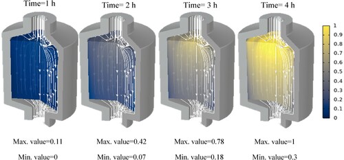
Figure A2. Phase distribution of TES tank using paraffin RT28HC.
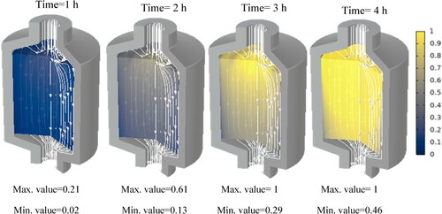
Figure A3. Phase distribution of TES tank using paraffin WAX..
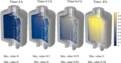
Figure A4. Phase distribution of TES tank using paraffin RT58.
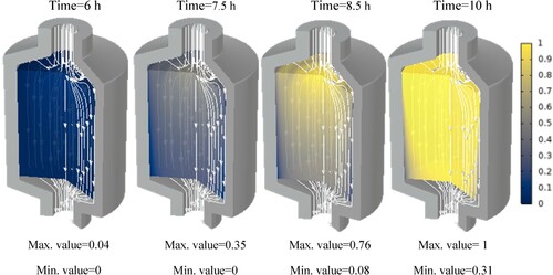
Figure A5. Phase distribution of TES tank using paraffin P56-58.