
 ?Mathematical formulae have been encoded as MathML and are displayed in this HTML version using MathJax in order to improve their display. Uncheck the box to turn MathJax off. This feature requires Javascript. Click on a formula to zoom.
ABSTRACT
Autonomous forestry machinery is necessary both to ensure safety and improve productivity. Previous research related to automation technology for forestry machinery has mainly focused on autonomous driving; research on log loading/unloading is still in progress. To automate the loading and unloading of logs, it is necessary to evaluate the errors of several processes quantitatively: detecting logs in the environment, estimating the gripping position, and controlling the machine. This paper focuses on the development of an autonomous log loading operation. This study aims to propose an estimation method for log gripping position based on log detection using instance segmentation. Evaluation of the proposed system shows that the root mean square errors in the radial, axial, and vertical directions are 0.162, 1.526, and 0.140 m for sparse logs, 0.384, 0.271, and 0.119 m for dense logs, and 0.764, 1.022, and 0.194 m for unorganized logs, respectively. Our results demonstrate that the proposed method is sufficiently accurate to achieve gripping of a single log; however, the accuracy is insufficient for gripping one in a dense group of logs accurately.
Introduction
Demand for autonomous forestry machinery has emerged as a response to both ensure safety and improve productivity on industrial scales. From a safety perspective, keeping people out of a forest, where heavy trees are handled in an unstructured and unstable environment ensures essential safety, can be achieved through the automation of forest machinery. From the productivity perspective, it has been noted that operators may become a bottleneck in productivity (Hellström et al. Citation2009). Replacing manual operations with automated machinery can lead to faster completion of work. Thus, automation of forestry machinery should be promoted.
In a cut-to-length (CTL) system, machines that can benefit from automation include harvesters and forwarders. Harvesters perform felling, delimbing, and driving; forwarders perform forwarding; i.e. log loading, driving, and unloading. These types of machine operations within a CTL system are inherently complex, regardless of the machine type or operation. To improve productivity and safety by introducing autonomous machinery into a CTL system, it is necessary to automate all operations of each specific machine. Felling requires gripping trees, cutting standing trees, moving logs, and driving, which requires handling long, heavy trees – which can exceed 20 m in length – in a forest environment that includes densely packed trees, uneven terrain, and restricted spaces. On the other hand, forwarding requires only gripping logs, driving, and unloading logs, typically ranging from 2 m to 6 m in length. Thus, the forwarder is relatively less complex than the harvester, and thus, has the potential for automation. Additionally, both forwarding and felling include gripping and handling logs, and log loading can also be applied to felling operations and log transportation by log trucks and trailers. This study has thus focused on the autonomous log loading operation.
Following the early success of autonomous driving of forestry machinery (Hellström et al. Citation2006; Ringdahl et al. Citation2011), several examples of autonomous driving or navigation have been reported in unmanned aerial vehicle flights of small robots (Smolyanskiy et al. Citation2017), vegetation removal (Mowshowitz et al. Citation2018), and wildfire prevention (Couceiro et al. Citation2019). However, research on autonomous driving and loading operations for forestry machinery has been limited compared to other automated systems, such as machinery used for construction or agriculture. Further, Visser and Obi (Citation2021) also noted that automation of forestry equipment lags larger industries such as agriculture, mining, or the military and one limitation for more extensive use of autonomous equipment is the lack of larger-scale market demand for harvesting machinery for the forest industry.
Compared with driving, few previous reports have addressed automated log loading; however, some recent research has reported progress in autonomous log loading the detection of logs in images (Usui et al. Citation2019; Usui Citation2021; Fortin et al. Citation2022; da Silva et al. Citation2022), the automation of the forwarder (Geiger et al. Citation2020, Citation2021, Citation2021), and the development of new machinery for unmanned operations (Lulea university of technology Citation2021) by integrating technologies for automated driving and log loading. Such research has the possibility for significant industrial breakthroughs. To apply these automated forwarders in practical forestry operations, however, certain technical issues need to be addressed.
In a CTL system, forwarders usually collect multiple logs near a spur road. During transportation by trucks, logs are loaded from log stacks onto the cargo bed of the truck. In this process, machinery is required to detect individual logs and choose the most appropriate log for loading. In addition, machinery often grabs multiple logs at the same time to reduce the operating time. To grab logs effectively with a swing-mounted grapple, determining the most appropriate position and orientation for gripping is critical. Our study, therefore, concentrates on estimating the gripping positions and orientations of the logs.
Automated object gripping/handling has been widely used in other industries (Tai et al. Citation2016), e.g. manufacturing (Fantoni et al. Citation2014), warehouse automation (Azadeh et al. Citation2019), and agriculture (Zhou et al. Citation2022). Specifically, the loading/harvesting operations of agriculture share many similarities with forestry operations because both handle natural objects in an uncontrolled environment. Kootstra et al. (Citation2021) referred that variation, incomplete information, and safety are the main challenges for selective harvesting robotics in agriculture. These challenges are also common in forestry. Many harvesting robots have been proposed for agriculture (Zhou et al. Citation2022), and their general operations have been reported (Jia et al. Citation2020) as follows: the harvesting robot approaches the plant through the walking device, the robot’s vision system identifies and locates the target fruit, the robotic arm guides the end effector to avoid the obstacle and approaches the harvesting target, the end effector harvests the target fruit, and the robot arm and the end effector store the harvested fruit. The methods of estimating the harvesting and gripping positions are usually similar in different harvesting robots, and many robots adopt the two-step process of (1) object detection and (2) gripping position estimation. This approach is also considered to be effective for automating log loading in forestry; in fact, similar approaches have been reported in several forestry studies (Usui et al. Citation2019; Geiger et al. Citation2020, Citation2021, Citation2021; Usui Citation2021; Fortin et al. Citation2022; da Silva et al. Citation2022). In particular, Geiger et al. (Citation2021) reported autonomous log loading with a control error of less than 5 cm using instance segmentation. However, few studies have investigated the accuracy of each process in autonomous log loading; e.g. environmental recognition, path planning for the grapple head, and control of the machinery. Thus, it is crucial to clarify the errors in each process to ensure more precise control, such as unloading from a forwarder or log stacking.
Focusing on each process of autonomous loading, investigators have proposed the detection of individual logs and trees from images using object detection (Usui et al. Citation2019; da Silva et al. Citation2022) and instance segmentation (Usui Citation2021; Fortin et al. Citation2022). Although these methods are capable of detecting individual logs, they use only the coordinates of the image coordinate system and not 3D coordinates. For example, da Silva et al. (Citation2022) proposed a standing tree mapping system based on object detection using an OAK-D camera; however, the positional accuracy of this system has not been reported.
A similar method using instance segmentation has been proposed by Grondin et al (Citation2022, Citation2023). Grondin et al. (Citation2022) reported systems for detecting standing trees from a situation obtained using a simulation. In addition, they proposed a dataset with keypoints and estimations based on deep learning, wherein trained models could estimate the cut position for felling a tree with an average error less than 7 cm. Their dataset was focused on harvesting operations. However, applying this keypoint-based method to log loading requires the labor-intensive annotation of a dataset of bucked logs with keypoints.
Geiger et al. (Citation2020) showed that it is possible to estimate the length and diameter of a log with errors of 7% and 18%, respectively, using a 3D point cloud created from segmented stereo images. However, no report of the precision of the global coordinates of this system has been provided. Similar methods for estimating log shapes using 3D sensors have been widely used for forest resource estimations. The estimation of log shapes using 3D sensors has included such approaches as laser scanning with TLS, hand-held LiDAR, and SfM-based image data acquisition (Bauwens et al. Citation2016; Wallace et al. Citation2016; Iglhaut et al. Citation2019; Hunčaga et al. Citation2020; Hyyppä et al. Citation2020). These methods, which rely on high-precision points, accurately estimate tree shape parameters represented by the diameter at breast height; however, they acquire large point clouds and extract the features of the trees from the data obtained. Collecting a sufficient number of points can therefore require multiple perspectives for each individual tree. Additionally, this large number of points used necessitates greater processing times.
Autonomous log loading requires real-time processing for the detection of individual trees because the environment, including the positions and numbers of logs, changes dynamically during the log loading process. Hence, it is difficult to obtain large point clouds from multiple or back-side viewpoints of the logs because the sensors installed on the loading machinery can only acquire single-view data. Consequently, a method is required for estimating the gripping positions of multiple logs in real-time using data from a single viewpoint.
The appropriate gripping position of the log is also important. This position can be selected from several candidates: the center of gravity of the log, the lengthwise center of the log, or the end of the log. Operators of forestry machinery typically grip logs horizontally using a swinging grapple, which is commonly equipped on forwarders. To achieve a horizontal grip, the center of gravity of the log must be selected as the gripping position. In addition, the path of the grapple head with the gripped log must be planned appropriately. If the log is gripped at an inclination – rather than in a horizontal orientation – the path must raise the grapple head and log to avoid the forwarder stakes. If the logs cannot be gripped horizontally during loading and unloading, the planned path can increase the operating time. Consequently, gripping the logs horizontally at their center of gravity improves the efficiency of loading and unloading by reducing the machine operating time. In this study, we have therefore adopted the center of gravity of each log as the gripping position. Herein, we propose a method by which the gripping positions and orientations of logs can be estimated.
Materials and methods
System overview
Determining the gripping position of a log first requires detecting it within the environment. Generally, this process uses “object detection” methods that detect a target with a rectangular shape. Recently, most object detections have been based on deep-learning methods. Various object detection methods, such as R-CNN (Girshick et al. Citation2014), Fast R-CNN (Girshick Citation2015), Faster R-CNN (Ren et al. Citation2017), and YOLO (Redmon et al. Citation2016), have been proposed. Specifically, YOLO has been reported to achieve a balance between accuracy and real-time operation. It is relatively easy to use in creating a training dataset because the supervised labels are rectangular.
Conversely, object detection methods must take into account both the target log and additional features, such as the ground or vegetation. Usui (Citation2023) proposed a method for estimating the gripping position of a log using rectangle detection but reported that the root mean square error (RMSE) remained at approximately 0.6 m due to the detection of objects other than logs. For these reasons, it is appropriate to use instance segmentation, which enables a more precise detection of individual logs in pixels, to estimate log-gripping positions accurately.
In addition, for this research, it is necessary to detect logs, estimate their gripping positions, and update the estimated gripping position as the chassis moves in real-time during autonomous log loading. For this purpose, we focused on YOLACT (Bolya et al. Citation2019) and YOLACT++ (Bolya et al. Citation2022), which are instance segmentation methods that perform real-time segmentation while maintaining accuracy. General instance segmentation such as Mask R-CNN (He et al. Citation2020) use feature localization, that employs a two-step detection process using a two-stage detector. Two-stage detectors process sequentially the information from a bounding-box region and employ mask prediction based on feature localization, which is difficult to speed up through parallelization. Rather than using feature localization, YOLACT generates a prototype mask and predicts a set of linear-combination coefficients at each instance, which can be accelerated by parallel processing. YOLACT++, an improved model based on YOLACT, incorporates deformable convolution into the backbone network, optimizing the prediction head by improving the anchor scale and aspect ratio. It also introduces a novel, fast, mask-rescoring branch. These features are refined to improve the model accuracy. As YOLACT++ can achieve mAP of 34.1 on MS COCO at 33.5 fps, it is both fast and accurate, and adopted it as the instance segmentation method for the logs in the present study.
The 3D coordinates of the grapple position were estimated using the following process. First, an image of the environment around the machinery was acquired using a camera. Next, each log was detected in the pixels from the obtained images by using instance segmentation. Then, the 3D points corresponding to the logs were extracted from the segmentation results, and the 3D points of the whole image were acquired from the stereo camera. Finally, the gripping position for each log was obtained by estimating the center of gravity of the detected points corresponding to that log. An outline of the processing algorithm is shown in . If an appropriate gripping position could not be determined in the above process, the estimated gripping position was not output. In this study, to evaluate the accuracy of the estimated gripping position for autonomous loading, the operation was assumed to consist of gripping a single log for loading, and the gripping positions for each detected log were estimated one by one. Each process is described in detail in the following sections.
Figure 1. The outline of the algorithm for estimating the gripping position and orientation of a log.
Datasets for instance segmentation
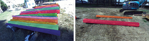
Images including logs and supervised labels are required for learning instance segmentation. Images for segmentation were acquired between September 2018 and September 2020 in Gunma Prefecture and between September 2020 and January 2022 in Ibaraki Prefecture. Both areas are located in the central part of Japan. The images from Gunma Prefecture included logs of the species Japanese cedar (Cryptomeria japonica), Hinoki cypress (Chamaecyparis obtusa Sieb. et Zucc.), and fir (Abies firma), while the images from Ibaraki Prefecture included only Japanese cedar. Stereo cameras (ZED and ZED2i, Stereolabs) were used to collect images of bucked logs at a resolution of either 1280 × 720 (ZED) or 2209 × 1242 pixels (ZED2i). The labels were created in MS COCO format, with 7466 log annotations for a total of 3262 images. Some examples of labeled images are shown in . The annotation class is “log” only; tree species were not classified. All annotations were labeled manually. Only logs for which the whole part is shown within the image were annotated.
Figure 2. Examples of labeled images.
Empirically, when creating a machine learning model, the model is optimized by using 80% of the dataset as training data (Gholamy et al. Citation2018). Therefore, for evaluation the dataset obtained for the logs was divided into training/validation and test datasets at a 90/10 ratio. Subsequently, the rest of the training/validation datasets were randomly divided into training and validation datasets in an 80/20 ratio. Thus, three datasets for training, validation, and testing, with 2348, 588, and 326 images, respectively, were obtained.
Tracking logs using multiple object tracking
It is not possible to determine whether the same log is being detected continuously, even in temporally continuous images, because of the instance segmentation model processes involved in each image.
It is desirable to detect logs to be grappled continuously during camera and machine movement in order to update the position coordinates of the logs to be grappled. In addition, momentary misdetections of the log were assumed. In this case, temporally discontinuous detections may be excluded from gripping position candidates by temporarily continuous object tracking. Multiple object tracking (MOT) was adopted to estimate the gripping position. For the MOT scheme, this study uses simple online and real-time tracking (SORT, Bewley et al. Citation2016), which does not use any appearance information about the tracked object. Instead, SORT handles motion prediction and data association using a Kalman filter (Kalman Citation1960) and the Hungarian algorithm (Kuhn Citation1955) based on a bounding box of external object detections. These simple algorithms can handle fast tracking. The tracking accuracy of SORT depends on the accuracy of the detected bounding box. Thus, high accuracy detection makes SORT both fast and accurate. In this study, log tracking was performed by using SORT to process bounding boxes that encompass the mask of each log after segmentation. Logs detected in both the previous and the current frames were selected as candidates, and their gripping positions were then estimated. Other detected logs were considered misdetections, and their results were discarded.
Acquisition of 3D points and estimation of the gripping position and orientation
First, a mask image was created from the pixels that included the logs detected by instance segmentation and tracking. Second, the mask image was integrated with 3D points created from the stereo images using a stereo camera software development kit (Stereolabs Citation2023). As a result, 3D points were obtained that corresponded to the detected logs. It was predicted that estimating the center of gravity of the log would bias the estimate toward the visible part of the log. To overcome this potential bias, the gripping position was selected to be the log-surface point (gs) nearest to the log’s center of gravity (g), since log-surface points are easy to measure directly. This point gs obtained from the 3D points of the detected logs was estimated to be a candidate for the gripping position of the log. shows an outline of this gripping position. This process for a single log was repeated until all the logs in the image had been processed. After searching for the point closest to the center of gravity for all of the logs detected in the image, the candidate closest to the camera was used as the estimated gripping position. 3D points were created only from stereo images obtained at the same time as the instance segmentation. Consequently, 3D points within the range visible from the stereo images were used for processing. The estimation of the log’s orientation was carried out simultaneously with the estimation of the gripping position. Principal component analysis was performed on the detected 3D points of the log. The eigenvector corresponding to the largest eigenvalue was selected as the gripping orientation of the log. Each estimation process used only single 3D points from stereo images. The proposed method for estimation of the log gripping position does not output gripping positions for the simultaneous gripping of multiple logs, since the primary objective in this paper is to evaluate the gripping position for a single log.
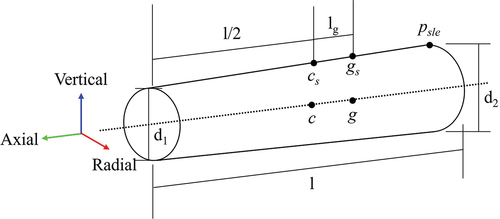
Figure 3. The outline of the estimated gripping position and evaluation axis in the log coordinate system.
During the processes described above, it is important to prevent the outputting of coordinates with huge errors due to misdetections of the logs. Therefore, candidates for the gripping point were filtered to lie within the range 2.7 to 6.0 m, which lies within the working range of the grapple loader (SK50SR, Kobelco) used in this study.
To evaluate the accuracy of the proposed system for estimating the gripping position, we implemented it on a robot operating system (ROS); i.e. a software platform for robots. The data obtained from the stereo camera were saved in a log file and processed separately after the experiments on a computer (CPU Intel Core i9-10900K @ 3.70 GHz, memory 128 GB, GPU NVIDIA GeForce RTX 3090, OS Ubuntu 20.04).
Field experiments
To evaluate the proposed system, three types of field experiments resembling realistic operations were conducted at Ibaraki Prefecture: (1) an experiment on 14 July 2022 in which the logs were arranged separately; (2) an experiment on 11 July 2022 in which the logs were arranged densely and close to each other, assuming stacking; and (3) an experiment on 20 July 2023 in which the logs were arranged disorderly.
It is important to note that during these experiments, only data acquisition was carried out, and real-time estimations of log gripping positions were not performed. Consequently, to evaluate the real-time capability of the gripping position estimations necessary for automated log loading, the processing time required for each gripping position estimation was also recorded.
For the assessment of instance segmentation during the experiments, 10 images from each experiment were labeled, resulting in a total of 30 images evaluated for feasibility. In an assumed automated operation, the logs move out of the camera’s field of view after being gripped Therefore, the gripping positions closest to the camera are presented sequentially. However, in the experiments conducted for this study, the logs were not moved. Thus, the log closest to the camera was identified as the gripping position while the grapple chassis was in motion.
Experiment 1: sparse logs
This first experiment assumed a situation in which the logs were placed separately. This corresponds to a case in which logs are left spaced relatively far apart in the forest, assuming forwarding in a CTL system. Five Cryptomeria japonica logs, each 4 m in length, were placed on a flat surface, spaced apart. The large ends of the logs were arranged in front of the grapple loader at the beginning of the experiment. A grapple loader equipped with a stereo camera (ZED2i, Stereolabs) was moved around the logs, and images of the logs were collected continuously. The camera was installed pointing at a downward angle of 0.504 radians.
By rotating the upper swing body of the grapple loader 90 degrees against the direction of movement, the captured images always included the logs. During 170 s of video recording, 2289 images were captured. shows the experimental setup, and shows the trajectory of the chassis and the positions of the logs during the experiment. The shapes of the logs used in this experiment are presented in .
Figure 4. Experimental setup.
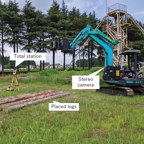
Figure 5. Trajectory of the machine chassis in the experiment by using simultaneous localization and mapping (SLAM).
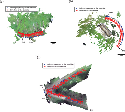
Table 1. Log-shape statistics.
Experiment 2: dense logs
Next, an experiment was performed for a situation in which logs were positioned densely next to each other. This situation corresponds to operations such as unloading from the forwarder bed and loading from a log stack in a CTL system. Ten Cryptomeria japonica logs, each 4 m in length, were placed next to each other on a flat surface. Images were collected by driving around the logs using the same method as described above for the sparse logs experiment, except that the camera was installed on the grapple loader pointing at downward angle of 0.241 radians. Here, 524 images were obtained over 59 seconds. shows the trajectory of the chassis and the position of the logs during the experiment.
Experiment 3: unorganized logs
Finally, an experiment was performed for a situation with randomly placed, unorganized logs surrounded by trees to simulate the real environment in the forest. Sixteen Cryptomeria japonica logs, each 4 m in length, were placed in the forest. The experimental equipment and method were the same as described above for the sparse and dense logs experiments, with the camera installed pointing downward at an angle of 0.346 radians. Here, 2259 images were obtained over 600 seconds. shows the trajectory of the chassis and the position of the logs during the experiment. In this third experiment only, it was anticipated that the positions derived from the self-localization of the camera could result in errors in the estimations of the gripping positions due to the considerable driving distance covered during the experiment. Therefore, the position of the grapple chassis was measured using a total station (TS, IS303, TOPCON).
Evaluation
Evaluation of instance segmentation
Generally, precision and recall are used to evaluate machine learning. To evaluate the log detection accuracy, recall, average precision (AP; Everingham et al. Citation2010), and mean AP (mAP) in COCO evaluation metrics, commonly used indices for evaluating instance segmentation, were used. Because mAP requires a threshold for determining a successful detection, the intersection of union (IoU), which indicates the overlap ratio between the estimation and true area, is used as the index threshold.The indices recall50, AP50, and mAP were used; recall50 and AP50 denote the values of recall and mAP for a threshold of IoU = 0.50, and mAP considers values of IoU in the range 0.50–0.95.
Evaluation of gripping positions and orientations
The process for evaluating gripping positions and orientations is explained below. First, the direction of the axis on the surface of each log was measured in advance, using a TS to measure the large end and the center of each log, and the coordinates of the estimated gripping position were converted into the coordinate system of the TS. To evaluate the errors from the aspect of the important direction, the errors in the gripping position were evaluated by using coordinate transformations in the radial, axial, and vertical directions of the log coordinate system. Each evaluation axis is shown in . Similar to the evaluation of the gripping position, the coordinates of rotational errors were transformed into the radial, axial, and vertical directions in the log coordinate system. In this study, the rotations around the radial, axial, and vertical axes of the log were referred to as roll, pitch, and yaw, respectively.
The true value of the gripping position of each log in the TS coordinate system was calculated from the measured center of the log’s length on its surface and the calculated center of gravity on the log. For each log, the point cs at the center of the log’s length (c) on its surface and the point psle at the large end of the log on its surface were measured using the TS. The length between the small end of the log and its center of gravity, l/2 + lg, was calculated from the length l of the log and the diameters (d1 and d2) of the small and large ends of the log, assuming the log to be a truncated cone. Here, lg is the length from the center of the log to its center of gravity in the axial direction along the log. The axial vector on the surface of the log was calculated from the difference between cs and psle.
Based on the measurements and calculations described above, the true value of the gripping position was calculated from the difference along the log’s axial vector between cs and the product of lg and the log’s axial direction in the axial vector between cs and lg on the surface of the log. The true value of the orientation was set to be the axial vector on the surface of the log in the TS coordinate system. In calculating the axial vector on the log’s surface as mentioned above, a discrepancy arises between the axial vector on the log’s surface and the internal axial vector (from c to g) in the log’s vertical direction, attributable to the log’s taper along its axis. However, this bias was not removed. One of the 3D coordinates of the center of gravity on the log in the sparse logs experiment was obtained from the stereo camera images and was used as the target gripping position because the coordinates could not be obtained from the TS. The errors were calculated from the difference between the true value of the gripping position closest to the estimated gripping position and the estimated gripping position. The errors were evaluated as RMSEs.
Evaluation of the graspable range
The most critical factor when gripping a log is ensuring that the gripping position falls within the graspable range of the grapple head. If there is an error in the estimated gripping position along the log’s axial direction, it is still feasible to grip other parts of the log. In the case of a swinging grapple, the log can become tilted, depending on the gripping position. Consequently, it is conceivable that the grapple head could be negatively influenced during automated control by swinging due to gripping out of the center of gravity. In contrast, a fixed grapple could be less influenced by such tilting, as it can maintain its hold on the log regardless. Therefore, it is considered that errors in the axial direction are acceptable for a fixed grapple; however, log gripping could fail if an error in the radial direction or the vertical direction were to leave the log outside of the graspable range of the grapple head. Similarly, orientation of the grapple head needs to be generally aligned with the roll and yaw of the log in the aspect of log gripping availability. Conversely, the pitch orientation does not affect the gripping process. Therefore, this study evaluated the roll and yaw directions of the log. The errors in the roll and yaw orientations were considered to be acceptable if they fell within the maximum graspable range of the grapple head. The conditions necessary for gripping logs are therefore as follows:
The grapple coordinate system is established as shown in . The estimated gripping position is assumed to be aligned with the center of the graspable range of the grapple head. Moreover, the gripping orientation is also assumed to be aligned with the Z-axis of the grapple coordinate system and the direction of the estimated gripping orientation. When the gripping position is accurately determined, it is presumed that gripping can be achieved. Since the gripping position was evaluated in the log coordinate system, the graspable range was evaluated using the transformed points of the estimated gripping position in the grapple coordinate system, as described below:
Figure 6. A three-dimensional diagram of the grapple head.
Let P be defined as a set of points that have the positions x, y, z, and orientations θ, φ, ψ (EquationEquation 1(1)
(1) ):
Here, θ, φ, and ψ represent the roll, pitch, and yaw of a given log, respectively. From the aspect of the gripping position, the gripping range is confined within a circle defined by the trajectory of the grapple arm’s tip, originating from the rotation center of the grapple arms. Consequently, considering both grapple arms, the following conditions are set (EquationEquations 2(2)
(2) and Equation3
(3)
(3) ). Assuming c1 (a1, b1) and c2 (a2, b2) are the xy coordinates of the rotation centers of the grapple arms (a1 < a2):
Here, R represents the length of the grapple arms. As the rotation center of the grapple arms is located above the upper limit of the graspable range of the grapple head, b1 and b2 can be written as follows (EquationEquation 4(4)
(4) ):
Here, H is the maximum gripping height, where the left and right arms overlap at the center of the grapple head, Hc is the distance from the upper limit of the graspable range of the grapple head to the rotation center of the grapple arms, and xc and yc are the coordinates of the center of the graspable area. Furthermore, considering that the gripping range is situated below the rotation center of the grapple arms and the range is from the maximum length L of a grapple arm, the following conditions are imposed (EquationEquations 5(5)
(5) and Equation6
(6)
(6) ):
If the point p1 lies on the circle with center c1 that has the smallest value of x satisfying condition C, and the point p2 lies on the circle with center c2 that has the largest value of x satisfying condition C, then their coordinates are p1 (xc−l/2, yc−H/2) and p2 (xc+l/2, yc−H/2). Additionally, if the points p3 and p4 have the smallest values of y satisfying conditions A and B, respectively, they can be represented as p3 (a1, b1−R) and p4 (a2, b2−R). Since p1 and p2 correspond to the coordinates of the tips of the grapple arms at the maximum open position, the graspable range is defined as a polygon with the coordinates c1, c2, p1, p2, and the trajectory of the grapple arms tips. That is, if we define p5 (xc−L/2, b1−R) and p6 (xc+L/2, b2−R), then (EquationEquation 7(7)
(7) ):
Here, Pvertex is defined as follows (EquationEquation 8(8)
(8) ):
From the aspect of gripping orientation, it is imperative that the rotated log remain within the graspable area. This establishes the following (EquationEquations 9(9)
(9) and Equation10
(10)
(10) ):
Here, W is the width between the grapple arms. Overall, the conditions that define graspable area are as follows (EquationEquation 11(11)
(11) ):
Here, Pin defines the set of points that are within the graspable area of the grapple head.
The specifications of the grapple head used in this study (BHS10MMR–3, Nansei Machinery) are as follows: R is 0.660 m, L is 1.430 m, H is 0.458 m, Hc is 0.035 m, and W is 0.402 m, respectively.
Alignment of the coordinate systems
The estimated gripping positions and orientations were output in the ROS coordinate system. To compare these positions with the true, measured values of the gripping positions of the logs in the TS coordinate system, it is necessary to align the ROS coordinate system with the TS coordinate system. The alignment procedure is detailed below. For the experiments with both sparse and dense logs, the initial camera position and orientation in the ROS coordinate system were aligned with the TS coordinate system at the start of the measurements. This process established a transformation between the initial positions of the TS and ROS coordinate systems. The gripping positions estimated during camera movements were subsequently transformed into the TS coordinate system. During this process, the positions and orientations of the camera in the ROS coordinate system were calculated using simultaneous localization and mapping (SLAM), which outputs the map and position/orientations of the camera. Finally, all the estimated gripping positions were transformed into the TS coordinate system by applying coordinate transformations using the initial position of the camera and the positions and orientations of the camera during each experiment.
For the unorganized logs, it was anticipated that significant positional and orientational errors could arise using the aforementioned approach due to the extended measurement times and travel distances. Therefore, a transformation between the TS and ROS coordinate systems was performed via a point cloud map. The coordinates were transformed by aligning the large end of each log in both coordinate systems. The positions of the large end of each log in the ROS coordinate system were obtained manually from the points acquired from SLAM. The positions and orientations of the camera in the ROS coordinate system at each time were estimated using the same approach as for the sparse and dense logs.
Results
Results using instance segmentation
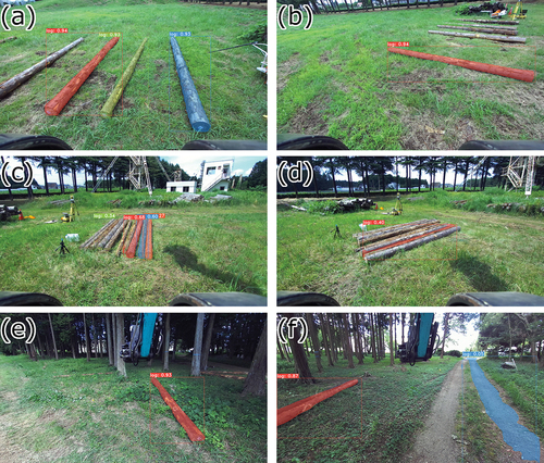
The results of training in log detection using instance segmentation are shown below. Here, recall50 was 46.61, mAP was 62.01, and AP50 was 74.37 in the test dataset. The segmentation accuracy in each of the three experiments were recall50 of 33.12, 14.59, and 22.73; mAP of 45.59, 10.75, and 24.93; and AP50 of 59.41, 22.90, and 40.59 for the sparse logs, dense logs, and unorganized logs, respectively. Examples of detections and misdetections in the test dataset and the experiments are shown in and .
Figure 7. Examples of log detection in the test dataset.
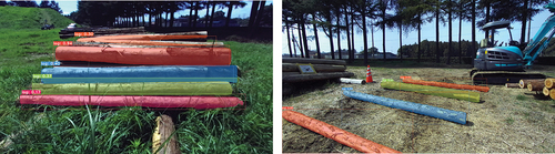
Figure 8. Examples of log detection during the experiments.
Estimation of the gripping positions of the logs
shows the errors in the estimated gripping positions. For the sparse logs, the RMSE was 0.162, 1.526, and 0.140 m in the radial, axial, and vertical directions, respectively. For the dense logs, the RMSE was 0.384, 0.271, and 0.119 m in the radial, axial, and vertical directions, respectively. For the unorganized logs, the RMSE was 0.764, 1.022, and 0.194 m in the radial, axial, and vertical directions, respectively. shows the errors in estimated gripping orientations. For the sparse logs, the RMSEs of the orientation errors were 0.249, 0.388, and 0.533 radians in roll, pitch, and yaw, respectively. For the dense logs, the RMSEs were 0.231, 0.594, and 0.617 radians in roll, pitch, and yaw, respectively. For the unorganized logs, the RMSEs were 0.274, 0.736, and 0.288 radians in roll, pitch, and yaw, respectively. The estimated positions and orientations in each experiment are illustrated in . Additionally, to illustrate the estimated gripping position and orientation in 3D, the viewpoint was rotated by π/4 radians around both the X-axis and Y-axis in the TS coordinate system. These rotated viewpoints are shown in and . Note that not all estimated orientations of the logs are displayed in in order to enhance the visibility of the figures. The processing times for the entire set of experiments were as follows: instance segmentation and MOT took an average of 147 milliseconds, while the estimation of the gripping position and orientation, as described in the section “Acquisition of 3D points and estimation of the gripping position and orientation,” took an average of 35 milliseconds. In total, an average of 183 milliseconds was required from image acquisition to the output of the gripping position.
Figure 9. Estimated positions of gripping logs.
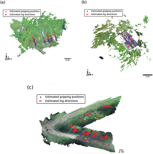
Figure 10. Estimated positions of gripping logs rotated through π/4 radians around the X-axis.
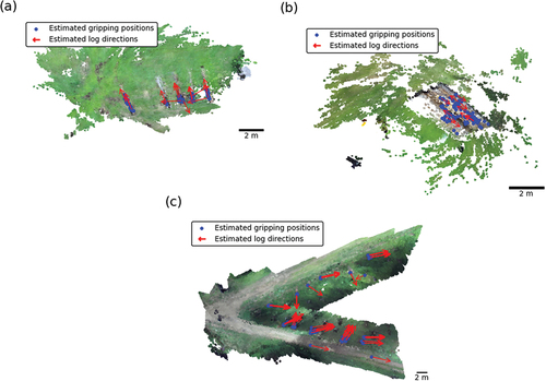
Figure 11. Estimated positions of gripping logs rotated through π/4 radians around the Y-axis.
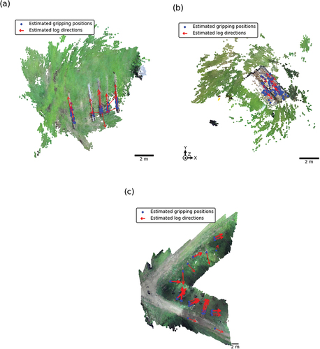
Table 2. Gripping position estimation results.
Table 3. Gripping orientation estimation results.
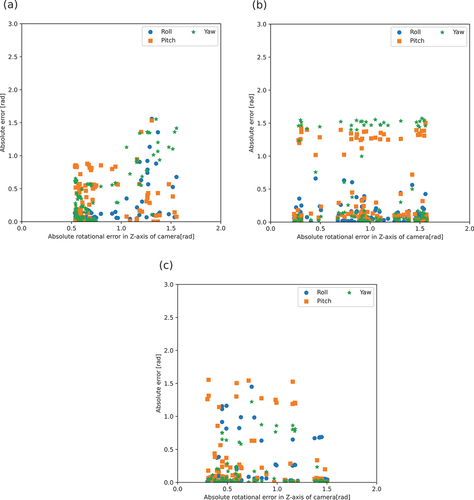
The method proposed in this study for estimating the gripping position utilizes single-shot information from the camera’s field of view, potentially introducing errors due to occlusion. To analyze this, the rotational errors in the camera coordinate system were calculated as shown in . The effect of log occlusion was evaluated by calculating the rotational error between the log’s orientation and the camera’s X-axis. In this study, the rotational errors around the Z-axis of the camera corresponding to the log’s yaw, were considered to be crucial indicators of the log’s orientation relative to the camera The alignment between the yaw angle of the log and the Z-axis of the camera is not entirely congruent due to the installation of the camera. shows the absolute rotational error between the camera and the axis of the log, along with the positional errors of the log-gripping position in each axis. illustrates the absolute rotational error between the camera and the axis of the log, along with the rotational errors of the log-gripping position in each axis.
Figure 12. Evaluation outline of the log-camera rotational errors in the camera coordinate system.
Figure 13. The positional relations of the absolute rotational error between the X-axis of the camera and the log orientation around the Z-axis of the camera.
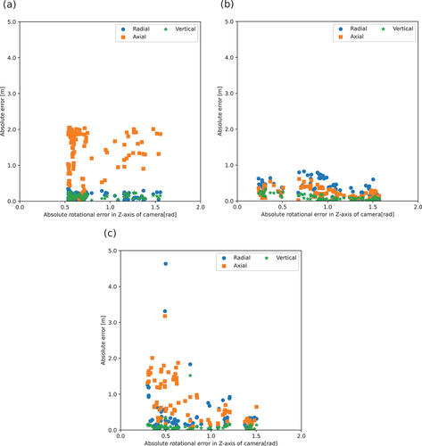
Figure 14. The orientational relations of absolute rotational error between the X-axis of the camera and the log orientation around the Z-axis of the camera.
Discussion
Log detection using instance segmentation
Detecting the shapes of logs is important for assuring the accuracy of the proposed estimation method. Logs were detected with AP50 of 74.37 and mAP of 62.01 on the test set. Usui (Citation2021) reported that logs were detected with mAP 81.1 by combining training using 295 images and RandAugment (Cubuk et al. Citation2020) using Mask R-CNN (He et al. Citation2020). Fortin et al. (Citation2022) also reported that Mask2Former (Cheng et al. Citation2022) detected logs with mAP of 57.53 using the TimberSeg 1.0 dataset, which consists of 220 images containing 2500 instances of logs. In addition, Fortin et al. (Citation2022) reported that both precision and recall achieved an accuracy of 80% when considering the 0.5 IoU curve. The result of instance segmentation in the test dataset of this study was 74.4 in AP50 and 62.01 in mAP using YOLACT++; it is slightly lower but of almost the same accuracy as in previous research.
Compared to the test dataset, during the experiments the mAP and AP50 exhibited lower values across all experiments. As demonstrated in , certain logs remain undetected in each test. Consequently, when applying these segmentation methods into autonomous loading, there is a risk of overlooking and failing to load all of the logs. Therefore, improving the log segmentation accuracy for the practical application of the proposed method is necessary.
To address this issue, two possible solutions were suggested: (1) the use of high-precision segmentation and (2) the implementation of data augmentation. Regarding high-precision segmentation, various methods, including Mask-R-CNN (He et al. Citation2020) or Mask Scoring R-CNN (Huang et al. Citation2019), have shown higher accuracy compared to the YOLACT++ employed in this study. While these methods exhibited slower performance than YOLACT++, it is anticipated that they could enhance the segmentation accuracy of the logs. Concerning data augmentation, research suggests that techniques such as simple copy and paste methods (Ghiasi et al. Citation2020) can enhance accuracy. Thus, future application of such methods could lead to improved detection of missed logs.
Trends of the estimated results
For the sparse and unorganized logs, errors in the axial direction tended to be higher than along either the radial or vertical axes, reaching a maximum of 2.052 m for the sparse logs and 3.175 m for the unorganized logs. Conversely, the dense logs exhibited lower axial RMSEs. These error trends appear to be due to the log shapes and to misdetections. In general, significant errors were observed when a non-log point was erroneously identified as a log. In the case of the unorganized logs, notable errors in the estimated gripping positions were observed, primarily due to the misdetection of the road as logs. An example of such misdetection is shown in . Furthermore, gripping positions estimated in this study were extracted from points on the surfaces of the detected logs. Consequently, the estimated gripping position did not deviate outside the log. Since the axial length of a log was longer than its extent in either the radial or the vertical direction, the range of estimated gripping positions in the axial direction was larger than that in either the radial or vertical directions.
In this study, all the detected logs were processed uniformly, regardless of their instance segmentation score, which indicates the reliability of the detection. Misdetections of the road during log segmentation resulted in low scores. In contrast, logs were detected with higher scores, over 0.9 in close range. This result thus indicates that the scoring threshold employed can contribute to the exclusion of misdetections of the logs. To validate the effect of the scoring threshold, it was applied using scoring thresholds ranging from 0.0 to 1.0 to the instance segmentation in the experiment with unorganized logs. Thus, it was observed that the evaluation metrics resulted in mAP 28.63 with scoring thresholds of 0.4–0.9 and AP50 of 44.55 with scoring thresholds of 0.2–0.3. Therefore, based on these scores, errors due to misdetections can be decreased by setting appropriate thresholds.
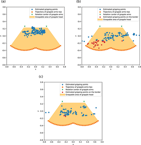
Based on EquationEquation (11)(11)
(11) , there were 74 (52.1%) points in the graspable range of the grapple head in the sparse logs experiment, 50 (46.3%) points in the dense logs experiment, and 53 (61.6%) points in the unorganized logs experiment. The points in the graspable range in each experiment are depicted in . Based on EquationEquation (2)
(2)
(2) and (Equation3
(3)
(3) ), the rotation centers of the grapple arms and the trajectories of the grapple arms tips are also shown in . In this study, the estimated gripping position was set on the log surface. Therefore, if the estimated gripping position was located near the lower limit of the Y-axis in the gripping range, it could result in a trajectory where the grapple merely contacts the surface of the log. Conversely, it is possible to achieve a successful grip with the grapple arms even when the gripping points are located above the upper part of the log, potentially causing the grapple arms to become embedded into the log’s surface. To distinguish between these situations, the estimated gripping points were separated into two categories: (1) with Pin in the center of the circular cross section on the log or (2) not. In the first condition, Pin is within the lower part of the log; this condition was called “graspable.” In contrast, the second condition meant that Pin was within only the upper part of the log; this condition was called “on the border.” Based on these categories, there were 74 (52.1%) “graspable” points in the sparse logs experiment, 39 (36.1%) points in the dense logs experiment, and 50 (58.1%) points in the unorganized logs experiment. Similarly, there were 11 (10.2%) “on the border” points in the sparse logs experiment, none in the dense logs experiment, and 3 (3.5%) points in the unorganized logs experiment. These results indicate that almost half of the points were within the graspable range across the experiments. Even when focusing solely on the points categorized as “graspable” in the graspable range, more than half of the points were within Pin for the sparse logs and unorganized logs. Consequently, more than half of the estimated points in sparse logs and unorganized logs could be gripped successfully, assuming that they were gripped one by one. However, in dense logs scenarios, such as loading or unloading from log stacks or from the platform of a forwarder, precise manipulation is required to insert the grapple arms into the spaces between logs. The estimation method proposed here exhibited an RMSE of 0.384 in the radial direction for dense logs; hence, it is not appropriate for gripping a single log from a dense pile of logs.
Figure 15. Points in the graspable range in each experiment.
Error factors
A plurality of factors can be considered as causes of error. The first error factor considered is in self-position estimation of the grapple chassis using SLAM. In our experiments, the gripping positions of logs were estimated during movements of the machine and camera in order to simulate a real operation. Therefore, an inaccurate position or orientation of the chassis results in an error in the global coordinate system even if the gripping positions are accurately estimated in the local coordinate system of the machine. The position and orientation of the machine were acquired from the stereo camera software development kit using SLAM, and the accuracy of the self-position estimation using images, i.e. the visual SLAM depends on the situation. Merzlyakov and MacEnski (Citation2021) also reported a benchmark in stereo visual SLAM, observing a 0.04%–0.11% localization error in the outdoor KITTI dataset. In addition, Sharafutdinov et al. (Citation2023) reported a benchmark accuracy for the major open-source visual SLAM, observing that the localization accuracy was 0.02–0.11% for the same KITTI dataset.
The distances traveled in the sparse logs, dense logs, and unorganized logs experiments were calculated from the position coordinates to be 35.154, 6.893, and 288.231 m, respectively. Assuming an error in the range from 0.02% to 0.11%, localization errors of 0.007–0.039 m in the sparse logs experiment, 0.001–0.008 m in the dense-logs experiment, and 0.058–0.317 m in the unorganized-logs experiment may have occurred. The RMSE of the grapple chassis trajectory between the measured using the TS and calculated using the positions and orientations obtained from SLAM was 0.237 m for the unorganized logs. This corresponds to an error of 0.082%, which is similar in accuracy to previous research (Merzlyakov and MacEnski Citation2021; Sharafutdinov et al. Citation2023). These errors may have exerted a limited influence on operations, since the coordinate values required for automated operations were those expressed in the local coordinate system of the machine.
A second error factor is log occlusion. In our experiments, the gripping position was estimated individually from the point cloud acquired from the stereo camera at each time. That is, neither the former nor the latter point cloud continuous in time were used in estimating the gripping position. Thus, the only information used was that obtained from the visible range to the camera, and blind-spot information could not be used. The density and accuracy of point clouds decrease with increasing distance; in these situations, a sufficient quality and quantity of point clouds cannot be obtained for analysis. It is possible that this factor significantly affects the estimation of the center of gravity from the point cloud. The positional errors in show that a smaller absolute rotational error between the camera and the log corresponded to an increased axial error in the dense logs and unorganized logs experiments (p < 0.001). The correlation coefficients between the absolute rotational error of the camera and the positional-orientational errors along each axis are depicted in . A state with minimal absolute rotational error between the camera and the log orientation represents an alignment of the axis of the log with the X-axis of the camera, indicating that the log is oriented vertically to the camera. In this configuration, a smaller number of log points was obtained far from the camera, whereas a larger number of log points was obtained near the camera. The variability in the number of points depending on the distance from the camera is one of the factors contributing to the axial errors in the estimated gripping positions.
Table 4. Correlation coefficients.
Lindroos et al. (Citation2015) considered the positional accuracy of harvester heads required for various forestry operations and argued that centimeter-level accuracy is essential for machine automation. To automate forestry operations, the lowest positional accuracy in each process is the bottleneck for the accuracy of the entire work. Therefore, the positional accuracy for gripping the target tree or log – as well as the positional accuracy of the harvester head – must be accurate at the centimeter scale.
In our experiments, the gripping positions were estimated with a radial RMSE of 0.162 m for the sparse logs, 0.384 m for the dense logs, and 0.764 m for the unorganized logs, respectively. These positions are of sub-meter accuracy, but they are not of cm – mm accuracy, which Lindroos et al. (Citation2015) have argued to be essential for machine automation. It is therefore concluded that using the system proposed in this research for estimating the gripping position, it is possible to grip logs only when they are separately placed. However, it is not possible to satisfy the accuracy required for loading/unloading from stacked logs or from the loading platform of a forwarder. For operations that require precise control, it can be possible to improve the accuracy in estimating the gripping position by using the following methods: (1) stopping the movement and averaging the measurements when estimating the gripping position; (2) reducing blind spots due to occlusion by simultaneously mapping with technologies such as visual SLAM and using blind-spot information; or (3) equipping the grapple chassis with another sensor such as LiDAR that is capable of measuring more precise information. Since the first solution is effective only for reducing the variance of the estimated gripping position, the rest of the solutions were considered effective for the biased errors in estimation; e.g. when a point cloud of only a part of a log is acquired due to occlusion.
The system proposed in this study processes each acquired image. To estimate the gripping position accurately, it is necessary that the entire log be detected within the camera frame because the segmentation dataset includes only entire logs, not parts of the logs. Nevertheless, there is a potential for utilizing information about the entire log even if a part of the log is outside the camera’s field of view, provided that supplementary data, images, or points concerning the camera’s blind spots are available, possibly through techniques such as like SLAM-based mapping.
The integrated system proposed in this study involves the stereo camera based system being used mainly to move the grapple head from a visible distance to the vicinity of the gripping position. The installation of a distance sensor such as LiDAR at the grapple head, could be used to correct the gripping position and plan the path of the tip of the head. Furthermore, the step to autonomous forest machinery has other problems; i.e. complex control of hydraulic systems. The hydraulic systems used in forest machinery exhibit non-linearities due to actuators, cylinders, and delays. The same problem occurs in the automation of construction machinery (Dadhich et al. Citation2016). It is therefore a strong challenge to control the grapple head precisely for autonomous log loading. Quantitative step-by-step analyses of the errors in each of these processes including this study could ultimately lead to precise autonomous control for forest machinery.
The methodology of this research could be extended to estimate the gripping positions and log orientations of multiple logs by processing closely segmented logs, while the estimation of gripping positions in this study was initially directed at individual logs. However, in actual loading operations the handling of multiple logs simultaneously is a common practice. Therefore, it is important for future studies to consider expanding the proposed methodology to encompass the estimation of gripping positions for handling multiple logs.
Conclusions
This study proposed a method for estimating the gripping positions of logs by integrating log detection with instance segmentation and evaluated its feasibility for use in a realistic log loading environment. The resulting estimations of the positions for gripping logs exhibited RMSEs in the radial, axial, and vertical directions of 0.162, 1.526, and 0.140 m for sparse logs; 0.384, 0.271, and 0.119 m for dense logs; and 0.764, 1.022, and 0.194 m for unorganized logs, respectively. From calculations based on the dimensions of the grapple head used in this study, 52.1% of the points were within the graspable range of the grapple head for the sparse logs, 36.1% for the dense logs, and 58.1% for the unorganized logs. The method presented herein is sufficiently accurate to enable the grapple arms to grip a single, sparse log; however, it did not have the accuracy required to grip dense logs. For operations that require precise control, such as loading log stacks, the accuracy of the proposed approach may be enhanced by combining the system presented in this research with visual SLAM-based mapping to reduce blind spots and using LiDAR for short-range sensing capabilities. This system for estimating the gripping positions could be employed in the development of autonomous forestry machinery.
Acknowledgements
Authors would like to thank the staff of Forestry Agency Forest Mechanization Center for technical assistance with the experiments and providing us with the field.
Authors acknowledge the use of ChatGPT for grammar check in the preparation of this research paper.
Disclosure statement
No potential conflict of interest was reported by the author(s).
Additional information
Funding
References
- Azadeh K, De Koster R, Roy D. 2019. Robotized and automated warehouse systems: review and recent developments. Transp Sci. 53(4):917–945. doi: 10.1287/trsc.2018.0873.
- Bauwens S, Bartholomeus H, Calders K, Lejeune P. 2016. Forest inventory with terrestrial lidar: a comparison of static and hand-held mobile laser scanning. Forests. 7(12):127. doi: 10.3390/f7060127.
- Bewley A, Ge Z, Ott L, Ramos F, Upcroft B. 2016. Simple online and realtime tracking. Proceeding of 2016 IEEE International Conference on Image Processing; Sep 25-28; Phoenix, AZ. p. 3464–3468.
- Bolya D, Zhou C, Xiao F, Lee YJ. 2019. YOLACT: real-time instance segmentation. Proceedings of the IEEE/CVF International Conference on Computer Vision; Oct 27- Nov 2; Seoul, Korea (South). p. 9157–9166.
- Bolya D, Zhou C, Xiao F, Lee YJ. 2022. YOLACT++: better real-time instance segmentation. IEEE Trans Pattern Anal Mach Intell. 44(2):1108–1121. doi: 10.1109/TPAMI.2020.3014297.
- Cheng B, Misra I, Schwing AG, Kirillov A, Girdhar R. 2022. Masked-attention mask transformer for universal image segmentation. Proceeding of IEEE/CVF Conference on Computer Vision and Pattern Recognition; Jun 18-24; New Orleans, LA. p. 1290–1299.
- Couceiro MS, Portugal D, Ferreira JF, Rocha RP. 2019. SEMFIRE: towards a new generation of forestry maintenance multi-robot systems. IEEE/SICE International Symposium System Integration SII. 2019; Jan 14-16; Paris, France: IEEE/SICE. p. 270–276.
- Cubuk ED, Zoph B, Shlens J, Le QV. 2020. RandAugment: practical automated data augmentation with a reduced search space. Proceeding of IEEE/CVF Conference on Computer Vision and Pattern Recognition Workshops; Jun 14-19; Seattle, WA. p. 3008–3017.
- Dadhich S, Bodin U, Andersson U. 2016. Key challenges in automation of earth-moving machines. Autom Constr. 68:212–222. doi: 10.1016/j.autcon.2016.05.009.
- da Silva DQ, dos Santos FN, Filipe V, Sousa AJ, Oliveira PM. 2022. Edge AI-based tree trunk detection for forestry monitoring robotics. Robotics. 11(6):136. doi: 10.3390/robotics11060136.
- Everingham M, Van Gool L, Williams CKI, Winn J, Zisserman A. 2010. The pascal visual object classes (VOC) challenge. Int J Comput Vis. 88(2):303–338. doi: 10.1007/s11263-009-0275-4.
- Fantoni G, Santochi M, Dini G, Tracht K, Scholz-Reiter B, Fleischer J, Kristoffer Lien T, Seliger G, Reinhart G, Franke J, et al. 2014. Grasping devices and methods in automated production processes. CIRP Ann. 63(2):679–701. doi: 10.1016/J.CIRP.2014.05.006.
- Fortin J-M, Gamache O, Grondin V, Pomerleau FF, Giguere P, Giguère P. 2022. Instance segmentation for autonomous log grasping in forestry operations. Proceeding of IEEE International Conference on Intelligent Robots and Systems; Oct 23-27; Kyoto, Japan. p. 6064–6071.
- Geiger C, Beiser S, Geimer M. 2021. Automated driving on a skid road with a forwarder in a ctl logging process. Proceedings of The Joint 43rd Annual Meeting of Council on Forest Engineering (COFE) & the 53rd International Symposium on Forest Mechanization (FORMEC); Sep 27-30; Corvallis, OR, USA. p. 135.
- Geiger C, Maier N, Kalinke F, Geimer M. 2020. Assistance system for an automated log-quality and assortment estimation based on data-driven approaches using hydraulic signals of forestry machines. Proceeding of 12th International Fluid Power Conference; Oct 12-14; Dresden, Germany. p. 83–92
- Geiger C, Weißenböck M, Geimer M. 2021. Assistance system for an automatic loading process. proceedings of the joint 43rd annual meeting of council on forest engineering (COFE) & the 53rd International Symposium on Forest Mechanization (FORMEC) (); Sep 27-30; Corvallis, OR, USA. p. 5–7.
- Ghiasi G, Cui Y, Srinivas A, Qian R, Lin TY, Cubuk ED, Le QV, Zoph B. 2020. Simple copy-paste is a strong data augmentation method for instance segmentation. Proceedings of the IEEE Computer Society Conference on Computer Vision and Pattern Recognition; Jun 20-25; Nashville, TN. p. 2918–2928.
- Gholamy A, Kreinovich V, Kosheleva O. 2018. Why 70/30 or 80/20 relation between training and testing sets: a pedagogical explanation; [accessed 2022 Nov 14]. https://scholarworks.utep.edu/cs_techrep/1209.
- Girshick R. 2015. Fast R-CNN. Proceedings of the IEEE International Conference on Computer Vision; Dec 7-13; Santiago, Chile. p. 1440–1448.
- Girshick R, Donahue J, Darrell T, Malik J. 2014. Rich feature hierarchies for accurate object detection and semantic segmentation. Proceedings of the IEEE Conference on Computer Vision and Pattern Recognition; Jun 23-28; Columbus, OH. p. 580–587.
- Grondin V, Fortin JM, Pomerleau F, Giguère P. 2023. Tree detection and diameter estimation based on deep learning. For An Int J For Res. 96(2):264–276. doi: 10.1093/forestry/cpac043.
- Grondin V, Pomerleau F, Giguère P. 2022. Training deep learning algorithms on synthetic forest images for tree detection; [accessed 2023 Mar 17]. https://arxiv.org/abs/2210.04104v1.
- He K, Gkioxari G, Dollar P, Girshick R, Dollár P, Girshick R. 2020. Mask R-CNN. IEEE Trans Pattern Anal Mach Intell. 42(2):386–397. doi: 10.1109/TPAMI.2018.2844175.
- Hellström T, Johansson T, Ringdahl O. 2006. Development of an autonomous forest machine for path tracking. In: Corke P, and Sukkariah S, editors Field and service robotics. Heidelberg, Berlin: Springer; p. 603–614.
- Hellström T, Nordfjell T, Ringdahl O. 2009. Autonomous forest vehicles: historic, envisioned, and state-of-the-art. Int J For Eng. 20(1):31–38. doi: 10.1080/14942119.2009.10702573.
- Huang Z, Huang L, Gong Y, Huang C, Wang X. 2019. Mask scoring R-CNN. Proceedings of the IEEE Computer Society Conference on Computer Vision and Pattern Recognition; Jun 15-20; Long Beach, CA. p. 6402–6411.
- Hunčaga M, Chudá J, Tomaštík J, Slámová M, Koreň M, Chudý F. 2020. The comparison of stem curve accuracy determined from point clouds acquired by different terrestrial remote sensing methods. Remote Sens. 12(17):2739. doi: 10.3390/rs12172739.
- Hyyppä E, Yu X, Kaartinen H, Hakala T, Kukko A, Vastaranta M, Hyyppä J. 2020. Comparison of backpack, handheld, under-canopy UAV, and above-canopy UAV laser scanning for field reference data collection in boreal forests. Remote Sens. 12(20):3327. doi: 10.3390/rs12203327.
- Iglhaut J, Cabo C, Puliti S, Piermattei L, O’Connor J, Rosette J. 2019. Structure from motion photogrammetry in forestry: a review. Curr For Reports. 5(3):155–168. doi: 10.1007/s40725-019-00094-3.
- Jia W, Zhang Y, Lian J, Zheng Y, Zhao D, Li C. 2020. Apple harvesting robot under information technology: a review. Int J Adv Robot Syst. 17(3):172988142092531. doi: 10.1177/1729881420925310.
- Kalman RE. 1960. A new approach to linear filtering and prediction problems. J Basic Eng. 82(1):35–45. doi: 10.1115/1.3662552.
- Kootstra G, Wang X, Blok PM, Hemming J, van Henten E. 2021. Selective harvesting robotics: current research, trends, and future directions. Curr Robot Reports. 2(1):95–104. doi: 10.1007/s43154-020-00034-1.
- Kuhn HW. 1955. The Hungarian method for the assignment problem. Nav Res Logist Q. 2(1–2):83–97. doi: 10.1002/nav.3800020109.
- Lindroos O, Ringdahl O, La Hera P, Hohnloser P, Hellström TH. 2015. Estimating the position of the harvester head–a key step towards the precision forestry of the future? Croat J For Eng. 36(2):147–164.
- Lulea university of technology. 2021. First in the world with autonomous forwarding. [accessed 2023 Apr 6]. https://www.ltu.se/research/subjects/maskinkonstruktion/Nyheter-och-aktuellt/Forst-i-varlden-med-autonom-skotning-1.212384?l=en.
- Merzlyakov A, MacEnski S. 2021. A comparison of modern general-purpose visual slam approaches. Proceeding of IEEE International Conference on Intelligent Robots and Systems; Sep 28-30; Prague, Czech Republic. p. 9190–9197.
- Mowshowitz A, Tominaga A, Hayashi E. 2018. Robot navigation in forest management. J Robot Mechatronics. 30(2):223–230. doi: 10.20965/jrm.2018.p0223.
- Redmon J, Divvala S, Girshick R, Farhadi A. 2016. You only look once: unified, real-time object detection. Proceeding of the IEEE Computer Society Conference on Computer Vision and Pattern Recognition; Jun 26-Jul 1; Las Vegas, NV. p. 779–788.
- Ren S, He K, Girshick R, Sun J. 2017. Faster R-CNN: towards real-time object detection with region proposal networks. IEEE Trans Pattern Anal Mach Intell. 39(6):1137–1149. doi: 10.1109/TPAMI.2016.2577031.
- Ringdahl O, Lindroos O, Hellström T, Bergström D, Athanassiadis D, Nordfjell T. 2011. Path tracking in forest terrain by an autonomous forwarder. Scand J For Res. 26(4):350–359. doi: 10.1080/02827581.2011.566889.
- Sharafutdinov D, Griguletskii M, Kopanev P, Kurenkov M, Ferrer G, Burkov A, Gonnochenko A, Tsetserukou D. 2023. Comparison of modern open-source visual SLAM approaches. J Intell Robot Syst. 107(3):1–22. doi: 10.1007/s10846-023-01812-7.
- Smolyanskiy N, Kamenev A, Smith J, Birchfield S. 2017. Toward low-flying autonomous MAV trail navigation using deep neural networks for environmental awareness. IEEE International Conference on Intelligent Robots and Systems. Sep 24-28; Vancouver, BC, Canada. p. 4241–4247.
- Stereolabs. 2023. ZED SDK. [accessed 2023 Jul 10]. https://www.stereolabs.com/developers/release/#downloads.
- Tai K, El-Sayed AR, Shahriari M, Biglarbegian M, Mahmud S. 2016. State of the art robotic grippers and applications. Robotics. 5(2):11. doi: 10.3390/robotics5020011.
- Usui K. 2021. Log shape segmentation by deep learning for autonomous log loading. Proceeding of The Joint 43rd Annual Meeting of Council on Forest Engineering (COFE) & the 53rd International Symposium on Forest Mechanization (FORMEC); Sep 27-30; Corvallis, OR, USA. p. 270–275.
- Usui K. 2023. Estimation of grappling log position using a stereo camera for autonomous log-loading. J Japan For Eng Soc. 38(1):35–42. Japanese. doi: 10.18945/jjfes.38.35.
- Usui K, Mozuna M, Uemura T, Nakazawa M. 2019. Log detection based on deep convolutional neural networks. Proceeding of the 52nd International Symposium on Forest Mechanization (FORMEC); Oct 6-10; Sopron, Hungary; p. 469–474.
- Visser R, Obi OF. 2021. Automation and robotics in forest harvesting operations. Croat J For Eng. 42(1):13–24. doi: 10.5552/crojfe.2021.739.
- Wallace L, Lucieer A, Malenovský Z, Turner D, Vopěnka P. 2016. Assessment of forest structure using two uav techniques: a comparison of airborne laser scanning and structure from motion (SfM) point clouds. Forests. 7(12):62. doi: 10.3390/f7030062.
- Zhou H, Wang X, Au W, Kang H, Chen C. 2022. Intelligent robots for fruit harvesting: recent developments and future challenges. Precis Agric. 23(5):1856–1907. doi: 10.1007/s11119-022-09913-3.