
 ?Mathematical formulae have been encoded as MathML and are displayed in this HTML version using MathJax in order to improve their display. Uncheck the box to turn MathJax off. This feature requires Javascript. Click on a formula to zoom.
Abstract
Noise from firearms is well known to be harmful to human hearing. This problem has been addressed by various military units through the use of muzzle suppressors. However, as suppressor technology has advanced, shooters report hearing the mechanical action of gas-operated semi-automatic rifles (ArmaLite Rifle Model 15 style aka AR-15) as being louder than the suppressed muzzle noise. This study aims to evaluate if harmful noise is present in the shooter’s ear, even when impulse noise emanating from the muzzle is suppressed. To characterize the impulse noise of the firearm action caused by the reciprocation of the bolt carrier group (BCG) and subsequent impact when it returns to battery (the forward locked position), the muzzle of a rifle was placed through a constructed plywood wall, and the noise of the action/breech was measured independently from the muzzle noise. This research finds that the impact of the BCG returning to battery (132 dBZ) has the potential to be harmful to the shooter’s hearing even when the noise from the muzzle is effectively suppressed.
Introduction
The OSHA Technical Manual defines impulse noise as a sound, “that rapidly rises to a sharp peak and then quickly fades” (OSHA Citation2013). Additionally, a 2018 OSHA interpretation letter further describes impulse noise as, “A rapid rise in sound pressure that typically lasts less than one second.” and is “…generally more hazardous than continuous noise” (Edens Citation2018). The OSHA Permissible Exposure Limit (PEL) for a single impulse noise in one work shift without the use of hearing protection is 140 dB (OSHA Citation2008). However, repeated high-energy exposures, at levels below 140 dB, can cause hearing loss or tinnitus even if a suppressor (often referred to as a “silencer”) is used to decrease noise emitted from the muzzle (the discharge end of the rifle’s barrel) (Stewart Citation2018).
The term “ear safe” is often used in the firearm community when the suppressor reduces the noise peak below the OSHA 140 dB threshold. For example, the American Suppressor Association webpage describes, “OSHA’s “hearing safe” threshold of 140 dB” (ASA Citationn.d.). However, this usage is misleading because it considers only the threshold, not the dose received from the total impulse. As an analogy, speed limits are also threshold limits (e.g., 65 miles per hour (mph)), but two vehicles of different mass, such as a 3,000 lb. compact car and a fully loaded 80,000 lb. tractor-trailer, traveling at 65 mph would deliver dramatically different impulses (impulse = mass x velocity) to a stranded vehicle on the side of the road, even though both complied with the speed limit.
Additionally, the application of threshold limits for noise is problematic, as threshold limits do not consider cumulative dose. For example, the recommended impulse noise limit for children is 120 dB (WHO Citation1999). While this limit is directed at toys such as cap guns, occupations with repeated impulse noise exposures at or below 120 dB, such as farriers, are known to suffer hearing loss (Elftman Citation2015). Barring any other published impulse noise ceiling limit, the WHO guideline for children is offered as a laudable target for firearm and suppressor manufacturers.
Firearm noise is a significant source of auditory injury in military and law enforcement personnel. Among US military veterans, 3.7 M receive compensation for disability for tinnitus and/or hearing loss (VBA Citation2021). The prevalence of noise-induced hearing loss in police officers has been reported at a rate of 34% (Win et al. Citation2015). While these occupational firearm exposures are not the only source of noise dose in these professions, when combined with the data from the National Health and Nutrition Examination Survey (NHANES) as summarized by Meinke et al. (Citation2017), nearly 50% of respondents who fired > 1,000-lifetime rounds had greater than 25 dB hearing loss in one or both ears in the speech frequency band (3, 4, and 6 kHz). To combat hearing loss from firearm use, and to reduce sound signature at enemy positions, the U.S. Marine Corps has taken delivery of 30,000 Knight’s Armament Company suppressors (the first time suppressors have been issued to infantry) for use in the standard-issue M4, M4A1, and M27 rifles (Cox Citation2020), and their civilian equivalent gas-operated semi-automatic rifles (ArmaLite Rifle Model 15 style aka AR-15, (Stoner Citation1960)). A suppressor is a muffler-like device attached to the muzzle of a firearm that uses a series of baffles to both expand and delay expellant gasses, thereby reducing the noise created by the gunshot ().
Figure 1. Maxim silencer design, patent submitted June 26, 1908 (Maxim Citation1909).
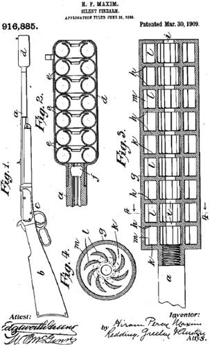
The sound of a gunshot is created by a combination of source mechanisms. The source mechanisms for the gunshot sound are a) gunpowder combustion gases flowing through the muzzle (discharge end of the firearm) and breech (an opening at the rear of the barrel where casings are ejected), b) the shock wave generated by the supersonic projectile movement, c) the wave formed by the air column ejected from the gun barrel in front of the projectile, and d) the acoustic wave generated by the collision of gun parts during the firing process (i.e. bolt carrier group)(Meinke et al. Citation2017; Selech et al. Citation2020). The gunshot sound is characterized by high-frequency (1 to 8 kHz), short-duration impulse noise that is perceived by humans as a single, loud impulse or “shot” (Murphy et al. Citation2018). When sound created by a gunshot is measured, isolation of the acoustic signals of the different source mechanisms becomes difficult (DoD 1997). Reflected signals can affect the noise level measurement if the sampling or recording periods are longer than the time interval between the primary and reflected sounds.
Most of the noise created by a shot from a firearm propagates away from the source in a spherical to hemispherical manner, depending on ground reflection, causing the sound to diminish by the inverse square law so that each doubling of the distance reduces the sound level by 6 dB (Dater Citation2014). The exception is the “crack” caused by the flight of the supersonic round which propagates forward with the flight of the bullet (Dater Citation2014). However, the forward propagation of the sonic crack does travel backward to the shooter through spherical propagation and reflections. Muzzle suppressors, therefore, primarily protect the shooter’s hearing from the expelled muzzle gas.
In the OSHA Hierarchy of Controls, engineering methods are preferred over Personal Protective Equipment (PPE) for hazard control. However, the current practice relies on PPE as the primary means of hearing protection, instead of the engineering control of a suppressor, even though firearm suppressors provide effective control for the noise hazard emanating from the muzzle. The alleged NIHL of 290,000+ claimants in ongoing multidistrict litigation (MDL) regarding the Aearo Technologies/3M Combat Arms Earplug version 2 (CAEv2) demonstrates the challenge of effective PPE use in combat situations (Roland and Rosenthal Citation2023). As a report from the Air Force Research Lab stated, “Level-dependent passive hearing protection devices can potentially provide high levels of attenuation in both continuous and impulsive noise environments. However, due to the level of noise attenuation, communication effectiveness, and situational awareness could be negatively affected” (Gallagher et al. Citation2016). This dichotomy of the prevention of NIHL and the ability to ascertain the location of incoming fire drives an imperative to cease reliance on PPE and move to reliance on muzzle noise suppression devices as an engineering control, as they allow for both hearing protection and situational awareness. Additionally, law enforcement officers have expressed concerns over the adequacy of electronic earmuffs (Murphy and Tubbs Citation2007), since law enforcement is in a similar situation of needing hearing protection, but also the ability to give verbal commands and hear responses of suspects and bystanders. In civil law enforcement situations, the use of a muzzle suppressor provides the added advantage of preventing temporary threshold shifts in hearing to suspects and bystanders, thereby allowing verbal commands to be more readily understood, which reduces the need for shouting and can aid in de-escalation situations where verbal communication is essential. We investigate if the source of the primary noise hazard changes from the muzzle to the breech of semi-automatic firearm systems as the military and law enforcement begin to adopt suppressors as engineering controls.
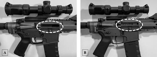
In this study, noise levels emitted from the breach of a gas-operated semi-automatic rifle (AR-15) are studied against a bolt-action control. Detailed in are the parts of an assembled AR-15 pattern rifle and illustrated in is an exploded parts view of the major components. When a cartridge is fired, the combustion gasses move the bullet down the barrel and also vent through the gas block, into the gas tube, and impinge on the gas key of the bolt-carrier group (BCG). The BCG then unlocks the bolt that holds the cartridge in the barrel and is accelerated reward ejecting the spent casing (). The spring in the buffer tube then pushes the BCG forward, picking up a new round from the magazine, placing it in the chamber, and the bolt locks in preparation for the next firing. When the BCG is in the forward and locked position, it is said to be in battery (). On a firearm, the mechanism that moves forward and back to load/eject a cartridge is known as the action. When a suppressor is used, the expellant gases are restricted from exiting the muzzle, which results in higher backpressure in the barrel. This results in more gas flow in the gas tube and by extension exiting the breech of the firearm. This increase in expellant gas at the breech may increase noise at the breech from increased gas pressure, as well as from cycling the action faster and increasing the impact of the BCG into battery and its resulting mechanical noise. The increase in gas and action velocity could increase the risk of noise-induced hearing loss (NIHL) because the breech is closer to the user’s ear than the muzzle. The muzzle is always further from the ear than the breech and commonly, the barrel is 16 inches in length, placing the muzzle that far forward of the breech, away from the ear ().
Figure 2. AR-15 pattern short-barreled rifle (SBR*) diagram (major components) with a 5-inch barrel.
*Prior to 2023 this configuration was referred to as an AR Pistol.
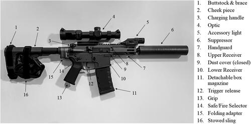
Figure 3. AR-15 pattern SBR (5-inch barrel) exploded parts diagram (major components).
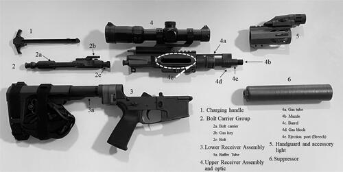
Figure 4. Gas operated bolt and carrier system from E. M. Stoner’s patent drawings. Top panel – cartridge in chamber with the bolt in battery (forward and locked position). Middle panel – bullet has left the case and propellant gasses have traveled through the gas tube and unlocked the bolt. Bottom panel – the propellant gasses have moved the bolt carrier group rearward and the case is about to be ejected from the open breech.
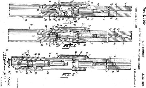
Figure 5. Detail of an AR-15 pattern firearm ejection port (breech) with the dust cover open. Panel A: bolt carrier group in the open position. Panel B: bolt carrier group in the closed and locked position, AKA “in battery.”
Suppressor manufacturers have demonstrated the ability to reduce the peak muzzle noise by approximately 17–26 dB (Murphy et al. Citation2018). However, suppressors could be creating an unexplored hazard in semi-automatic firearms usage because of increased backpressure redirects gas flow and noise through the breech. Therefore, this study aimed to investigate whether breech noise is increased by the use of a suppressor on a gas-operated semi-automatic rifle and if breech/action noise on a gas-operated semi-automatic rifle has the potential to cause NIHL even on a well-suppressed firearm since the breech/action is closer to the user’s ear.
Methods
To isolate and measure breech noise, a 12-foot tall by 16-foot wide wall was constructed to separate the muzzle noise from the breech noise. The firearms were placed on a shooting rest fastened to a sturdy shooting bench. The muzzle of the firearm to be tested was inserted through a hole in the wall with the gap between the barrel and the wall sealed with foam. Microphones were placed 1 m left of the muzzle, 15 cm right of the breech, and at the shooter’s ear position (, Test Configuration). Tests were conducted with bolt-action and semi-automatic rifles configured with and without a muzzle suppressor and with supersonic and subsonic ammunition. Tests were repeated without the wall in place.
Instrumentation
Measurements were collected with two PCB/Larson Davis (Depew, NY) model 831 sound level meters (SLM) and one Larson Davis model LxT SLM. The meters were equipped with PCB ¼-inch 377A12 microphones (sensitivity = 0.25 mV/Pa (±3 dB), 4 Hz to 20 kHz (±2 dB), Dynamic Range: (3% Distortion Limit) 182 dB re 20 µPa). The sampling frequency for all of the SLMs was 51,200 samples per second (51.2 ksps) which equates to a sampling interval of 19.5 μs. The SLMs all had a peak rise time of 30 µs (Larson Davis Citation2019). The three microphones were ¼-inch pressure, pre-polarized condenser microphones, and were connected using a ¼-inch adapter for a ½-inch pre-amplifier and a 5-pin 3-meter microphone extension cable.
Meinke et al. (Citation2016) explored the accuracy of the impulse noise measurements made with a commercial SLM compared to a laboratory-grade system. Their evaluation includes both the LxT and 831 SLMs and concluded that measurements up to 150 dB peak (dBP) SPL are adequately measured (measurements >150 dBP may be underreported due to insufficient sampling frequency), see also Kardous and Willson (Citation2004). By comparison, MIL-STD-1474E 4.7.5.2 (DoD Citation2015) specifies a minimum sampling rate of 192,000 samples per second (160,000 samples/sec. per 1474D 5.3.1.2.2 (DoD Citation1997)). Since the research focus of this work was on the quantification of noise exposure at the shooter’s ear, the measurements of greatest interest were <150 dBP, and therefore the measurement system is adequate.
The typical impulse noise that comes from a firearm is of short duration with a quick rise time. Smaller firearms produce noise impulses lasting 300–600 µs and larger calibers produce durations of ∼2 ms (Nakashima and Farinaccio Citation2015). An A-weighted scale is the standard weighting of audible frequencies and reflects the response of the human ear to noise. However, as the sound level intensifies, the frequency response of the ear flattens (Fletcher and Munson Citation1933). The flattening of the human ear loudness contours at the 100 dB threshold is better approximated by the C-weighting network. Therefore, OSHA recommends sampling using the C-weighting or a flat unweighted schema for impulse noise since it is generally above 100 dB (OSHA Citation2008). The Z scale provides a flat response across the entire frequency spectrum from 10 Hz to 20,000 Hz (OSHA Citation2011) and has a minimal effect on the rise time for the sound level meter. In comparison, A and B weighting scales are used primarily for lower to mid sound levels, making Z weighting the most efficient choice (Dater Citation2014) and providing for clear risk communication to the general public by providing unweighted peak measurements (Meinke et al. Citation2017).
When measuring impulse noise, if the microphone is pointed directly toward the source of the sound and is located within the sound field, then the recorded value could be higher due to the diffraction that will occur as the sound waves hit the microphone. This test configuration placed the microphones perpendicular to the direct noise path, which prevents pressure build-up at the microphone.
A microphone with lower sensitivity can record greater sound pressure levels. This is important because firearms create high sound pressure levels that can exceed 150 dB and damage standard microphones. The diameter of the microphone diaphragm is also important because if the microphone diameter is larger than the pulse width, then only part of the diaphragm will register the short impulse noise. If the diameter of the microphone is over ¼ inch, then the waveform can be distorted and the measured peak value becomes reduced (Rasmussen Citation2017). One disadvantage of a small microphone diameter is an increased noise floor. The instrument noise floor was obtained by placing the unit in a quiet space (LAeq 49.0 dB/Lzeq 73.1 dB) and recording eight background noise Lzpeak(max) samples of 3 s each ( Noise Floor Determination). Ear measurements of well-suppressed closed breech firearms approach the noise floor of a ¼-inch microphone.
Table 1. Noise floor determination.
Test Configuration
Peak sound pressure measurements were taken at the muzzle, shooter’s ear, and the breech. The microphone at the muzzle (reference position) was located 1.6 meters above the ground (standing shooting position from MIL-STD-1474E 4.7.3.2.1) (DoD 1997) and 1-m left of the muzzle (from the shooter’s perspective) in a commonly used reference position. The microphone representing the shooter’s left ear was located 10 cm to the rear of the breech and 15 cm off-axis to the left at optic height (∼6.35 cm above the center of the bore). The left ear position was chosen since hearing loss in right-handed shooters is most prevalent in the left ear (Moon et al. Citation2011) (Lobarinas and Le Prell Citation2014) (Meinke et al. Citation2017). Additionally, MIL-STD-1474E provides a somewhat ambiguous “Personnel location” (4.7.3.2.2.2) microphone location as shown in . Therefore, the ear location described above is offered as a repeatable reference. Finally, the microphone at the breech is located 15 cm to the right of the breech aligned with the center of the opening.
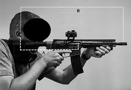
Figure 6. The ear-to-breech distance (A) of ∼15 inches (38 cm) is shorter than the ear-to-muzzle distance (B) of ∼26.5 inches (67.3 cm) on this 10.5-inch (26.7 cm) SBR. For a standard 16-inch (40.6 cm) barrel, the breech is 50% closer to the ear than is the muzzle. Note however that the shooter’s left ear Equation(8)(8)
(8) is closer to the muzzle than the right ear, but is shadowed by the skull from the breech. Note that the shooter’s cheek is in contact with the stock/cheek piece forming a cheek weld. Noise transmission to the inner ear via bone conduction was not evaluated as part of this study.
Wall construction
The muzzles of the firearms were placed through a hole in a plywood wall to separate the muzzle and breech noise signatures. A 3-inch diameter hole was cut within the wall allowing the barrel of the rifle to enter. A foam “pool noodle” was placed in the hole to act as protection so that the barrel would not strike the hole’s edge and effectively acted as a sound attenuator in the annular space. Caulking and tape were applied to all of the seams between boards to aid in attenuation. The attenuation of the wall was estimated by EquationEquation 1(1)
(1) :
(1)
(1)
Where:
NR is noise reduction,
H is the height of the wall above the muzzle in meters,
λ is the wavelength of the sound in meters, and
r is the radius to the receiving microphone in meters.
The gunshot noise spectrum is between 400 and 2,000 Hz (Meinke et al. Citation2017), which, from EquationEquation 1(1)
(1) yields an estimated attenuation of 27–34 dB. Field-testing indicated the wall attenuation was ∼30 dB.
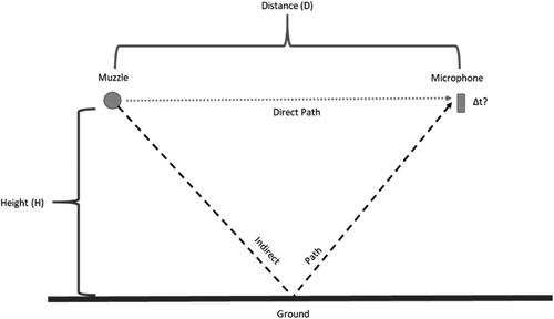
Reflection analysis
To calculate if reflections from the ground, target, or wall would affect the peak sound level measurements, noise reflection equations were used to demonstrate that the time it takes for the reflection to travel back to the microphones was long enough to allow the meters to distinguish the initial shot and reflection noise. In this study, only peak noise was considered so reflections arriving 19.5 μs after the peak noise level, being lower in intensity due to attenuation and the inverse square law, should not interfere with the peak measurement. However, allowing for a minimum of three sampling periods (58.5 μs) was the design target so that there was a distinct gap between sampling periods for the arrival of the primary and reflected impulse.
For the muzzle (reference) microphone, the indirect path for ground reflection is shown in . By dividing the distance from the muzzle to the microphone by two and then using the Pythagorean Theorem, the distance of the indirect path may be determined by EquationEquation 2(2)
(2) .
(2)
(2)
where:
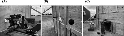
Figure 7. Test configuration.
A – Shooting rest with bolt-action firearm attached.
B – Muzzle inserted through wall with suppressor attached and muzzle microphone placement.
C – Shooting bench and wall with breech and ear microphone placement.
DInd = Indirect path distance in meters,
DDir = Direct path distance in meters,
E = Elevation of the microphone from the ground (or wall) in meters.
From these data, the difference in signal time is determined using EquationEquation 3(3)
(3) . For the ground reflection path, the second impulse arrives 6.8 ms after the main impulse. For the wall reflection path, with the muzzle extending 12 cm past the wall, the second impulse arrives 83 μs after the main impulse. Therefore, ground and wall reflections should not have interfered with peak measurements.
(3)
(3)
where:
Δt = Time difference between the arrival of the impulse sound and the reflection in seconds,
DInd = Indirect path distance in meters,
DDir = Direct path distance in meters,
C = Speed of sound in meters per second.
To determine if noise reflection from the target () affected the sound level meter result, the minimum separation distance can be calculated with EquationEquation 4(4)
(4) .
(4)
(4)
where:
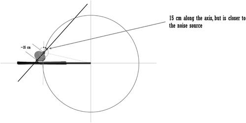
Figure 8. Ambiguity of shooter’s ear location in mil-std-1474E. After Rasmussen et al. (Citation2010) and Keim (Citation1969). The arrow indicates the microphone position described in the standard (15 cm from the ear along the axis between ears). However, this position is closer to the muzzle than the ear (indicated by the large circle). An alternative location is where the large circle intersects a 15 cm circle about the left ear, or where a perpendicular line intersects the same 15 cm circle.
Dmin is the minimum separation distance in meters between the microphone and the target,
is the velocity of the bullet in meters per second,
t is time in seconds of the desired delay (3 x sampling period)
Using three times the recording interval of the SLM (∼60 ms), c of 343 m/s, and the velocity of a subsonic 300 AAC Blackout bullet of 309.4 m/s (1,015 fps), the minimum target distance to avoid interference of peak sound measurement recordings was 9.76 meters. The shooting position for this study was placed 30 m from the backstop.
Rifles, suppressors, ammunition, and firing method
Two rifles were used during testing. The first rifle was a Ruger (Newport, NH), American Ranch model, bolt-action rifle (closed bolt design) with a 16-inch barrel chambered in 300 AAC Blackout. The second rifle was a Louthan Gunworks model LG-15, AR-15 pattern semi-automatic rifle with a 16-inch barrel also chambered in 300 AAC Blackout. The Ruger bolt action ensures that the breech is held closed after each shot while the semi-automatic AR-15 opened the breech after each shot to eject the spent brass from the ammunition cartridge. This allowed the testing plan to distinguish the difference between the control case (closed bolt) and the test case of an open breech. The suppressor used in the measurements was a Q, LLC (Dover, NH) model Full Nelson 0.30 in. caliber (7.62 mm) suppressor. The Full Nelson suppressor was selected as it has the highest sound attenuation of any 30-caliber suppressor tested by the researchers. The high performance of the Full Nelson has also been validated by Pew Science (Idriss 2022). Further, the Full Nelson suppressor uses 15 conical baffles in its design and construction which results in high back-pressure on the firearm system. This high back pressure is confirmed by the Full Nelson exhibiting Zone 7 backpressure (highest rating) in the Pew Science Omega Metric (Idriss 2022). This higher system pressure results in greater flow through the gas tube to the breach providing optimum test conditions for breech noise evaluation due to the higher quantity of expellant gas generating noise.
Supersonic and subsonic rounds were selected as test variables. American Armament Corporation (AAC), a division of Remington, developed the 300 AAC Blackout (300 BLK) Sporting Arms and Ammunition Manufacturers’ Institute (SAAMI) standard round specifically to function in M4/AR-15 actions (operating mechanism of a firearm) in both super and subsonic configurations. Remington distributes both supersonic and subsonic versions of the 300 BLK in 120 and 220 grains respectively. Remington’s Union Metallic Cartridge (UMC) type rounds were used. These rounds used the same case and primer as well as similarly constructed full metal jacket projectiles (of different masses). However, the powder charges were different.
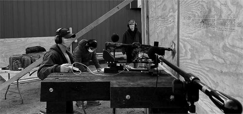
The firing was accomplished by securely mounting the rifle to a Hyskore (Middleburgh, NY) DLX Precision Shooting Rest with Remote Triggering (). This sled was equipped with springs to manage the recoil of the rifle and prevent damage to the barrel. The sled had a hydraulic trigger pulling system with a 39” tube which allows for placement of the shooter’s ear position microphone without a researcher being a source of sound reflection. The microphones were mounted on stands in fixed positions.
Figure 9. Direct and indirect sound path diagram.
Test description
The tests were conducted in two phases. The first phase, described here, addresses the research question if breech noise becomes the dominant noise hazard on a well-suppressed firearm. The test series was conducted with the wall in place and without the wall as a control. Within these two series, supersonic and subsonic rounds were used in six-shot groups in both the suppressed and unsuppressed configurations for both the open and closed bolt rifles. Once the magazine was loaded into the rifle and the rifle mounted to the rest, all six shots of that configuration were fired. While this test sequence does not allow for true repeated measures, practicality (the wall could not be constructed and removed at will) and safety dictated that firearm handling be minimized and range safety maintained (particularly with the target not in view when the wall was in place). Detailed in are the variable configurations along with the microphone positions as detailed in the previous section. In total, sixteen test configurations with six shots fired per configuration were examined. MIL-STD-1474E 4.6.2.1 states that five shots are enough to collect the necessary data, but this testing used six shots to account for the possibility of a “first-round pop” (FRP).
Table 2. Variable configuration and test results.
FRP, or first-shot noise, refers to the initial shot fired through a suppressor after it has been out of use, wherein the noise of the first shot is greater than subsequent shots. Since the suppressor is full of air containing oxygen before use, there may be an initial “pop” as the unburned powder has additional oxygen available for combustion, making the first shot louder (Silencer Shop Citation2023). FRP, to the authors’ knowledge, is not defined quantitatively in the extant literature. For this work, we provide a functional definition of FRP as a first-round impulse greater than or equal to 2 dBZ above the next highest recorded value in the test string (25.9% increase), and 3 dBZ above the group mean (41.3% increase) excluding the first shot. While the use of the Inter-Quartile Range (IRQ) is typically used for the determination of outliers i.e. >1.5xIRQ, experience has shown that this type of test may indicate an outlier that is statistically valid, but of no practical value from the perspective of human hearing. For example, IRQ analysis of the data set of 160.6, 159.1, 158.9, 159.2, 158.8, and 159.0 would indicate that 160.6 is >1.5xIRQ while only being 1.4 dBZ louder than the next highest shot and 1.3 dBZ above the mean. Given the “3 dB Rule” that states a person can only perceive a 3 dB change in apparent loudness in a dynamic environment (Bies et al. Citation2018), IRQ is of limited practical use for defining FRP. Limited information is available on how the 3 dB Rule may apply to impulse noise; the work of Johnson and Robinson (Citation1967, Citation1969) will need to be extended to better understand this issue. The Full Nelson suppressor has a reputation for negligible FRP and was selected in part for this work due to this feature ( and ).
Figure 10. Target reflection sound path.
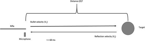
Figure 11. Hyskore DLX Precision Shooting Rest and remote trigger.
The second phase of testing explored components of breech noise that appeared in the results of the first phase of testing. To explore the hypothesis that the muzzle is not the dominant noise at the ear when the open breech rifle is well suppressed, an improvised breech suppressor was applied ( and ). The breech suppressor was an off-the-shelf brass catcher made of plastic and manufactured by Brass Goat (Sunman, IN). The Brass Goat was fitted with a foam gasket around the breech. The test was conducted in the same manner as described above section with the wall in place and using the open breech firearm, but only with supersonic ammunition. Indicated in are the variable configurations of breech suppressor only, muzzle suppressor only, breech and muzzle suppressor, and no suppressors.
Figure 12. Improvised breech suppressor.
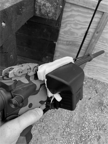
Figure 13. Microphone positions for the left ear (left side of firearm) and breech (right side of firearm).
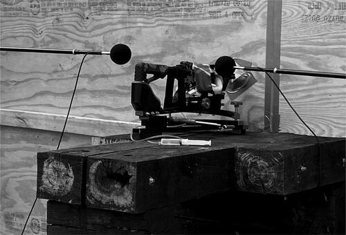
Table 3. Breech suppressor data.
To explore whether or not expelled gas at the breech is the dominant noise source at the shooter’s ear when the muzzle is well suppressed, a test was performed to characterize the noise of the action. This test used the same measurement and statistical procedure as described above using the open breech rifle but without the wall and without ammunition. An empty magazine was inserted and the charging handle retracted, thereby holding the action open. The empty magazine was then extracted and a full magazine was inserted. The bolt release was then activated to return the bolt carrier group (BCG) to battery (). Attempts to measure the return to battery sound by manually releasing the charging handle revealed high variability due to differences in release rapidity. Therefore, the bolt catch release was used for consistency. This procedure was repeated for the series of measurements with microphones placed 15 cm right of the breech and at the shooter’s ear position while the firearm was held in place on a tripod by a BOG (Columbia, MO) Deathgrip model clamp. Measurements were taken with and without the improvised breech suppressor in place. Shot four of the sample set without the breech suppressor was removed from the analysis because the charging handle impacted the researcher’s hand.
The microphones/SLMs were field-calibrated at the beginning and end of the day of testing with a Larson Davis CAL150 (114 dB @ 1,000 Hz) to ensure a drift of <1 dB. All testing was completed at a private gun range with no other impulse noise sources present.
Results
To answer the research question if breech noise becomes the dominant noise hazard on a well-suppressed firearm, the data from the field experiment were analyzed in several ways. First, data integrity was evaluated, followed by simply single variable analysis, followed by pooled analysis. Therefore, in this section, a blend of analytical methods and results of each process step are presented together for ease of understanding.
Testing validation and single variable statistical analysis
The raw results of the testing are presented in , with the data analysis procedure as follows:
Step 0 – Data collection errors
Before performing data analysis, data was reviewed for potential capture errors. Values not recorded are indicated with grey shading in . For example, the sixth shot in the Wall-Open Breech-Supersonic-Unsuppressed sample set was not recorded by any of the three instruments due to a mis-sequencing of the recording and firing procedure.
Step 1 – Outlier/FRP test
As part of the data quality evaluation, an outlier test was used to screen for either bad data capture or FRP. One value in , 150.1 dB, was identified as an FRP (Wall-Open Breech-Subsonic-Suppressed-Breech) being 2.5 dBZ higher than the next highest value in the set (33.4% increase) and 3.6 dBZ higher than the mean (51.4% increase). FPR is normally associated with the noise at the muzzle, but this test indicated that the increased backpressure of the suppressor may cause the secondary combustion gasses to exit the breech. Additionally, one low value was eliminated, the second shot in the Wall-Closed Breech-Subsonic-Unsuppressed-Breech Microphone sample set being 6.2 dBZ below the next lowest value in the set. The removed value is believed to have not been recorded during the actual shot.
Step 2 – Descriptive statistics
For each of the 48 variable and microphone configurations presented in (less the aforementioned removed values), the mean, sample standard deviation, and margin of error were calculated for the measure sound pressure levels using standard techniques. The t-distribution was used due to the small sample size (n < 30).
Step 3 – Validation that measurements taken at the muzzle with (w) and without the wall (n) are statistically similar
A test for measurement repeatability was performed using a Welch’s two-tailed difference in means t-test was performed () with Ho: µn = µw and Halt: µn ≠ µw, with the assumption of random, independent samples from two normally distributed populations where Tests were conducted at the nominal α = 0.05 level, and the 95% level of confidence intervals for the difference in means were computed, for Steps 4 through 9, using the following procedures and nomenclature:
Table 4. Statistical analysis: Summary of tests for wall effect (A–C), breech suppressor tests (D), and miscellaneous tests (E).
1 = control group,
2 = treatment group,
s = standard deviation,
n = number of samples.
P calculated using T.DIST.2T in Excel, α/2 = 0.025 and df*
Where df* is the Satterthwaite approximation, EquationEquation 7(7)
(7) .
(7)
(7)
If P < α then reject Ho: µn = µw and conclude the samples are from populations with different means.
Margin of Error for the difference in means (MoE) is calculated by EquationEquation 8(8)
(8)
(8)
(8)
where
the Excel function T.INV.2T with α/2 = 0.025 and df*
Of the eight-shot configurations, six exhibited a significantly higher mean sound pressure at the muzzle (p ≤ 0.0082) with the wall in place (average of 1.5 dBZ) compared to no wall (). This indicated the possibility of reflection effects, even though the 51.2 ksps sampling rate should have prevented this bias. Temperature effects (atmospheric or chamber) were unlikely as the wall tests were conducted in the morning and non-wall tests in the afternoon.
Step 4 – Validation that measurements taken at the ear with and without the wall were statistically different
The closed breech unsuppressed tests (super and subsonic) indicated that the wall provided ∼30 dBZ of attenuation of the muzzle blast. Hence, the measurements taken at the ear position should all have been lower when the wall was in place. The two-tailed difference in means t-test () Ho: µn = µw and Halt: µn ≠ µw at the 95% level of confidence (p < 0.05) showed that six of the eight tests indicated a significantly lower mean sound pressure at the shooter’s ear position when the wall was in place (p ≤ 0.0069) compared to no wall. The two tests that did not show a reduction in noise level at the shooter’s ear were the super- and sub-sonic tests with the suppressed open breech rifle. This is likely attributed to the increased backpressure from the suppressor restricting gas flow through the barrel and increasing flow through the gas tube into the breech, this notion is further explored in Step 7 below.
Step 5 – Validation that measurements taken at the breech with and without the wall were statistically different
The closed breech unsuppressed tests (super and subsonic) indicated that the wall provided ∼30 dBZ of attenuation. Hence, the measurements taken at the breech position should all have been lower when the wall was in place. To evaluate this effect, a two-tailed difference in means t-test was used () (Ho: µn = µw and Halt: µn ≠ µw at the 95% level of confidence (p < 0.05)) and it showed that six of the eight tests indicated a reduction in noise at the breech position when the wall was in place (p ≤ 0.0450). However, the open breech supersonic suppressed and subsonic suppressed breech microphones indicated an increase in sound level when the wall was in place. This is likely attributed to the increased backpressure from the use of the suppressor, which results in increased gas release through the breech.
Step 6 – Breech suppressor analysis
A series of tests was conducted using the breech suppressor and the results are presented in . A two-tailed test () determined that the breech suppressor did not affect the sound pressure at the muzzle (p = 0.3570). Additionally, a statistically significant (p < 0.0001) reduction in peak dBZ at the breech of 15.02 ± 1.76 dBZ was observed. However, the measurements at the ear position were on average only 0.39 dBz different, and not a statistically significant change in sound pressure (p = 0.5728). This lack of change in sound pressure at the ear when using the breech suppressor, compared to the ∼15 dBz change at the breech microphone position when the breech suppressor was used indicates that the expelled gas from the breech is not the dominant noise source at the ear and that the sound emitted from the breech is largely directional and focused away from the shooter.
Step 7 – Action noise
An additional series of action noise tests were performed and the results are found in . Consistent with the live-fire tests, the breech suppressor () did attenuate the sound coming from the breech by 3.69 ± 1.46 dBZ (p < 0.0001). Also consistent with the live-fire tests, the use of the breech suppressor did not significantly alter the sound level at the shooter’s ear (p = 0.885, increased 0.98 ± 1.36 dBZ). These two tests support the idea that gas escaping the breech is not the dominant noise source at the shooter’s ear when the muzzle is well-suppressed. The shooter’s ear experienced 123.9 ± 0.97 dBZ from the BCG returning to battery vs. 130.9 ± 0.75 dBZ when firing a live supersonic round with the wall, muzzle suppressor, and breech suppressor in place. A point of interest for hearing protection is that the BCG returning to battery is louder than firing a suppressed sub-sonic round from the bolt-action rifle, 115.9 ± 0.75 dBZ.
Table 5. Action noise: Test results (a), statistical analysis (B).
Step 8 – General observations
Additional observations are presented in . Supersonic rounds were observed to be 4.14 ± 0.96 dBZ louder than subsonic rounds. The Q Full Nelson suppressor was observed to provide 31.35 ± 0.96 dBZ of attenuation for supersonic rounds and 40.33 ± 1.50 dBZ attenuation for subsonic rounds. The subsonic attenuation of the suppressor was 4.8 dBZ greater than could be attributed to the difference in ammunition type.
Statistical analysis of design configurations
The average responses (Lzpeakmax dB) in for each of the 24 × 3 configurations were first analyzed using ANOVA methods to obtain an estimate of experimental error. For the 24 × 3 configurations of the factorial analysis, 24 represents the two states (i.e. suppressed v unsuppressed) of each of the four variables (breech type, wall presence, ammunition type, and suppressor presence), and 3 represents the three microphone test locations (ear, breech, and muzzle). The five-way interaction (wall x breech type x ammunition x suppressor x microphone) and the four-way interactions including microphone were pooled together to form the estimate of the experimental error, 1.2737 with 9 df. The 24 factorial combinations for each of the Breech and Ear microphone positions were analyzed separately using ANOVA methods and the estimate of the aforementioned error. These analyses and Tukey means comparisons were performed using the GLIMMIX procedure in SAS v9.4 software. All tests of significance were conducted at the 0.05 level and the results are presented in .
Table 6. Tests of fixed effects, (A) breech, and (B) ear. Pr(>F) is the p value of the F test statistic.
For all of the designed control variables, the one-way interactions, measured at both the breech and ear microphone positions, were significant at the selected 0.05 level of significance. In other words, the presence of the wall significantly reduced sound pressure at the ear and breech, as did the use of a muzzle suppressor. The type of breech of the firearm and the type of ammunition (super or subsonic) also have a statistically significant effect on the sound pressure level at the ear and breech microphones.
Several multi-way interactions were also statistically significant. For the microphone at the breech position, there was a significant wall by breech type by suppressor interaction (p = 0.0004), indicating that when muzzle noise is isolated (wall) then the muzzle suppressor had a statistically significant effect on the sound pressure at the breech when controlling of breech type. Additionally, there is a significant ammunition by suppressor interaction (p = 0.00075) which indicated that the suppressor effectiveness was different in super and subsonic flow regimes. For the data collected when the microphone was at the ear position, there was a significant breech type by ammunition by suppressor interaction (p = 0.0143) indicating that breech type, ammunition type, and a suppressed vs unsuppressed muzzle all contribute to the sound signature at the shooter’s ear. Additionally, there was a statistically significant interaction of the wall by suppressor and wall by breech type (p ≤ 0.0005) indicating that breech noise from a semiautomatic firearm has a greater impact on the ear than a bolt action and that a muzzle suppressor increases this effect.
Since the significant interactions were different for each of the microphone positions, the 24 combination means for each of the two microphone positions are plotted in , and significant differences among the means for each microphone position were investigated. In , lowercase letters near the plotted points indicate a group of means that are statistically the same. Therefore, if a point were labeled “ef” then any other point that is also labeled with an “e” or an “f” is statistically the same, whereas a point labeled “c” would be statistically different. In , the drawn circles labeled with upper case letters are of particular note:
Figure 14. dBz least squares means for each microphone position and configuration, mean dBz values from .
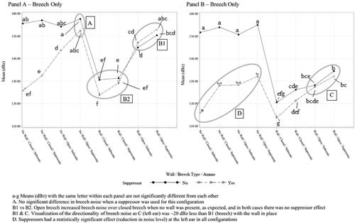
For the breech microphone position, there was not a statistically significant suppressor effect for the indicated “No Wall, Open Breech, Supersonic Ammunition” configuration, but there was a suppressor effect for all of the remaining “No Wall” configurations. This indicates that the proximity of the breech noise to the microphone (15 cm) vs its distance from the muzzle caused the two sounds to be statistically indistinct.
B1 vs B2 – Open breech configurations exhibited higher noise levels than closed breech configurations when a wall was in place, but there was no suppressor effect for either breech type when measured at the breech position.
B1 vs C – Breech noise at the left ear, C, was approximately 20 dBz less than at the breech, B.
Suppressors had a significant effect on noise at the ear position when no wall was in place. And the effect of the suppressor was greater with a closed breech and subsonic ammunition.
Discussion
This study was conducted to investigate the sound pressure levels related to the open breech of semi-automatic rifles. The different configurations consisted of the muzzles being suppressed/unsuppressed, supersonic/subsonic ammunition (Both 300 AAC Blackout), open/closed breech firearm, suppressed/unsuppressed breech, and a plywood wall through which the muzzle was placed to separate muzzle and breech noise signatures. These methods were used to reduce noise from the muzzle and action to permit quantification of the difference in peak sound pressure levels when a muzzle or breech suppressor is or is not used, and in particular, what amount of noise is attributable to the action of a semi-automatic rifle and/or breech gasses.
These findings agree with the values reported by researchers using similar configurations. Pew Science reported 130 dB 1 m left of the muzzle and 128 dB at the ear for a bolt action rifle (with an 8-inch barrel vs our 16-inch barrel) equipped with a Full Nelson suppressor and using subsonic ammunition (Discreet Ballistics vs Remington AAC USMC) (Idriss Citation2022). Our measured values of 126 dB muzzle and 117 dB ear were lower, as would be expected from the longer barrel in our test.
The results of this study indicate that, for this 300 AAC Blackout test configuration, a suppressor used on a gas-operated semi-automatic rifle may increase the noise at the breech of the firearm by approximately 1-3 dB when using subsonic ammunition and 0-1 dB when using supersonic ammunition. Additionally, the results of this study indicated that when the muzzle of a gas-operated semi-automatic rifle is nearly perfectly suppressed, the noise at the shooter’s ear was still potentially harmful, 132 ± 1 dB for supersonic ammunition and 127 ± 1 dBZ for subsonic ammunition; both of which exceed the WHO impulse noise limit for children. While ∼130 dBz impulses have potential for NIHL, the use of a suppressor greatly reduces the ∼160 dBz muzzle blast below the 140 dBc limit of the American Conference of Governmental Industrial Hygienists (ACGIH) Threshold Limit Value (TLV) and the slightly more conservative (unweighted) Occupational Safety and Health Administration (OSHA) Permissible Exposure Limit (PEL) of 140 dBz. This reduction in sound signature demonstrated that the engineering control of a suppressor is a preferred option to PPE as it eliminates issues with fit and correct direction of insertion experienced with the CAEv2, while at the same time providing the opportunity for the shooter to maintain a higher level of situational awareness. For the warfighter, the reduction in sound signature may provide added protection in making it more difficult to pinpoint the shooter’s location.
Finally, a finding of particular interest was that the dominant noise source at the shooter’s ear for a semi-automatic AR pattern firearm, once the muzzle becomes well suppressed, is the bolt carrier group returning to battery. This result holds even when the gas expelled from the breech is suppressed. This would indicate that the impact of the BCG locking into battery causes a sound wave to pass through the rear of the metal receiver and then into the atmosphere. This finding seems to support anecdotal reports from shooters that when the rifle is suppressed, they hear the action of the bolt returning to battery as being louder than the muzzle blast. Additionally, the sound level at the shooter’s ear was higher for the AR-type firearm when the bolt returns to battery by manual activation (124 ± 1 dBZ) than when shooting a subsonic well-suppressed bolt action firearm (116 ± 1 dBZ).
Limitations
This study only reviewed the breech noise as a result of a single suppressor model and a single cartridge design. Suppressors are known to vary in the backpressures produced. Therefore, breech noise may be somewhat different from suppressor to suppressor, cartridge to cartridge, and even gun to gun. Additionally, the measurements taken of the BCG returning to battery using the bolt catch release may underestimate the intensity of this sound, as the spring is not under full pressure.
Conclusions
The goal of this work was to evaluate the contribution of breech/action noise to the overall noise level delivered to a shooter’s ear to make recommendations for the continued reduction in firearm noise through engineering controls. Good safety engineering practice (and OSHA standards when applicable) requires the use of engineering controls (e.g. suppressors) before the application of administrative controls (e.g. limiting rounds shot per day), or, the method of last resort, Personal Protective Equipment (PPE) (e.g. earplugs and/or muffs). This hierarchy of controls has been turned upside down with the standard solution for firearm noise being PPE, until suppressors began to become more available about 10 years ago. However, this work indicated that hearing protection may be necessary when using semi-automatic rifles, even when well-suppressed. While a single shot is less than the 140 dB limit set by OSHA and ACGIH, the cumulative dose of multiple shots from this type of firearm necessitates PPE to prevent NIHL. Additionally, reducing sound levels at the shooter’s ear is not likely to be achieved by improved suppressor design for semi-automatic firearms. The measured value at the shooter’s ear in the semi-automatic, supersonic, suppressed configuration was 132 ± 1 dBZ. Whereas when the additional ∼30 dB of attenuation from the wall was added, the sound level at the shooter’s ear did not change, 132 ± 1 dBZ. Finally, suppressing the sound of escaping gas from the breech will have little to no impact on the sound at the shooter’s left ear. However, such a device may be desirable for certain military applications to reduce sound signature.
This work offers new insight into how the reduction in firearm noise can continue through sound engineering controls. As such, the following recommendations are offered:
More detailed quantification of return to battery sound is necessary to establish the allowable number of impulses per day as described in MIL-STD-1474E.
Since the BCG returning to battery is the dominant noise source at the shooter’s ear for well-suppressed muzzles, investigation should be made into the contribution of delivered sound energy to the ear through bone conduction via the cheek weld (where the shooter’s check is firmly placed on the cheek piece – . Initial investigations of bone conduction of firearm noise were carried out by Clavier et al. (Citation2012), but in these tests, the rifle was not in contact with the simulated and instrumented head of the test manikin.
Follow-up studies should be performed using an instrumented manikin head to establish left vs right ear effects of suppressed vs unsuppressed muzzle noise as well as for breech noise effects. First Round Pop (FRP) at the breech should also be further investigated.
Acknowledgments
The authors would like to give special thanks to Jason Louthan of https://louthangunworks.com for providing equipment, test range, and technical assistance for this work. A firearm research program would not be possible without a competent gunsmith and a safe range location. Additionally, thank you to Chris Hall who instigated this line of inquiry into suppressor effects.
Disclosure statement
No potential conflict of interest was reported by the author(s).
Data availability statement
Analytical data are available upon request from the corresponding author.
Additional information
Funding
References
- [ASA] American Suppressor Association. n.d. Hearing protection - American Suppressor Association. American Suppressor Association. [accessed 2023 Jun 21]. https://americansuppressorassociation.com/education/hearing-protection/.
- Bies DA, Hansen CH, Howard CQ. 2018. Engineering noise control, 5th ed. Boca Raton (FL): CRC Press, Taylor and Francis Group.
- Clavier O, Dietz A, Wilbur JC, Zechmann EL, Murphy WJ. 2012. Measurements of bone-conducted impulse noise from weapons using a head simulator. J Acoust Soc America. 132(3_Supplement):2014–2014. doi:10.1121/1.4755453.
- Cox M. 2020. The Marine Corps has started fielding 30,000 rifle suppressors to combat units. Military.com. https://www.military.com/daily-news/2020/12/29/marine-corps-has-started-fielding-30000-rifle-suppressors-combat-units.html.
- Dater P. 2014. Firearm sound suppression: nature and measuring of firearm sounds. http://www.larsondavis.com/ContentStore/mktg/LD_Docs/Firearm_Sound_Briefing.pdf.
- [DoD] Department of Defense. 1997. Design criteria standard: noise limits. Report No MIL-STD-1474D. https://www.dsp.dla.mil/Portals/26/Documents/Publications/Journal/160301-DSPJ-03.pdf.
- [DoD] Department of Defense. 2015. Design criteria standard: noise limits. Report No MIL-STD-1474E. https://www.dsp.dla.mil/Portals/26/Documents/Publications/Journal/160301-DSPJ-03.pdf.
- Edens A. 2018. Standard interpretation: hearing conservation program, Aug 13. Occupational Safety and Health Administration. https://www.osha.gov/laws-regs/standardinterpretations/2018-08-13.
- Elftman J. 2015. Apr. Protect your hearing. American Ferriers. [accessed 2023 Oct 4]. https://www.americanfarriers.com/articles/5925-protecting-your-hearing?v=preview#:∼:text=Prevent%20Hearing%20Lossandtext= He%20recommends%20simply%20wearing%20earmuffs,at%20the%20anvil%20or%20grinder.
- Fletcher H, Munson WA. 1933. Loudness, its definition, measurement and calculation. J Acoust Soc Am. 5(2):82–108. doi:10.1121/1.1915637.
- Gallagher H, Abouzahra NK, Swayne B. 2016. Performance assessment of the 3M Combat Arms Generation 4.0 Tactical Military Shooter’s Ear Plug. Air Force Research Laboratory Report No.: AFRL-RH-WP-TR-2016-0092. https://apps.dtic.mil/dtic/tr/fulltext/u2/1024670.pdf.
- Idriss J. 2022. Sound Signature Review (Free Version). PEW Science.
- Johnson DR, Robinson DW. 1967. The subjective evaluation of sonic bangs. Acta Acust. 18(5):241–258. https://www.ingentaconnect.com/content/dav/aaua/1967/00000018/00000005/art00003.
- Johnson DR, Robinson DW. 1969. Procedure for calculating the loudness of sonic bangs. Acta Acust. 21(6):307–318. https://www.ingentaconnect.com/contentone/dav/aaua/1969/00000021/00000006/art00003.
- Kardous CA, Willson RD. 2004. Limitations of using dosimeters in impulse noise environments. J Occup Environ Hyg. 1(7):456–462. doi:10.1080/15459620490465839.
- Keim RJ. 1969. Sensorineural hearing loss associated with firearms. Arch Otolaryngol. 90(5):581–584. doi:10.1001/archotol.1969.00770030583010.
- Larson D. 2019. Advanced sound level meter model 831. [accessed 2023 Oct 4]. http://www.larsondavis.com/docs/librariesprovider2/brochures/ld-831-sound-level-meter-brochure-(md-0438).pdf?sfvrsn=92dff851_5.
- Lobarinas E, Le Prell CG. 2014. Impulse noise produced by weapons: implications for hearing conservation. Canadian Audiologist. 1(6). https://canadianaudiologist.ca/impulse-noise-produced-by-weapons-implications-for-hearing-conservation/.
- Maxim HP, inventor. 1909. Silent firearm. United States of America patent 916,885. US Patent Office.
- Meinke DK, Flamme G, Murphy WJ, Finan D, Stewart M, Tasko S, Lankford SE. 2016. Measuring gunshots with commercial sound level meters. Paper presented at: National Hearing Conservation Association; San Diego, CA. doi:10.13140/RG.2.1.2091.8160.
- Meinke DK, Finan DS, Flamme GA, Murphy WJ, Stewart MG, Lankford JE, Tasko SM. 2017. Prevention of noise-induced hearing loss from recreational firearms. Semin Hear. 38(4):267–281. doi:10.1055/s-0037-1606323.
- Moon IS, Park SY, Park HJ, Yang HS, Hong SJ, Lee WS. 2011. Clinical characteristics of acoustic trauma caused by gunshot noise in mass rifle drills without ear protection. J Occup Environ Hyg. 8(10):618–623. doi:10.1080/15459624.2011.609013.
- Murphy WJ, Tubbs RL. 2007. Assessment of noise exposure for indoor and outdoor firing ranges. J Occup Environ Hyg. 4(9):688–697. doi:10.1080/15459620701537390.
- Murphy WJ, Flamme GA, Campbell AR, Zechmann EL, Tasko SM, Lankford JE, Meinke DK, Finan DS, Stewart MG. 2018. The reduction of gunshot noise and auditory risk through the use of firearm suppressors and low-velocity ammunition. Int J Audiol. 57(sup1):S28–S41. doi:10.1080/14992027.2017.1407459.
- Nakashima A, Farinaccio R. 2015. Review of weapon noise measurement and damage risk criteria: considerations for auditory protection and performance. Mil Med. 180(4):402–408. doi:10.7205/milmed-d-14-00204.
- [OSHA] Occupational Safety and Health Administration. 2008. Occupational noise exposure. Standard No.: 1910.95. https://www.osha.gov/laws-regs/regulations/standardnumber/1910/1910.95.
- [OSHA] Occupational Safety and Health Administration. 2011. The control of hazardous energy (lockout/tagout). Standard No.: 1910.147. https://www.osha.gov/laws-regs/regulations/standardnumber/1910/1910.147.
- [OSHA] Occupational Safety and Health Administration. 2013. OSHA Technical Manual (OTM) Section III, Chapter 5: noise. https://www.osha.gov/enforcement/directives/ted-01-00-015-5.
- Rasmussen P, Flamme G, Stewart M, Meinke D, Lankford J. 2010. Measuring recreational firearm noise. JASA. 127(3_Supplement):1794–1794. doi:10.1121/1.3384002.
- Rasmussen P. 2017. Application note: measurement of impulsive noise. https://www.grasacoustics.com/images/Measurement_of_Impulsive_Noise.pdf.
- Roland V, Rosenthal J. 2023. Seventh circuit to consider direct appeal of 3M/Aearo denying extension of stay to nondebtors. ABI Jan 2023. https://www.abi.org/abi-journal/seventh-circuit-to-consider-direct-appeal-of-3maearo-denying-extension-of-stay-to.
- Selech J, Kilikevičius A, Kilikevičienė K, Borodinas S, Matijošius J, Vainorius D, Marcinkiewicz J, Staszak Ż. 2020. Force and sound pressure sensors used for modeling the impact of the firearm with a suppressor. Appl Sci. 10(3):961. doi:10.3390/app10030961.
- Silencer Shop. 2023, Oct 4. What is first round pop? Everything you need to know. https://www.silencershop.com/blog/post/first-round-pop.
- Stewart MG. 2018. What to know about firearm suppressors and hearing loss. Leader. 23(3):18–20. doi:10.1044/leader.AEA.23032018.18.
- Stoner EM. 1960. Sept 6. Gas operated bolt and carrier system. US patent 2,951,424. https://patents.google.com/patent/US2951424A/en.
- [VBA] Veterans Benefits Administration. 2021. 2021 Annual benefits report: compensation. https://www.benefits.va.gov/REPORTS/abr/docs/2021_compensation.pdf.
- Win KN, Balalla NBP, Lwin MZ, Lai A. 2015. Noise-induced hearing loss in the police force. Saf Health Work. 6(2):134–138. doi:10.1016/j.shaw.2015.01.002.
- [WHO] World Health Organization. 1999. Guidelines for community noise. https://www.who.int/publications/i/item/a68672.