Abstract
Background and purpose Bone-anchored titanium implants have been used for anchorage of amputation prostheses for more than one and a half decades. Histo-logical and ultrastructural analyses were performed on a forearm amputation prosthesis after being in use for more than 11 years.
Material, methods and results The implant was retrieved from the ulnar bone after a fatigue fracture of the titanium implant, and was clinically stable at the time of removal. The histological findings showed a large amount of bone within the threads and a high degree of apposition of mineralized bone to the implant surface. Ultrastructural analysis of thin samples prepared by focused ion-beam microscopy revealed an electron-dense layer at the interface and direct apposition of crystalline hydroxyapatite at the implant surface.
Interpretation Our observations in this retrieval study provide a structural correlate to the functional properties and clinical results of amputation prostheses.
Titanium implants have been used clinically in dental reconstruction during the last 4 decades with excellent results (Branemark et al. Citation1977). Since then, further applications of osseointegrated titanium implants have been introduced, such as bone-anchored hearing aids, finger joint pros-theses, facial prostheses, and thumb amputation prostheses (Branemark et al. Citation2001). A more recent application is the bone-anchored amputation prosthesis for upper and lower limbs. Details of the surgical procedure have been given elsewhere (Robinson et al. Citation2004). The main advantages of direct bone-anchored skin-penetrating implants are (1) that the load is directly transferred to the skeleton instead of to the skin and soft tissues, as for the traditional socket prosthesis and, (2) that there is increased perception of the environment compared to the socket prosthesis, through osseoperception (Ysander et al. Citation2001).
In this study, we performed for the first time histological and ultrastructural analysis of a retrieved titanium implant with surrounding bone after it had been in use for 11 years as the anchorage unit for an amputation prosthesis in human bone.
Material and methods
Clinical report
A man born in 1934 underwent bilateral forearm amputations in 1977 after severe trauma. The patient was treated with osseointegrated amputation prostheses in 1993. The treatment was performed in 3 stages ( and ): surgery 1 in March 1993, surgery 2 in June 1993, and finally surgery 3 in May 1994. In November 1995, the left ulnar fixture was fractured after 18 months of use, as a result of fatigue. The fractured implant was removed and a new implant was installed the same month. (The removed implant was not the subject of this report). In May 1996, the percutaneous abutment was installed on the new implant. In November 1996, the right ulnar fixture was fractured after 41 months of use, caused by fatigue. The fractured outer part was removed (this was not the subject of this report), while the still osseointe-grated inner part of the implant was left in place. A custom-built abutment was installed on the remaining part of the implant. In 1997, the patient developed a deep infection following the operation with the custom-built abutment in the right ulnar bone; culture showed Serratia marcescens (a Gram-negative bacterium) that was sensitive to amoxycillin. By long-term treatment with antibiotics and minor revision surgery, the deep infection was controlled. In June 2004, the patient again suffered from fracture of the right ulnar implant in junction with the custom-built abutment. It was decided to remove the remaining part of the implant with a trephine after a total of 11 years of use. This removed inner part of the implant was investigated and is the subject of this report. In October 2004, a new implant was installed in the right ulnar bone. In December 2004, the percutaneous abutment was installed on the right ulnar implant. At the latest checkup (November 2006), radiographs showed good osseointegration and there were no radiographic or clinical signs of deep infection. The patient has full use of his prostheses again.
Figure 1. Clinical history.
Figure 2. The fixtures over time, with the white fixtures and abutments corresponding to the interventions and changed parts. RH, LH: right and left humerus; RR, LR: right and left radial; RU, LU: right and left ulna.
Implant
The implant was machined from pure commercial titanium (cp-Ti). After machining, the implant was cleaned ultrasonically in successive butanol and ethanol baths, and sterilization was performed by autoclaving. The implant was threaded with a diameter of 9.5 mm and a length of 70 mm.
Specimen preparation
After removal with a trephine, the specimen was fixed in formaldehyde and then dehydrated in a series of graded ethanol baths prior to embedding in LR White plastic resin (London Resin Co. Ltd., Berkshire, UK) without decalcification. The cured resin-embedded implant was divided into 2 pieces through the long axis by a carbon boride band saw (EXACT Apparatebau GmbH & Co., Norderstedt, Germany). 1 part was used to prepare a ground section stained with 1% toluidine blue for histo-logical and histomorphometric analysis using light microscopy (Donath and Breuner Citation1982). The other part was used to prepare electron-transparent transmission electron microscopy (TEM) samples using focused-ion beam (FIB) milling for ultrastructural analysis of the intact interface between the bone and titanium implant. The particular FIB used in this study was an FEI Strata DB235 equipped both with an ion gun and an electron gun (Dual beam) and also an Omniprobe in situ TEM sample lift-out system. A 100-nm-thick electron-transparent sample of the cross section of the interface was made by using an in situ lift-out method (), which has been explained elsewhere (Jarmar et al. Citation2007).
Figure 3. A. A SEM image of the Pt deposit at the site of interest. B. Trenches were cut on both sides of the Pt layer. C. The cut-out lamella was soldered to a TEM grid before final thinning. D. The final thinning was done with decreasing ion beam currents to obtain electron transparency.
Histological analysis
Qualitative and quantitative evaluation of the bone tissue surrounding the implant was performed with a light microscope connected to a personal computer. The results of the quantitative evaluation are presented as mean percentage with corresponding standard error (SE) of the bone-implant contact and the relative amount of bone within the threads throughout the whole threaded area of the implant. The qualitative analysis is presented with images.
Ultrastructural analysis
The ultrastructural analysis was done with an FEI Tecnai F30 ST TEM operated at 300 kV and equipped with a Gatan Imaging Filter. The different TEM analysis methods used were bright-field TEM (BFTEM), energy-filtered TEM (EFTEM), and high-resolution TEM (HRTEM) in order to analyze the morphology as well as the structure and composition of the interface between the implant material and the bone tissue. The samples were cooled to −172°C (with liquid N2) in a TEM cryo sample holder during analysis, in order to prevent electron beam damage to the bone tissue.
Results
Histological analysis
The inner cavity at the proximal end of the implant was dominated by trabecular bone surrounded by well-vascularized bone marrow. Few inflammatory cells were visible. The bone trabeculae had a predominantly perpendicular direction to the long axis of the implant in the middle of the cavity, while they were more aligned with the implant closer to and in contact with the surface (). The threaded outer side of the implant was dominated by lamellar cortical bone, which was remodeled with clear haversian systems surrounded by osteocytes. The threads closest to the implant fracture were dominated by soft tissue (). Many threads were completely filled with bone ().
Figure 4. A. Micrograph of the apical part of the implant. Trabecular bone is growing into the hollow apex of the implant and is also growing at the implant surface. B. Bone growth into the hollow part of the implant following the implant surface. C. This high-magnification optical micrograph shows the bone-implant contact in the hollow part of the implant.
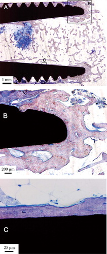
Figure 5. A. Overview of the implant fracture and the closest threads. B. A large amount of bone-implant contact within the threads closest to the implant fracture.
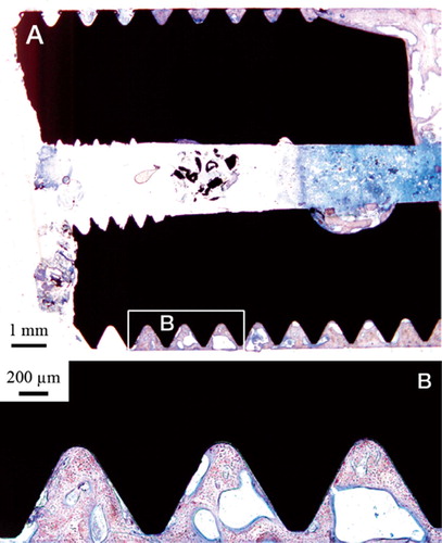
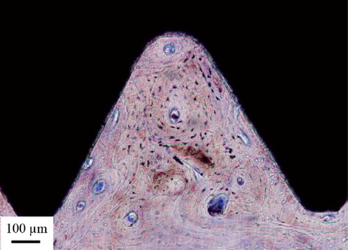
Figure 6. A thread completely filled with mature compact bone.
Histomorphometric analysis
Light-microscopic morphometry revealed a large amount of bone tissue within the threads, and in direct contact with the implant surface. An exception was the threads closest to the implant fracture zone; these were dominated by soft tissue. The values of bone implant contact (BIC) and the amount of bone within the threads were averaged over 59 threads excluding the 4 threads closest to the implant fracture, with mean values of 85% (SE 2%) and 75% (SE 4%), respectively ().
Figure 7. The distribution of bone area within threads (black bars) and bone-implant contact (gray bars) along the implant threads from fracture zone to apex. The axis est threads. B. A large amount of bone-implant contact represents the amount in percentage, within the threads closest to the implant fracture.
Ultrastructural analysis
Bright-field TEM imaging of the implant-bone interface revealed an interface zone characterized by an inner apatite layer of about 200 nm thick and an outer electron-dense layer with high diffraction contrast (). Mineralized bone was identified from the characteristic collagen banding and the randomly organized hydroxyapatite crystals. In the image series in , an element mapping by energy-filtered TEM (EFTEM) is shown. Calcium (Ca) was distributed in direct contact with the implant surface. Also, an artifact dominated by carbon (C) was seen. In the high-resolution image in , the presence of Ca at the implant surface was confirmed to be crystalline hydroxyapatite (HA). The distance between the lattice planes corresponded to the HA (002) (JCPDS Citation2005). Furthermore, an amorphous layer between the crystalline titanium grains and the hydroxyapatite indicated the presence of amorphous titanium oxide.
Figure 8. TEM bright-field image of the sample. The arrows show the apatite layer (∼200 nm) closest to the implant surface. The arrowheads show a layer with high diffraction contrast, containing HA crystals (∼200 nm). (*Artifact of preparation).
Figure 9. A. An EFTEM image of the sample generated from electrons with zero-loss energy. B. Image generated by electrons with an energy loss characteristic of titanium (Ti). C. Image generated by electrons with an energy loss characteristic of calcium (Ca). D) Image generated by electrons with an energy loss characteristic of carbon (C).
Figure 10. A high-resolution image of the interface zone where crystalline hydroxyapatite (HA) is present at the implant surface according to the bandwidth. There is an amorphous zone between the HA and the titanium, which most likely corresponds to amorphous titanium oxide.
Discussion
The first bone-anchored amputation prosthesis (femoral) based on the Brånemark concept was installed in 1990, and is still in use today. Recent studies have shown an increased quality of life for these patients compared to amputees using socket prostheses (Hagberg et al. Citation2007). This is the first report on histological and ultrastructural analysis of a similar implant after 11 years of use. The implant was clinically stable at the time of removal, and the cause of removal was mechanical failure.
The results from the histomorphometric analysis (75% bone area; 85% bone-implant contact) are in accordance with previous observations of clinically stable oral implants, retrieved after up to 16 years (79–95% bone area; 56–85% bone contact) (Sennerby et al. Citation1991). Also, it can be expected that the long-term infection in our patient, although clinically not very aggressive, may have led to some bone resorption and a reduced rate of bone contact closest to the fracture. It is surprising to find that osseointegration can work for many years despite the fact that there is chronic infection. As judged by morphological examination, retrieved, clinically well-functioning, uncemented metal arthroplasties are often associated either with a fibrous membrane or limited bone ingrowth/bone-implant contact (Cook et al. Citation1988, Fornasier et al. Citation1991, Bloebaum et al. Citation1997, Lester et al. Citation1998). On the other hand, higher apposition of bone to the implant has been observed with calcium phosphate-coated metal femoral stems: 32–78% (Bauer et al. Citation1991) and about 50% (Tonino et al. Citation1999). Taken together, our quantitative data are in agreement with the clinical observation of a stable amputation prosthesis. Given the different magnitude and pattern of loading for prostheses in the limbs and oral implants, for example, the current morphomet-ric data indicate that an equally prominent direct bone-implant contact can also be achieved in the upper extremity, thus supporting the notion that the concept of osseointegrated implants andprostheses may be expanded beyond the oral and maxillofa-cial region.
The FIB technique for TEM sample preparation of experimental implants in bone was recently introduced as a valuable tool for biomaterials research, where site-specific cross-section samples could be produced at a quality enabling high-end TEM analysis. Furthermore, the FIB sectioning was performed on undecalcified tissue with the implant left intact, thus minimizing introduction of artifacts due to the sectioning (Engqvist et al. Citation2006). This contrasts with ultramicrotomy sectioning where the tissue either has to be decalcified (Listgarten et al. Citation1992) and separated from the implant, or the bulk metal has to be removed leaving only the oxide layer (Sennerby et al. Citation1991). A carbon-rich artifact most likely originating from the early specimen preparation where the fixation, dehydration, and embedding affected the volume of the bone tissue (Lawton et al. Citation1995), was visible in the TEM images. The interface zone was composed of 3 different layers: an innermost apatite layer followed by an electron-dense layer with high diffraction contrast, and mineralized bone. Sennerby et al. (Citation1991) found 2 interpositioned layers between the implant and the normal bone—first an amorphous layer 100–400 nm in thickness, then an electron-dense mineralized zone of 50–100 nm—when analyzing retrieved oral implants. According to Linder et al. (Citation1983), there was a layer of ground substance, composed of proteoglycans and scattered calcified deposits with a thickness of 20–50 nm closest to the implant surface, then a layer of randomly distributed collagen (100–500 nm) before the normal bone tissue was seen. On the other hand, Listgarten et al. (Citation1992) found hydroxyapatite crystallites extending towards the implant surface to form an intimate contact between mineralized bone and implant, without any evidence of this non-mineralized zone when examining cp-Ti coated epoxy plugs in dog mandible. Different interfaces, partially overlapping regarding their characteristics, have thus been reported by different researchers (Linder et al. Citation1983, Sennerby et al. Citation1991, Listgarten et al. Citation1992). One likely explanation is that these alterations are due to different techniques of sample preparation, but it is also important to point out that the interface may vary along the implant surface (Sennerby et al. Citation1991). The TEM samples are small; thus, only a small part of the interface could be imaged and analyzed. However, it is important to try to describe the interface in greater detail in order for us to gain a better understanding of the osseointegration process.
This first histological and ultrastructural study on a retrieved forearm bone-anchored amputation prosthesis and surrounding tissues has shown that there was a high degree of osseointegration, with mature, mineralized, and remodeled bone in direct contact with the implant surface after 11 years. These findings, together with the absence of any adverse reactions at the interface, support the clinical observation of a stable bone-prosthesis unit.
Acknowledgments
The support from the VINNOVA VinnVäxt Program Bio-medical Development in Western Sweden, the Swedish Research Council (grant K2006–73X-09495–16-3), the Institute of Biomaterials and Cell Therapy (IBCT), the Göran Gustafsson Foundation, Doxa AB, and Integrum AB is gratefully acknowledged.
None of the authors have received any personal financial support relating to this study. However, one of the authors (RB) has commercial interests in the amputation prostheses.
Contributions of authors
PT, RB, HE, and TJ designed the study. RB performed the surgery. RB and AP gathered the patient data. TJ and LE gathered the measured data. AP, TJ, and LE performed data analysis. AP wrote the first draft.
- Bauer T W, Geesink R C, Zimmerman R, McMahon J T. Hydroxyapatite-coated femoral stems. Histological analysis of components retrieved at autopsy. J Bone Joint Surg (Am) 1991; 73(10)1439–52
- Bloebaum R D, Mihalopoulus N L, Jensen J W, Dorr L D. Postmortem analysis of bone growth into porous-coated acetabular components. J Bone Joint Surg (Am) 1997; 79(7)1013–22
- Branemark P I, Hansson B O, Adell R, Breine U, Lindstrom J, Hallen O, Ohman A. Osseointegrated implants in the treatment of the edentulous jaw. Experience from a 10-year period. Scand J Plast Reconstr Surg (Suppl) 1977; 16: 1–132
- Branemark R, Branemark P I, Rydevik B, Myers R R. Osseo-integration in skeletal reconstruction and rehabilitation: a review. J Rehabil Res Dev 2001; 38(2)175–81
- Cook S D, Thomas K A, Haddad R J, Jr. Histologic analysis of retrieved human porous-coated total joint components. Clin Orthop 1988, 234: 90–101
- Donath K, Breuner G. A method for the study of undecalci-fied bones and teeth with attached soft tissues. The Sage-Schliff (sawing and grinding) technique. J Oral Pathol 1982; 11(4)318–26
- Engqvist H, Botton G A, Couillard M, Mohammadi S, Malmstrom J, Emanuelsson L, Hermansson L, Phaneuf M W, Thomsen P. A novel tool for high-resolution transmission electron microscopy of intact interfaces between bone and metallic implants. J Biomed Mater Res A 2006; 78(1)20–4
- Fornasier V, Wright J, Seligman J. The histomorphologic and morphometric study of asymptomatic hip arthroplasty. A postmortem study. Clin Orthop 1991, 271: 272–82
- Hagberg K, Brånemark R, Gunterberg B, Rydevik B. Osseointegrated trans-femoral amputation prostheses: Prospective results of general and condition-specific quality of life in 18 patients at 2-year follow-up. Prosthet Orthot Int 2007, Accepted
- Jarmar T, Palmquist A, Branemark R, Hermansson L, Engqvist H, Thomsen P. Technique for preparation and characterization in cross-section of oral titanium implant surfaces using focused ion beam and transmission electron microscopy. J Biomed Mat Res Part A 2007, accepted
- JCPDS-International, Center for Diffraction Data-PDF file no. 09–432 (Hydroxylapatite) 2005
- Lawton D M, Oswald W B, McClure J. The biological reality of the interlacunar network in the embryonic, cartilaginous, skeleton: a thiazine dye/absolute ethanol/LR White resin protocol for visualizing the network with minimal tissue shrinkage. J Microsc 1995; 178(Pt 1)66–85
- Lester D K, Campbell P, Ehya A, Rude R K. Assessment of press-fit hip femoral components retrieved at autopsy. Orthopedics 1998; 21(1)27–33
- Linder L, Albrektsson T, Branemark P I, Hansson H A, Ivars-son B, Jonsson U, Lundstrom I. Electron microscopic analysis of the bone-titanium interface. Acta Orthop Scand 1983; 54(1)45–52
- Listgarten M A, Buser D, Steinemann S G, Donath K, Lang N P, Weber H P. Light and transmission electron microscopy of the intact interfaces between non-submerged titanium-coated epoxy resin implants and bone or gingiva. J Dent Res 1992; 71(2)364–71
- Robinson K, Brånemark R, Ward D. Future Developments: Osseointegration in Transfemoral Amputees. Atlas of amputations and limb deficiencies: Surgical, prosthetic and rehabilitation principlesThird, D Smith, J Michael, J Bowker, 2004; 673–81
- Sennerby L, Ericson L E, Thomsen P, Lekholm U, Astrand P. Structure of the bone-titanium interface in retrieved clinical oral implants. Clin Oral Implants Res 1991; 2(3)103–11
- Tonino A J, Therin M, Doyle C. Hydroxyapatite-coated femoral stems. Histology and histomorphometry around five components retrieved at post mortem. J Bone Joint Surg (Br) 1999; 81(1)148–54
- Ysander M, Branemark R, Olmarker K, Myers R R. Intra-medullary osseointegration: development of a rodent model and study of histology and neuropeptide changes around titanium implants. J Rehabil Res Dev 2001; 38(2)183–90