
 ?Mathematical formulae have been encoded as MathML and are displayed in this HTML version using MathJax in order to improve their display. Uncheck the box to turn MathJax off. This feature requires Javascript. Click on a formula to zoom.
Abstract
The super-large rectangular underpass of the Putian Railway Station, driven by the rectangular pipe-jacking method, needs to bore cross under the operational Hangzhou-Shenzhen high-speed railway in the composite stratum. This paper aims to explore the construction stability and reinforcement technology of the super-large rectangular tunnel when excavating under the operational high-speed railway in the composite stratums. Firstly, the engineering background, the construction method, and the geological conditions are introduced in detail. Then, to evaluate the stability and safety of the construction, refined numerical models and the hard-rock ratio for the super-large rectangular pipe jacking tunnel in the composite stratum are proposed, and a construction risk assessment system comprising twenty risk factors is established. After that, three schemes are employed to guarantee the construction safety of the super-large rectangular tunnel and the high-speed railway, the reinforcement effect of schemes is derived by analyzing track stress, track settlement, safety factor, and risk re-assessment results, and the optimal scheme for the present project has been obtained. Finally, hand-dug piles + D-shaped beam has been employed for the adjacent construction of the Hangzhou-Shenzhen high-speed railway, the reinforcement technology and the automatic investigation system are proposed, thus the effectiveness of the scheme has been verified.
1. Introduction
The operation mileage of China’s high-speed railway has exceeded 40,000 km, accounting for more than 2/3 of the global total (Jie et al. Citation2022). To meet the traffic demand brought by urbanization, building transportation facilities under high-speed railways is an efficient method (Yong-Sang and Byung-Hyun Citation2020; Zhang Citation2022). However, the construction of facilities adjacent to the high-speed railway always suffers difficulties due to its significant role in traffic networks and rigorous deformation requirements (Zhao et al. Citation2020; Shan et al. Citation2022).
The rectangular pipe jacking method, characterized by excellent environmental adaptability, low construction cost, better construction safety, and environmental friendliness, has been increasingly widely employed in urban tunnels (Khazaei et al. Citation2004; Cheng et al. Citation2017; Tong et al. Citation2022). However, urban tunnels at present are developing towards complicated engineering conditions, for example, tunnel projects with the abnormal section, small clear distances, super-large sections, super-long distances, super shallow burial, or complex geologies (Ong et al. Citation2022a; Transport 2022). For the pipe-jacking tunnel adjacent to the high-speed railway, therefore, how to ensure the construction safety of the pipe-jacking construction and the normal operation of the existing high-speed railway is a huge challenge (Yuan et al. Citation2020; Hong and Feng Citation2021).
To date, scholars and experts have generated instructive research on the tunnel projects adjacent to the high-speed railway. For example, based on the Nanning Rail Transit Metro Line 3 undercrossing the Liuzhou-Nanning Intercity Railway, (Qi Citation2018) explores the reliability of the reinforcement scheme of D-shape beam and rock grouting. (Lin et al. Citation2018) established the optimized risk assessment model of shield tunnels boring under the existing railway, and employed the model in the Changsha Metro Line No.1 which crosses under the Beijing-Guangzhou Railway. Through the field investigation of the double-tunnel shield crossing under the Beijing Airport Railway, (Ma et al. Citation2020) summarizes the influence of the construction parameters, surface pre-grouting method, and rock grouting measure on the deformation of the subgrade. In summary, the above research has already provided abundant and serviceable references for the construction of tunnel projects adjacent to the high-speed railway. Nevertheless, considering the various factors affecting the safety and stability of the construction in the tunnel engineering adjacent to the railway (Wang et al. Citation2019), the research of the tunnel-railway proximity construction must be carried out by relying on the specific projects.
In addition, the existing research on rectangular pipe jacking tunnels is mostly based on the assumption of the single or homogeneous stratum, while these in the composite stratum is rarely reported (Men et al. Citation2019). The composite stratums, consisting of two or more types of strata (Su et al. Citation2019; Xiao et al. Citation2019), often emerge in the southeast coastal areas of China, including the Guangzhou, Shenzhen, Changsha, Fuzhou, and Nanjing cities (Lu et al. Citation2014; He et al. Citation2021). When the shield tunnel or pipe jacking tunnel excavates in a composite stratum, the excavation direction usually encounters different types of soil layers, whose hydrological and mechanical characteristics may be dramatically different (Song et al. Citation2020). Also, the construction parameters of pipe jacking construction in the composite stratum need to be frequently adjusted, resulting in low tunneling efficiency, serious tool wear, shield machine head up, ground settlement, and other problems (Han et al. Citation2020; Song et al. Citation2022). Furthermore, if the jacking speed and silo pressure of the shield machine have not been properly controlled composite stratum, the excavation surface may lose stability, and the surrounding buildings may be seriously damaged (Dai and Hu Citation2021). In serious cases, the life and safety of the construction personnel may be severely threatened.
To sum up, at present, the construction technology of the rectangular pipe jacking in the composite stratum is still in the exploratory stage. Few studies on the construction of the super-large rectangular pipe jacking tunnel close to the high-speed railway are recorded, and even less reports on the study of combining it with composite stratum. Meanwhile, for the large cross-section rectangular tunnel, its flattening rate is lower than that of the conventional circle- or horseshoe-shaped tunnels, which may lead to more serious construction disturbances, and puts forward higher difficulties for construction impact control (Tan et al. Citation2020).
Therefore, in this paper, the construction safety and reinforcement technology of the super-large rectangular pipe jacking tunnel excavating under the high-speed railway in the composite stratum are studied by the field investigation, numerical analysis, and field monitoring. Firstly, the refined numerical model and the hard-rock ratio are proposed to evaluate the construction safety, and a construction risk assessment system comprising twenty risk factors is established. The risk grades of pipe jacking construction in the composite stratum are evaluated by using the analytic hierarchy process and fuzzy comprehensive evaluation method. After that, three schemes were adopted to guarantee the construction safety, and the optimal scheme for the present project was obtained. Finally, the optimal scheme was employed for the adjacent construction of the Hangzhou-Shenzhen high-speed railway, thus the effectiveness of the optimized scheme has been verified.
2. Research background
2.1. Engineering background
The two-way four-lane underpass, between the north and south squares of the Putian railway station, was designed to promote the traffic connection and the economic development of surrounding areas, as shown in . The total length of the East and the West underpasses is 820 and 860 m, respectively, of which about 265.6 m is constructed by the concealed excavation method. Besides, the concealed excavation section crosses under the Hangzhou-Shenzhen and the Fuzhou-Xiamen high-speed railways.
Figure 1. Project geographic location.
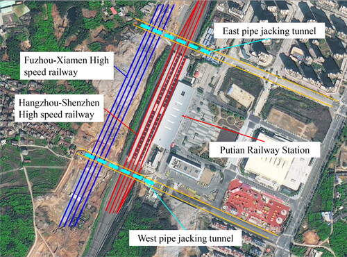
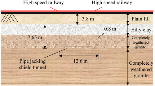
The Hangzhou-Shenzhen high-speed railway (), with a design speed of 250 km/h, is a significant railway line in operation. The adjacent length of the underpass is about 82 m, and the corresponding mileage and pipe number are K0 + 566.6-K0 + 648.8 and 77–122, respectively. The Hangzhou-Shenzhen high-speed railway has adopted three jointed and seven seamless ballasted tracks. The distance between the tunnel vault and the ballast of the railway is about 2.4 –3.8 m.
Figure 2. The Hangzhou-Shenzhen High-Speed Railway; (a) high-speed railway train; (b) tracks.

Referring to the related code, the deformation control of the Hangzhou-Shenzhen High-speed railway is highly rigorous; for instance, the deformation of the track shall not exceed 2 mm (China 2013; China 2021). Meanwhile, the construction of the super-large rectangular tunnel cannot disturb the regular operation of the train. Therefore, it is an excellent difficulty to ensure the safe operation of the Hangzhou-Shenzhen Railway in the condition of the stable construction of the super-large rectangular tunnel.
2.2. Construction method
Referring to regulations of the regional Railway Bureau, the blasting method cannot be used in the construction of the underpass high-speed railway, while the manual excavation workload cannot meet the requirements of deformation and construction period, and the workload of workers is large. Furthermore, the deformation control effect of pipe-jacking construction in the stratum is better than that of shield construction and Tunnel Boring machine (TBM) construction, and the impact of pipe-jacking construction on the overlying high-speed railway is minimal. In addition, TBM and shield construction have good economic benefits in long-distance tunnel construction, while the tunnel length of the project is only 265.6 m. Therefore, considering the construction conditions, deformation control requirements, the construction period, and the construction difficulty, the pipe jacking shield method is adopted for the super-large rectangular underpass in this project.
The Tianfei pipe jacking machine (), designed by the China Railway Engineering Equipment Group Co., Ltd., was employed in the present study. The width, height, and longitudinal length of the machine are 12.62, 7.67, and 8.055 m, respectively; the weight of the machine is about 1300 t. The Tianfei jacking machine mainly consists of the cutting mixing system, shields, driving system, slag removal and improvement system, and lubrication system. The cutting system adopts the spoke-panel composite cutter head, with an arrangement of three front and four rear; the cutting areas of cutter heads cross and cover. In theory, the excavation coverage rate can reach 95%. In addition, the blind area disposal system adopts five cutting arms and two rollers, the cutting arms are designed in the form of up three down two, and the rollers are arranged in the blind areas on both sides. The upper cutting arm can swing laterally, and the lower cutting arm can swing laterally and vertically, to realize the excavation of the blind area. The main parameters of the Tianfei pipe jacking machine are listed in .
Figure 3. The Tianfei pipe-jacking machine.
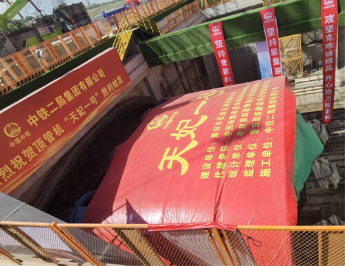
Table 1. Main parameters of the pipe jacking machine.
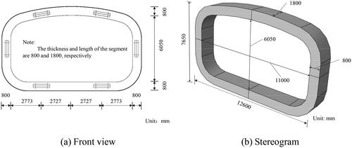
The quasi-rectangular integral reinforced concrete segment (), with the width, height, and thickness of 12.6, 7.65, and 0.8 m, is employed in the pipe-jacking tunnel. The segment’s length and weight are 1.8 m and 134.7 t, respectively. The segments with a strength grade of C50 are processed with the prefabrication method and then transported to the site by professional vehicles (MOHURD. 2011). According to the related database, this underpass is the first super-large rectangular pipe jacking project in China to cross the existing high-speed and high-speed railway to be built simultaneously.
Figure 4. Detailed dimensions of segments.
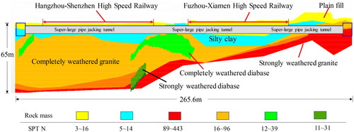
2.3. Geological condition
The pipe jacking tunnel bores through the composite stratum, as plotted in , choosing the east underpass as the example for geological description. The launching section underpass (0 –27 m): the lower and upper half of the tunnel section is moderately- and completely-weathered granite. The Fuzhou-Xiamen high-speed railway section (27–105 m): the underpass mainly tunnels through completely-weathered granite and silty clay. The Hangzhou-Shenzhen high-speed railway section (105–190 m): the tunnel mainly excavates the silty clay and a small part of completely-weathered granite. The shield receiving section (190–220 m): the tunnel mainly passes through the silty clay and a small part of completely-weathered granite. Besides, there are no adverse geological phenomena such as collapse, landslide, karst, void, and goaf in the tunnel.
Figure 5. Geological conditions.
3. Numerical simulations
3.1. Basic assumptions
The numerical simulation in the present study adopts the following assumptions:
The rock, linings, tracks, sleepers, and foundations are homogeneous and isotropic materials. The failure of rock mass and segment follows the Mohr-Coulomb criterion and the concrete damaged plasticity (i.e., CDP) model (Systèmes Citation2017), respectively.
The contact between the lining and surrounding rock during excavation is the sliding contact. The tangential stress is equal to the sliding friction, and the roles of the antifriction grout and the intermediate jacking station are ignored.
The boundary between the strata of the composite stratum is horizontal, as shown in .
Figure 6. The composite stratum.
3.2. Refined numerical model
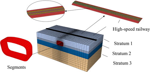
plots the refined numerical model of the super-large rectangular pipe-jacking tunnel excavating through the high-speed railway. The finite element model’s length, width, and height are 95, 54, and 40 m, respectively. The buried depth of the numerical model is 3.8 m, and the segment size is the same as the actual condition; a total of thirty joints are jacked. Given the limitation of the operating platform, a group of the Grade-II-concrete track was chosen to represent the high-speed railway. The high-speed railway and the pipe jacking tunnel are orthogonal in space. In the present study, the high-speed railway foundation stratum is embedded in the surrounding rock, and the foundation and sleeper are connected by Tie command, while the sleeper and rail are connected by 3-way damping. Besides, the tracks are assumed to be in elastic condition, and no plastic damage occurs. Moreover, considering that the high-speed railway employs a speed reduction and temporary track bypass scheme, only the self-weight of the high-speed railway is considered in refined models, and the dynamic load of the high-speed train is ignored in the present study.
Figure 7. Refined numerical model.
The Model Change algorithm is employed in the rectangular pipe jacking excavation with the displacement control method. The contact between the segment and the surrounding rock adopts the Surface-to-Surface algorithm, and the antifriction grouting is simulated by applying radial.
The simulation steps of rectangular pipe jacking tunnels are as follows: (1) Excavate the 1.8 m-long soil mass and apply 1.8 m-displacement to the first segment to simulate segment jacking. (2) Excavate the 1.8 m-long rock mass in front of the first segment, apply 1.8 m displacement to the second segment, and the 1–2 segments are jacked together. (3) Excavate the soil within 1.8 m in front of the first segment, apply 1.8 m displacement to the third segment, and the first to third ring segments are jacked together. (4) Excavate the rock mass within 1.8 m in front of the first segment, apply 1.8 m displacement to the fourth segment, and the first to fourth segments are jacked together. (5) The construction of other segments shall be carried out according to the above rule. Finally, the rectangular pipe jacking construction completes until the 30th segment has been jacked.
The bottom of the model is fully restrained, and the normal direction of the four sides is restrained during the excavation construction. In this paper, the deformation of the excavation surface is ignored, i.e. the normal displacement of the excavation surface is always restrained.
3.3. Mechanical parameters
The CDP parameters of segments are determined with the ABAQUS user manual and China Concrete Code (MOHURD. 2011), as plotted in . lists the physical and mechanical parameters of the composite stratum, sleeper, and rail by referring to related researches, survey report and laboratory test (Choo and Ong Citation2020; Peerun et al. Citation2020; Ong et al. Citation2022b). The contact parameters employed in the present study are obtained by a series of trial calculations.
Figure 8. CDP parameters; (a) Cracking strain-damage parameter in tension; (b) Inelastic strain-damage parameter in compression; (c) Yield stress-crack strain curve in tension and(d) Yield stress-crack strain curve in tension in compression.
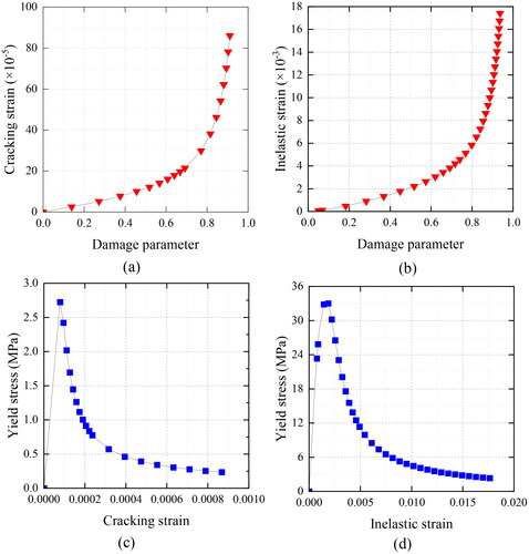
Table 2. Calculation parameters.
3.4. Monitoring system
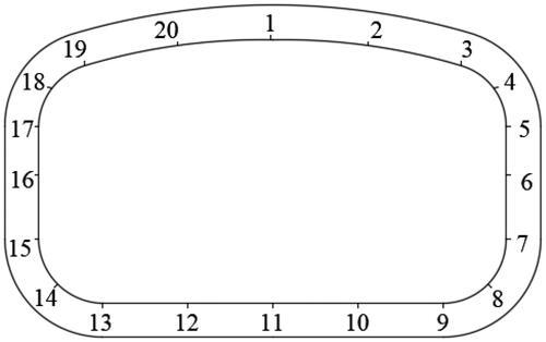
Considering the massive size of the tunnel section, a total of 20 measuring points are arranged in the rectangular pipe jacking pipe segment to monitor the stress, displacement, and safety factor, as shown in .
Figure 9. Arrangement of measuring points of displacement, stress, and safety factor.
3.5. Hard-rock ratio n
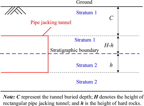
The actual conditions of composite strata may be inclined, vertical, faulted, or chaotic, yet the current research on composite strata is difficult to include the above characteristics in the same computational model, or the established model requires too many computational resources. This pipe jacking project is located in Fujian Province in southeast China, which has the typical upper-soft and lower-hard composite stratum. Therefore, for the convenience of analysis, this paper simplifies the composite strata of the project as shown in , and the hard-rock ratio n is defined in this paper, that is, the ratio of the hard rock’s height h of excavation face to tunnel height H in the composite stratum, as calculated in the formula (1). Generally, the greater the hard-rock ratio, the higher the proportion of hard rock in the composite strata.
(1)
(1)
where n represents the hard-rock ratio of the composite stratum; h represents the height of the hard rock; H represents the tunnel height of the rectangular tunnel.
Figure 10. Schematic diagram of the composite stratum.
3.6. Safety analysis of the construction
3.6.1. Deformation of the high-speed railway
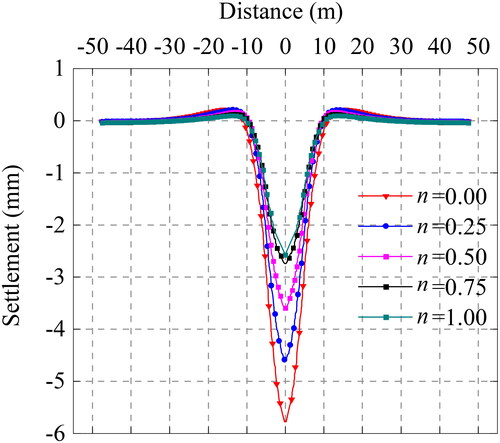
plots the track settlement of the high-speed railway after the pipe jacking, in which the coordinate origin represents the measuring point of the track directly above the vault. It could be observed that the track settlement decreases as farther away from the tunnel vault, and the maximum emerges at the coordinate origin in the horizontal direction. Besides, there is a positive relationship between the track settlement and the hard-rock ratio. The maximum track settlement is 5.78 mm when the tunnel face is composed of soft rocks (i.e. n = 0), and it increases to 4.59, 3.60, and 2.74 mm, with the n increasing to 0.25, 0.50, and 0.75, respectively. When the excavation face is full of hard rock (i.e. n = 1.0), the maximum track settlement is 2.57 mm. Referring to the related codes (China 2013; China 2021), the safety threshold of the track settlement of the high-speed railway is 2 mm. Therefore, excessive track deformation would threaten the operation of the high-speed railway, and the appropriate schemes must be employed for the reinforcement.
Figure 11. Track settlement of the high-speed railway.
3.6.2. Segment convergence
plots the segment convergence of the super-large pipe-jacking tunnel, choosing the segment directly under the high-speed railway as an example for illustration. Firstly, the vertical convergence increases sharply with the increasing excavation step and then gradually becomes stable. The larger the hard-rock ratio in the composite stratum, the more excavation steps in the sharply increasing stage. For example, the stable excavation steps for the n of 0.25 is 5, while that is 20 for the n of 0.75. It can be concluded that the pipe-jacking construction in the high-n-stratum presents less impact on the segment and finally shows better construction stability. In addition, the vertical convergence of the segment increases with the decrease of n. The maximum convergence is 13.24 mm when jacking in the soft stratum (i.e. n = 0). And it decreases to 9.57 mm、6.55 mm, and 4.82 mm when the hard-rock ratio reaches 0.25, 0.50, and 0.75, respectively. When the excavation face is full of the hard-rock ratio (i.e. n = 1.0), the vertical convergence of the segment is only 4.08 mm. The stratum with the higher n presents better integrity, which could finally decrease the convergence of the pipe jacking tunnel.
Figure 12. Segment convergence of the pipe jacking tunnel.
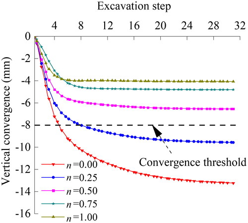
Referring to the related code (China 2021), the threshold of the segment convergence is −8 to 6 mm. When the pipe jacking tunnel excavates in the composite stratum with the n ≥ 0.5, the vertical convergence is within the threshold, while that of the n ≤ 0.5 stratum exceeds the safety limit, and practical reinforcement approaches must be adopted in such cases.
3.6.3. Safety factor
The safety factor, referring to the China tunnel code (China 2018), is chosen as the safety evaluation index in the present study, as calculated in EquationEquations (2(2)
(2) and Equation3)
(3)
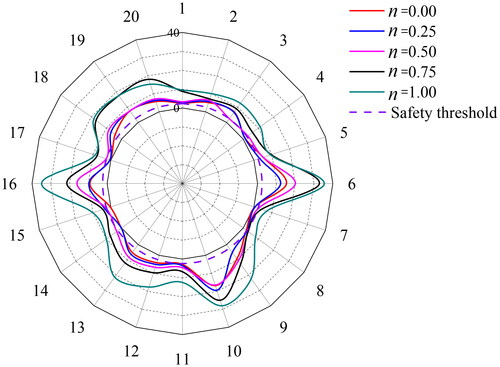
(3) . Generally, the greater the safety factor, the safer and more stable the structure. plots the safety factor of the segment when the pipe jacking tunnel construction is completed, in which the circumferential and the radial number represent the measuring point and the safety factor, respectively. The peak safety factor emerges at Point 6 and Point 16, that is, the left and right sidewalls, 35.49 and 34.87, respectively. While the minimum safety factor (i.e. the dangerous point) emerges at Point 8 and Point 14, that is, the left and right arch feet. Choosing Point 14 as an example for analysis, the minimum safety of the segment is 0.10, 0.14, 3.19, 7.32, and 9.95 when tunneling through the stratum with the n of 0.00, 0.25, 0.50, 0.75, and 1.00, respectively. When the pipe jacks through the stratum of n > 0.50, the minimum safety factor is less than the safety threshold, and the corresponding reinforcement should be considered.
(2)
(2)
(3)
(3)
where
represents safety factor;
denotes longitudinal bending coefficient;
represents influence coefficient of axial force eccentricity;
is ultimate compressive strength of concrete; b is width of tunnel section; h is thickness of section;
is ultimate tensile strength of concrete;
represents eccentricity of section.
Figure 13. Minimum safety factor of the pipe-jacking tunnel.
Note: The circumferential and the radial number represent the measuring point (i.e., ) and the minimum safety factor, respectively
3.6.4. Risk assessment for the construction
A risk assessment system for the construction of a super-large rectangular pipe jacking beneath a high-speed railway was established by integrating existing literature, expert consultation, and construction experience and data. The system comprises 20 risk factors and comprehensively evaluates the impact of seven aspects of risk factors, including hydrogeology, overlying high-speed railway, tunnel design factor, construction machinery, construction techniques, construction management, and operation and maintenance, on the risk of jacking construction under the high-speed railway, as illustrated in .
Figure 14. Risk factors of pipe-jacking construction under high-speed railway.
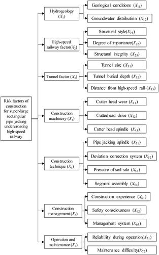
The construction risks of the super-large rectangular pipe jacking beneath a high-speed railway are classified into five levels for the likelihood, loss, and overall risk, following the relevant Chinese standards (China 2011a; China 2011b). The likelihood levels 1 to 5 indicate a gradual decrease in risk, with level 1 having the highest probability of occurrence, loss, and overall risk. The risk levels are illustrated in . To evaluate the construction risk of the super-sized rectangular pipe jacking under the high-speed railway, a panel of 10 experts with extensive engineering experience was convened. The analytic hierarchy process (AHP) and fuzzy comprehensive evaluation (FCE) method were utilized to calculate the construction risk level of the project, see for calculation results. The set of risk assessment indicators includes
(4)
(4)
Table 3. Risk classification of super-large rectangular pipe jacking under high-speed railway.
Table 4. Risk level of pipe jacking under high-speed railway construction.
The set of risk assessment levels is:
(5)
(5)
The membership degree vector is determined by expert experience. The weight vector of the first-layer risk assessment indicators is
(6)
(6)
The weight vector of the second-layer risk assessment indicators is:
(7)
(7)
Construction risk is equal to the product of probability of risk occurrence and loss, namely:
(8)
(8)
where
is the probability of risk occurrence;
is the loss caused by the risk
Referring to , when the ratio of hard rock is 0 or 0.25, the construction risk of the super-sized rectangular pipe jacking crossing under the high-speed railway is classified as Level I. When the ratio of hard rock is 0.5, 0.75, and 1, the risk levels of construction crossing under the high-speed railway are classified as Level III, IV, and IV, respectively. Meanwhile, the weight vector of the first-level evaluation indicators is W = [0.10, 0.24, 0.21, 0.12, 0.09, 0.12, 0.12], indicating that the overlying high-speed railway (X2) and tunnel design factor (X3) have a greater impact on the construction of the rectangular pipe jacking beneath the high-speed railway, and should be given special attention during construction.
3.6.5. Discussion and results
Combined with the track settlement of the high-speed railway, segment convergence, as well as the safety factor and risk assessment, the following results can be derived
As the super-large rectangular pipe jacking tunnel excavats through the composite stratum, with the increasing hard-rock ratio n, the more minor the construction disturbance of the pipe jacking construction, the better the surface settlement control effect and the better the safety of pipe segments.
When n is 0 or 0.25, the construction risk of the super-sized rectangular pipe jacking crossing under the high-speed railway is classified as Level I. When the ratio of hard rock is 0.5, 0.75, and 1, the risk levels of construction are classified as Level III, IV, and IV, respectively.
When the super-large rectangular pipe jacking tunnel excavates in the composite stratum without the high-speed railway section, reinforcement measures are not required when n ≥ 0.50 while required when n < 0.50. However, the reinforcement scheme must be employed when the super-large rectangular pipe jacking tunnels through the high-speed railway section in the composite stratum.
4. Proposed reinforcement schemes and optimization
4.1. Reinforcement scheme design
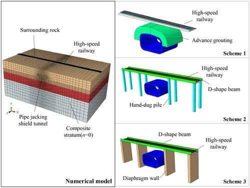
Three reinforcement schemes are proposed to decrease the construction disturbance of the super-large pipe jacking tunnel to the high-speed railway, including the advanced grouting scheme, the hand-dug piles + D-shaped beam scheme, and the diaphragm wall + D-shaped beam scheme, as listed in . In Scheme 1, the grouting range is 3 m along the radial direction and 9 m along the longitudinal direction of the rectangular tunnel. The grouting material is the inert slurry. The diameter and height of the hand-dug pile are 1.5 m and 15 m in Scheme 2. The diaphragm wall, with a thickness of 1.5 m and a height of 15 m, was employed in Scheme 3; the longitudinal depth along the tunnel is consistent with scheme 1. The D20 beam was designed in Schemes 2 and 3, tightly erected on the diaphragm wall and the hand-dug pile.
Table 5. Reinforcement schemes.
Choose the numerical simulation to study the effect of the reinforcement scheme, and the calculation models are in ; the composite stratum with the n of 0.50 is an example for illustration.
Figure 15. Numerical model of reinforcement schemes.
4.2. Reinforcement effect
The track stress, track settlement of the high-speed railway and the segments’ safety factor of super-large pipe jacking tunnels are chosen to characterize the reinforced effect of schemes in the proximity construction in the composite stratum.
4.2.1. Track stress analysis
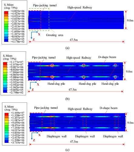
illustrates the stress distribution diagram of the refined models, and the right half of the model with a longitudinal length of 9.0 m and a hard rock ratio (n) of 0.50 is selected for display and analysis due to the bilateral symmetry. After implementing the advance grouting scheme (Scheme 1), the maximum stress on the track is 4.83 MPa, above the tunnel axis. Then, with the implementation of Scheme 2 (which involves hand-dug piles and D-shape beams), the stress on the track decreases to 3.92 MPa. However, a stress concentration of 11.77 MPa is at the connection between the hand-dug piles and D-shape beams in Scheme 2. Subsequently, with the application of diaphragm walls and D-shape beams, the stress reduces to 3.63 MPa, and stress concentration (about 14.49 MPa) is near the junction of the diagram wall and D-shape beams. From the perspective of stress, Schemes 2 and 3 are recommended for the construction of super-large rectangular pipe-jacking tunnels under operational high-speed railways in composite stratums.
Figure 16. Stress nephogram of the reinforcement models; (a) Scheme 1; (b) Scheme 2; (c) Scheme 3.
4.2.2. Track settlement analysis
illustrates the track deformation of the high-speed railway when the advanced grouting scheme, the hand-dug pile + D-shape beam scheme, and the diaphragm wall + D-shape beam scheme were adopted, the composite stratum of n = 0.50 was chosen as an example for illustrating. summarizes the track settlement of the high-speed railway with different reinforcement schemes in the composite stratum.
Figure 17. Track settlement of the high-speed railway.
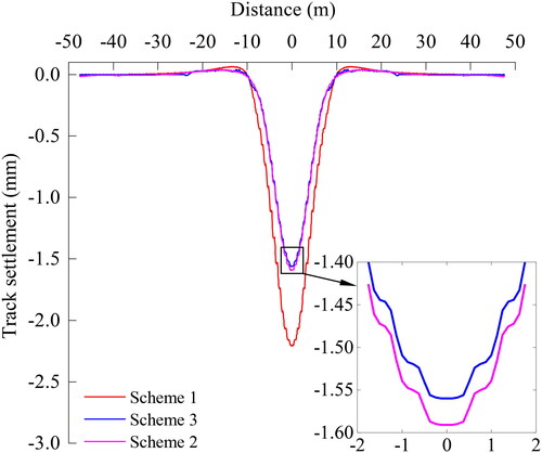
Table 6. Maximum of track settlement (Unit: mm).
When the jacking construction adopts the advanced grouting scheme, the track settlement reduces by 30.75%–48.79% compared with the tunnel without the scheme. The track settlement is greater than the safety threshold when tunneling through the composite stratum with the n of 0.75, while it is less than the safety threshold in the composite stratum with the n of 0.75 in Scheme 1. In Scheme 2, when the hand-dug pile + D-shaped beam is adopted for the jacking construction, the track settlement reduces by 48.18%–71.45%. The maximum track settlement for the construction in the stratum with the n of 0 is 1.62 mm, far less than the safety threshold (i.e. 2 mm). When the diaphragm wall + D-shaped beam is employed for the adjacent construction in Scheme 3, the track settlement decreases by 50.97%–72.49%. The track settlement decreases to 1.59 mm when excavating through the stratum with the n of 0, which is far less than the safety threshold (i.e. 2 mm).
4.2.3. Safety factor analysis
illustrates the safety factor of the super-large segment under three reinforcement schemes, choosing the composite stratum with the n of 0.5 as an instance for the exhibition. The minimum value of the safety factor under the three schemes in the composite is summarized in .
Figure 18. Minimum safety factor of pipe jacking tunnel.
Note: The circumferential and the radial number represent the measuring point (i.e., ) and the minimum safety factor, respectively
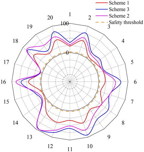
Table 7. Minimum of safety factor.
The safety factor of the pipe segment increases by 1.88–5.61 after adopting the advanced grouting in Scheme 1. The minimum safety factor of the pipe segment is 1.98 when tunneling in the composite stratum with the n of 0, which is less than the standard threshold. However, the minimum safety factor of the pipe segment is greater than the threshold when n ≥ 0.25. In Scheme 2, when the hand-dug pile + D-shaped beam is adopted, the safety factor of pipe segment increases by 9.45–21.00. No matter what the value of n is, the construction of pipe jacking shield’s pipe segment is safe and stable.
In Scheme 3, after adopting the diaphragm wall + D-shaped beam in the jacking construction, the safety factor of the pipe segment increases by 10.16–26.64. The safety factor of the pipe segment is still greater than the control threshold in the composite stratum with the n of 0, and the pipe segment of the pipe jacking construction is safe and stable.
4.2.4. Re-assessment of construction risks
The re-assessment results of construction risks are presented in . By implementing Scheme 1 (i.e. advanced grouting scheme), the risk level of the super-sized rectangular pipe jacking crossing under the high-speed railway reduces to level III-V. With the adoption of Scheme 2 (i.e. the hand-dug pile + D-shaped beam) and Scheme 3 (i.e. the diaphragm wall + D-shaped beam), the construction risk level of the super-large rectangular pipe jacking crossing under the high-speed railway changes to level IV to V. All three reinforcement schemes reduce the construction risk level of the crossing construction, but the changes are more significant with Schemes 2 and 3.
Table 8. Construction risk grade after reinforcement measures.
4.3. Scheme optimization
Combined with the track settlement and the safety factor in numerical simulations, as well as the re-assessment of construction risks, the diaphragm wall + D-shaped beam scheme has a dramatic reinforced effect, followed by the hand-dug pile + D-shaped beam scheme and advanced grouting scheme. In addition, the advanced grouting, the diaphragm wall + D-shaped beam, and the hand-dug pile + D-shaped beam could be adopted in the composite stratum with the n larger than 0.75. However, when the super-large rectangular tunnel jacking in the composite stratum with the n less than 0.75, the diaphragm wall + D-shaped beam and the hand-dug pile + D-shaped beam could be adopted.
Considering that the construction influence of the diaphragm wall construction in Scheme 2 on the existing high-speed railway is far greater than that of the hand-dug pile in Scheme 3, it is recommended to adopt the hand-dug pile + D-shaped beam in the construction of the super-large rectangular pipe jacking tunnel when jacking through the high-speed railway in operation.
5. In-situ monitoring and investigation
5.1. The reinforcement scheme for the Hangzhou-Shenzhen railway
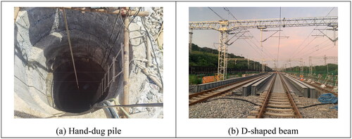
The super-large rectangular tunnel of the Putian Railway station employed the hand-dug pile + D-shaped beam scheme when jacking through the Hangzhou-Shenzhen high-speed railway, as plotted in , the D-shaped beams are firmly connected with the expanded foundation and hand-dug piles. The D-shaped beams include 24 groups of D16 beams, 23 groups of D20 beams, and 1 group of D24 beams. The diameter of the manually excavated piles (18 pieces) is 1.5 m and 1.25 m, and the pile height is 15 m. The on-site reinforcement construction is shown in .
Figure 19. Reinforcement scheme of the Hangzhou-Shenzhen Railway.
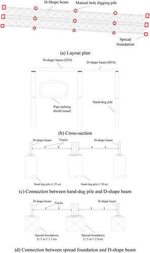
Figure 20. Site construction.
summarizes the construction technology of the super-large rectangular pipe-jacking tunnel boring through the Hangzhou-Shenzhen high-speed railway. Firstly, the hand-dug pile + D-shaped beam should be constructed before the super-large pipe jacking through under the Hangzhou-Shenzhen railway, and the upper high-speed train can operate normally. In order to reduce the construction disturbance to the high-speed railway, a 30 m-long test section is arranged before the adjacent area to optimize the construction parameter. Meanwhile, the technical and safety training shall be carried out for the personnel according to the parameters of the test section. In addition, the excavation equipment and cutting tools shall be checked and replaced to prevent accidents such as shutdown and maintenance under the station track.
Figure 21. Construction scheme of pipe jacking tunnel crossing high-speed railway.
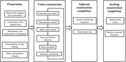
Then, in the process of pipe jacking, the speed of the Hangzhou-Shenzhen railway in that area decreases to less than 45 km/h. The earth pressure, the machine attitude, the residue improvement, the excavation state, the lubrication system, and the thrust device must be strictly controlled to ensure the information construction. Besides, the emergency plan for the boulders, bedrock, and other adverse geological conditions should be designed in advance. When the rectangular pipe jacks cross the high-speed railway successfully, monitoring of the pipe segment, the high-speed railway track, the foundation, and the surrounding structures continue to be employed with high frequency, and the track deformation should be checked and restored in time. Furthermore, the high-speed railway can resume its original speed when all parties determine that the construction impact is reduced to no impact on the operation of the high-speed railway. When the rectangular pipe-jacking construction is finished, the thixotropic slurry is replaced with the cement slurry with a volume ratio of 1:1 to consolidate the soil outside the pipe surface. Meanwhile, monitoring of the pipe jacking tunnel and the high-speed railway should be conducted until the construction disturbance is eliminated.
5.2. Monitoring system
The convergence of the pipe segment, deformations of the foundation, the D-shaped beam, the hand-dug pile, the track, and other buildings or structures should be monitored continuously and automatically when the super-large rectangular pipe shield jacks through under the Hangzhou-Shenzhen line. Meanwhile, manual measurements were also conducted during the skylight period to verify the accuracy of the data.
lists the main monitoring instruments in the present study, including the GRST-1A track geometric state monitor, the TH-STC-2000 Static Level, the Leica TS09 Electronic Total Station, and the TH-INC-T90L wireless inclinometer. Besides, the high-speed track was monitored by the track geometry monitoring system (), composed of the laser deformation radar, binocular stereo vision, and wireless data transmission system. Compared with the conventional track monitoring method, the track geometric monitoring system has characteristics of high measurement efficiency, precision, automatic monitoring, non-contact operation, all-weather work, and so on. The corresponding frequency of the monitoring system is listed in , and the double value control system is employed in the project, as shown in (China 2013; China 2021).
Figure 22. Monitoring equipment.
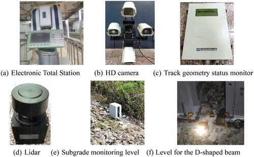
Figure 23. Track geometry monitoring system.
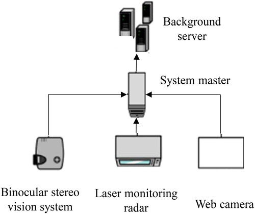
Table 9. Monitoring frequency.
Table 10. The double control value system.
5.3. Analysis of monitoring results
The track settlement curves of the Hangzhou-Shenzhen railway are plotted in , choosing Tracks 5 and 9 as examples for illustration. The maximum deformation of the pipe, structures, and beams of the field investigation are listed in , and the numerical simulation results are also given.
Figure 24. Track settlement of high-speed railway.
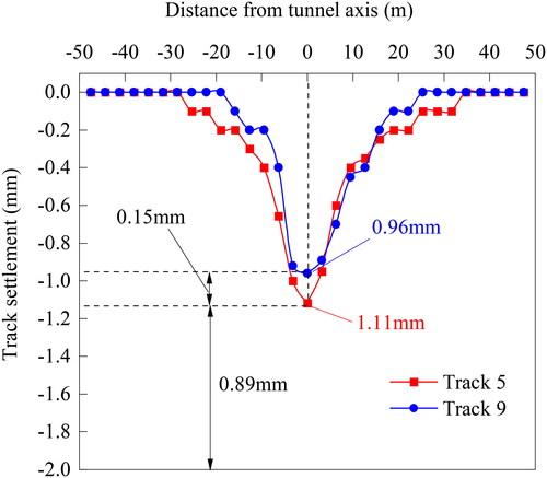
Table 11. Comparative analysis of the field investigation and numerical simulation.
Referring to the field investigation report, the super-large rectangular pipe jacking tunnel successfully excavates through the composite stratum with a reinforcement scheme of the hand-dug pile + D-shaped beam, and the operation of the Hangzhou-Shenzhen high-speed railway has not been affected. The maximum track settlement is only 1.46 mm, far less than the control threshold (i.e. 2 mm), and other indicators are within the safety control range. The numerical simulation results are slightly larger than the measured data, which can provide more safety reserves in jacking construction.
6. Discussion and conclusion
This paper investigates the stability and safety of the super-large pipe-jacking tunnel adjacent to the operational high-speed railway in the composite stratum, track settlements, safety factors, and construction risk grades are discussed. The relevant reinforcement schemes are optimized and verified through numerical simulation, risk assessment, and field investigation. Although the risk assessment for the construction of large rectangular culverts under high-speed rail using conventional methods, and corresponding risks in the operation and maintenance periods are not discussed in depth, the following conclusions can still be drawn
When the super-large rectangular pipe-jacking excavates through the normal section (i.e., without high-speed railway) in the composite stratum, reinforcement measures are not required when n ≥ 0.50, while those are required when n < 0.50. The track settlement for the underpass section (i.e., with the high-speed railway on the pipe jacking tunnel) exceeds the safety limit, the risk grade of the construction is I–IV, and the reinforcement measure must be employed.
The track stress is 4.83 MPa, the track settlement reduces by 30.75%–48.79%, the safety factor increases by 1.88–5.61, and the risk grade reduces to III-V when the advanced grouting scheme is adopted. After the diaphragm wall + D-shaped beam is employed, the track stress decreases to 3.92 MPa, the track settlement reduces by 50.97%–72.49%, the safety factor is increased by 10.16–26.64, and the risk grade reduces to IV to V. When the hand-dug pile + D-shaped beam is adopted, the track stress reduces to 3.63 MPa, the track settlement reduces by 48.18%–71.45%, the safety factor increases by 9.45–21.00, and the risk grade reduces to IV to V.
All three reinforcement schemes reduce the construction risk level of the crossing, but the changes are more significant with Schemes 2 and 3. The reinforcement effect of three adjacent construction reinforcement schemes: diaphragm wall + D-shaped beam > hand-dug pile + D-shaped beam reinforcement scheme > advanced grouting.
For the super-large rectangular pipe jacking tunnel in the composite stratum with the n ≥ 0.75, the advanced grouting scheme, the diaphragm wall + D-shaped beam scheme, or the hand-dug pile + D-shaped beam scheme can be adopted. While in the composite stratum with the n < 0.75, the diaphragm wall + D-shaped beam scheme or the hand-dug pile + D-shaped beam can be employed.
The on-site monitoring results show that the super-large rectangular pipe jacking successfully excavates through the Hangzhou-Shenzhen railway in the composite stratum after the hand-dug pile + D-shaped beam scheme is adopted. The maximum track settlement is only 1.46mm, and all monitoring indicators are within the safe range.
Acknowledgment
The author would like to thank Miss Yang Jiao of Shanxi Normal University for her valuable modification suggestions.
Disclosure statement
No potential conflict of interest was reported by the authors.
Data availability statement
The authors confirm that the data supporting the findings of this study are available within the article.
References
- Cheng LY, Ariaratnam ST, Chen SX. 2017. Analytical solution for predicting ground deformation associated with pipe jacking. J Pipeline Syst Eng Pract. 8(3)
- China MoHaU-RDotPsRo. 2011a. Code for risk management of underground works in urban rail transit. Beijing: China Architecture & Building Press.
- China MoHaU-RDotPsRo. 2013. GB 50911-2013 Code for monitoring measurement of urban rail transit engineering. Beijing: China Architecture & Building Press.
- China MoTotPsRo. 2011b. Guide for safety risk assessment of highway bridge and tunnel construction. Beijing: China Construction Industry Press.
- China MoTotPsRo. 2018. JTG 3370.1-2018 Specifications for design of highway tunnels section 1 civil engineering. Beijing: China Communications Press Co. Ltd.
- China NRAotPsRo. 2021. TB 10314-2021 Technical specification for safety monitoring of operating railway infrastructures with adjacent constructions. Beijing: China Railway Publishing House Co. Ltd.
- Choo CS, Ong DEL. 2020. Assessment of non-linear rock strength parameters for the estimation of pipe-jacking forces. Part 2. Numerical modeling. Eng Geol. 265:105405.
- Dai Z, Hu Z. 2021. Upper bound limit analysis of limit support pressure for shield excavation face in composite ground Gongcheng. Kexue Yu Jishu/Advanced Engineering Science. 53:95–102.
- Han B, Yuan D, Jin D, Li D. 2020. Analysis and predication of shield cutters wear in mixed ground Tumu Gongcheng Xuebao/China. Civil Engineering Journal. 53(137-142)and :161.
- He C, Chen F, Huang Z-H, Meng Q-J, Liu C-K, Wang S-M. 2021. Tunneling parameters and comparison of adaptability for compound strata of dual-mode shield machine. Yantu Gongcheng Xuebao/Chinese J Geotech Engng. 43:43–52.
- Hong K, Feng H. 2021. Development and thinking of tunnels and underground engineering in china in recent 2 years (from 2019 to 2020). Tunnel Construction. 41:1259–1280.
- Jie S, Yue Z, Du Y, Hu T, Sun T, Xie P. 2022. Micro-deformation monitoring technology and optimization method for the rail surface of high-speed railway operation lines with adjacent constructions. J Civil Struct Health Monit. 12(4):961–972.
- Khazaei S, Shimada H, Matsui K, Kawai T, Yotsumoto J. 2004. Over-cutting area control by using RADAR application in large diameter slurry pipe jacking method. In: ISRM International Symposium/3rd Asian Rock Mechanics Symposium (ARMS), Kyoto, JAPAN, 2004 Nov 30-Dec 02 2004. p. 633–638.
- Lin D, Mingfeng L, Cao H, Li Y. 2018. Study on construction risk of shield tunnel under-passing existing railway by fuzzy comprehensive evaluation. Journal of Railway Science and Engineering. 15:1347–1355.
- Lu H, Zhuo F, Bai Y, Li Q. 2014. Research on key techniques of shield construction in mixed ground. In: International Conference on Advances in Materials Science and Information Technologies in Industry (AMSITI), Xian, PEOPLES R China, 2014 Jan 11-12 2014. Applied Mechanics and Materials. p. 3482–3488.
- Ma W, Yang C, Peng H, Bai Y, Cheng L, Gao L, Liu Z. 2020. Settlement control on retaining wall embankment affected by underneath traversing large-diameter slurry shield tunnels Hunan Daxue Xuebao. J Hunan Univ Nat Sci. 47:44–53.
- Men Y, Wang Y, Zhou J, Liao S, Zhang K. 2019. Measurement and analysis on EPB shield machine tunneling efficiency in Jinan composite stratum. Tumu Gongcheng Xuebao/China Civil Engng J. 52:110–119.
- MOHURD. 2011. Code for design of concrete structures. Beijing: China Construction Industry Press.
- Ong DEL, Barla M, Cheng JW-C, Choo CS, Sun M, Peerun MI. 2022a. Complex soil–pipe interaction: challenges in Geological Characterization and Construction. In: Ong DEL, Barla M, Cheng JW-C, Choo. CS, Sun M, Peerun MI, editors. Sustainable pipe jacking technology in the urban environment: recent advances and innovations. Singapore: Springer Singapore; p. 43–101.
- Ong DEL, Jong SC, Cheng WC. 2022b. Ground and groundwater responses due to shaft excavation in organic soils. J Geotech Geoenviron Eng. 148(8)
- Peerun MI, Ong DEL, Choo CS, Cheng WC. 2020. Effect of interparticle behavior on the development of soil arching in soil-structure interaction. Tunnelling Underground Space Technol. 106:103610.
- Qi Y. 2018. Research on ground settlement control and ground stabilization while shield underneath pass existing railway track. Chinese Journal of Underground Space and Engineering. 14:819–827.
- Shan Y, Xiao W, Xiang K, Wang B, Zhou S. 2022. Semi-automatic construction of pile-supported subgrade adjacent to existing railway. Autom Constr. 134:104085.
- Song T, Liu C, Chen F, Xu Y, Wang S, He C. 2022. Research on the selection and tunneling adaptability of dual-mode shield/TBM in. Metro Tunnel J Railway Engng Society. 39:107–113.
- Song Y, Li A, Wang W-Y, Du C-S, Zhang D, Fu X-X. 2020. Research and application of mud proportioning optimization of slurry balance shield in mudstone and gravel composite stratum. Yantu Lixue/Rock Soil Mech. 41(4054–4062):4072.
- Su A, Wang S-M, He C, Lu D-Y, Fang R-Q. 2019. Disease characteristics and causes analysis of segments of shield tunnels in composite stratum during construction. Yantu Gongcheng Xuebao/Chinese J Geotech Engng. 41:683–692.
- Systèmes D. 2017. Dassault Systèmes 2017 User Assistance. https://help.3ds.com/HelpProductsDS.aspx. 2017
- Tan Z, Li Z, Tang W, Chen X, Duan J. 2020. Research on stress characteristics of segment structure during the construction of the large-diameter shield tunnel and cross-passage. Symmetry-Basel. 12(8):1246.
- Tong L, Zhou H, Shen H, Liu H. 2022. A complex variable solution for shallow rectangular tunnel in semi-infinite plane. J Eng Mech. 148(4)
- Transport EDoCJoHa. 2022. Review on China’s traffic tunnel engineering research: 2022. China Journal of Highway and Transport. 35:1–40.
- Wang H, Liu J, Zhang L, Iop. 2019. The Research and Control Measures of the Influence on the Complicated tie-line and the Bridge under the Shield Tunnel. In: 5th International Conference on Energy Materials and Environment Engineering (ICEMEE), Kuala Lumpur, MALAYSIA, 2019 Apr 12-14 2019. IOP Conference Series-Earth and Environmental Science.
- Xiao M, Feng K, Li C, Sun W. 2019. A method for calculating the surrounding rock pressure of shield tunnels in compound strata Yanshilixue Yu Gongcheng. Xuebao/Chinese Journal of Rock Mechanics and Engineering. 38:1836–1847.
- Yong-Sang L, Byung-Hyun C. 2020. Comparison of high-speed railway in east asia focusing on Korea. China Japan J Korean Society Railway. 23:895–905.
- Yuan Y, Xu Y-S, Arulrajah A, Yuan D-J. 2020. Ground response due to construction of shallow pipe-jacked tunnels in sandy soil: laboratory investigation. J Test Eval. 48(5):20170217.
- Zhang F. 2022. Stability analysis of construction process of new tunnel passing through high-speed railway. Foundation Journal of Railway Engineering Society. 39:53–58, 79.
- Zhao B, Wang X, Zhang C, Li W, Abbassi R, Chen K. 2020. Structural integrity assessment of shield tunnel crossing of a railway bridge using orthogonal experimental design. Eng Fail Anal. 114:104594.