
Abstract
Hybrid scaffolds prepared by blend electrospinning of Polycaprolactone and Pluronic solution benefit from enhanced fiber hydrophilicity and may offer satisfactory cell attachment and proliferation. To improve hybrid scaffold wettability and water swelling ratio, adequate amount of hydrophilic polymer is required; though this amount is limited by fiber surface enrichment of Pluronic and cannot be exceeded without affecting the scaffold mechanical properties. To overcome this problem, a routine blend electrospinning setup was modified by exposing the blend solution to water in order to attract Pluronic chains toward the surface of the charged jet. Morphology of scaffolds produced by the routine blend electrospinning and modified method was studied. A 50 nm thick Pluronic layer with linty appearance on the surface of the fibers fabricated by the modified method was detected. Drug-loaded fibers from modified method showed a moderate initial burst and then a prolonged release period while an abnormal two-stage phased release profile was observed for the routine blend method. The latter was associated to Pluronic/drug accumulations within the fibers fabricated by the routine method which resulted in fiber disintegration and a subsequent second burst release.
Introduction
Polycaprolactone (PCL) has been extensively used in biomedical application because of its good biocompatibility, mechanical strength, and biodegradability (Neppalli et al. Citation2010, Van der Schueren et al. Citation2011, Venugopal et al. Citation2005). Alas, hydrophobic nature of PCL limits its use in several biomedical applications (Arcana et al. Citation2010, Dash and Konkimalla Citation2012). Scaffold surface properties such as chemical functionalities, charge and wettability have been shown to be important factors which determine cell fate and behavior during tissue formation (Akkas et al. Citation2013, Arima and Iwata Citation2007). Therefore, fabrication of hydrophilized scaffolds has been extensively studied (Oh and Lee Citation2013, Song and Mano Citation2013).
Among these investigations, bulk blending of PCL based electrospun fibers with hydrophilic polymers proved to be most efficient for achieving a hydrophilized scaffold in comparison with other approaches such as plasma treatment which only modifies the surface of the substrate or surface grafting which carries the risk of the residual chemical reagents (de Valence et al. Citation2013, Kim et al. Citation2013, Sun et al. Citation2004). However, poor miscibility of hydrophilic polymers with PCL in non-aqueous solvents and the leakage of hydrophilic polymer from the blend while immersed in aqueous media, limits the application of blend electrospinning (Oh and Lee Citation2013). Therefore, another approach has been adopted to overcome the miscibility problem, using Poloxamer, a copolymer of polyethylene oxide-b–polypropylene oxide-b–polyethylene oxide (PEO−PPO−PEO), commercially known as Pluronic. The surfactant property of Pluronic stems from its amphiphilic characteristic, thus Pluronic type copolymers can interact with hydrophobic substrates as well as biological membranes (Hunt et al. Citation2014). Molecular assemblies of Pluronic, known as myelin, form when non-aqueous Pluronic solution comes into contact with water (Fukamachi et al. Citation2015). The Pluronic solvent should be immiscible with water, otherwise reassembly would not happen. This mucus-like, naked eye visible bilayer of agglomerated Pluronic micelles is highly stable at the interface between water and the Pluronic solution and effectively hinders the Pluronic chain diffusion into the aqueous phase.
The logic behind using a copolymer with both hydrophilic and hydrophobic blocks is to maintain the favorable interactions between main polymer hydrophobic chains and PPO segments of Pluronic in order to achieve satisfactory phase mixing while the PEO segments improve surface wettability. This idea has been proven to be successful in electrospinning and electro spraying of hydrophobic polymers in blend with low concentrations of Pluronic in terms of achieving superhydrophilic substrates (Hu et al. Citation2015, Seth and Katti Citation2012). Kurusu et al. achieved superhydrophilic mats of linear triblock copolymer styrene-b-ethylenebutylene-b-styrene (SEBS) by blending it with Pluronic F127 at concentrations up to 20 wt% (Kurusu and Demarquette Citation2015). Higher concentrations of Pluronic resulted in unstable electrospinning process and heterogeneous mats.
During the blend electrospinning process, fiber surface enrichment of hydrophilic polymer (FSEoHP) is an important factor which determines the weight percentage of excess hydrophilic polymer resides in the fiber bulk. Exceeding from certain amounts, this percentage jeopardize the mechanical properties of blended scaffold, especially when in contact with water. In other words, when FSEoHP is low, hydrophilic polymer most likely segregates from hydrophobic polymer and accumulates inside the electrospun fiber; therefore, a heterogeneous structure forms. The latter causes fast fiber disintegration while immersed in water. Assuming that the hydrophobic polymer in the blended fiber provides the mechanical properties; higher the value of FSEoHP, closer the decline of scaffold mechanical properties to the time frame of fiber’s hydrophobic part degradation (biodegradation). Vasita et al. (Citation2010) mentioned FSEoHP was reached for Pluronic F108 with no more than 0.5 wt% in blend electrospinning with PLGA. Shi et al. (Citation2008) studied the Pluronic F127 structure at molecular level in blend with polyethersulfone (PES). The hydrophobicity of air which causes the unfavorable interactions between air molecules and PEO blocks of Pluronic F127 and subsequently confines them within the bulk of the solution, has been held responsible for insufficient surface coverage of PES thin films with hydrophilic polymer, even at low concentrations of Pluronic F127 (lower than 5 wt%). Recently, electrospun mats of PCL blended with different concentrations of Pluronic P123 (P123) were prepared by Mirhosseini and coworkers (Mirhosseini et al. Citation2016). Proposing a new method, they estimated the value of FSEoHP using DSC data. The results indicated that this value remains constant for P123 concentrations higher than 15 wt% in blend. During the electrospinning process, charged jet of polymer solution travels a considerable distance through air before reaching the collector. The phenomenon explained by Shi and Vasita and experienced by Mirhosseini and others in which air hydrophobicity lowers the extent of Pluronic on the surface of the developing charged jet is a major setback for hydrophilic–hydrophobic polymers blend electrospinning due to the increased amount of hydrophilic polymer in the bulk and the subsequent phase separation. Furthermore, hydrophilicity of fiber and its morphology has a drastic effect on the drug delivery potentiality of the resulted fibrous mat. Cui et al. (Citation2006) studied the effect of polylactide fibers wetting capability on the subsequent drug release profile. They showed that the considerable hydrophobicity of electrospun fibers resulted in delayed water penetration into the scaffold. In another approach, Wu and coworkers, tuned the extent of nanopores on polylactide fibers by controlling the competition between solvent evaporation and phase separation during the electrospinning process and studied the antibiotic drug release from the electrospun fibers. They concluded that fiber nanotopography can modulate the cumulative drug release (Wu et al. Citation2015). Recently, Hu et al. (Citation2015) added the Pluronic F108 as surfactant to the electrospinning solution of PCL/bovine serum albumin (BSA) in order to increase the electrospun scaffold wettability and promote the drug penetration and release.
The aim of this work is to overcome the limits of FSEoHP in routine blend (RB) electrospinning. In our previous study, using molecular dynamic simulation, it has been concluded that the water layer selectively attracts P123 chains from the PCL-P123 blend through electrostatic interactions between P123 PEO segments and water molecules (hydrogen bonding) (Mirhosseini et al. Citation2016). Furthermore, interlayer of myelin (composed of P123 assembled chains) drastically impedes molecular diffusion between phases. Therefore, considering these assumptions, a straightforward method with reproducible results is proposed here using the exposure of PCL-P123 blend to water during electrospinning and named surfactant assisted water exposed (SAWE) electrospinning. In this article, morphology, surface composition, water uptake and contact angle of the resulted fibers from SAWE is compared with that of RB method. Furthermore, to compare the effects of these two methods on the drug release capability of electrospun fibers, diphenhydramine hydrochloride (DPH), a drug with antihistaminic activity and anticholinergic effect which belongs to the class of ethanolamine H1 receptor antagonist, was chosen as a model drug and added to the polymer solutions for electrospinning (SAWED and RBD drug loaded scaffolds). Finally, in vitro drug release from SAWED and RBD has been investigated and the results were fitted with the Weibull, Peppas and modified Korsmeyer–Peppas models to study the release mechanism.
Materials and methods
Materials
PCL (Mw = 80000), triblock copolymer P123 (Mn = 5800, 70/40 (PPO/PEO) monomer ratio) and diphenhydramine hydrochloride (DPH) were procured from Sigma Aldrich (St. Louis, MO). Deionized (DI) water and chloroform employed as immiscible solvents for electrospinning were purchased from Merck and used as received.
Electrospinning
Polymer solutions for both methods were prepared at fixed concentration of 18 wt% by dissolving the mixture of PCL and P123 in chloroform at 0.0725 mole ratio at room temperature and magnetically stirred until a clear solution was obtained (the mass ratio of PCL/P123 was 50/50). Moreover, neat PCL solution of 9 wt% concentration was obtained. Solutions containing drug was prepared with the addition of 1 wt% DPH to the blends of PCL-P123. Electrospinning process was selected to fabricate scaffolds with a set-up consisted of a high voltage supply, a syringe pump and a collector. Electrospun scaffolds of RB, RBD (from solution containing DPH) and neat PCL were prepared following a procedure described elsewhere (Mirhosseini et al. Citation2016). A slight adjustment to the electrospinning setup was carried out for the SAWE and SAWED (from solution containing DPH) method by adding a parallel DI water feed. In this method, polymer solution and DI water meet up using a simple 1 cm 3-way PE pipe connector and course a distance together (exposure distance) before reaching the 22 gauge needle (. The mass flow rate was 1.4 ml/h, and 1.2 kV/cm electric field was applied (). Scaffolds were collected on aluminum foil and placed in vacuum drying chamber at room temperature to remove the residual solvent.
Figure 1. Schematic illustration of SAWE electrospinning method.
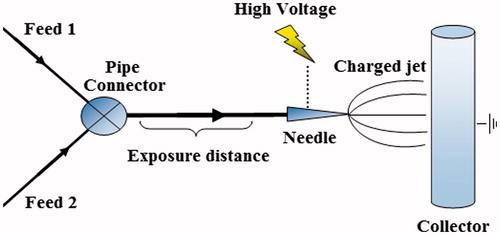
Table 1. Electrospinning process parameters.
Scaffolds characterization
Scanning electron microscopy (SEM, SERON AIS-2100, South Korea) was applied to investigate the morphology of the electrospun scaffolds using 15 kV accelerating voltage. A sputter coater was used to coat samples with gold for SEM imaging. Approximately 250 fibers were selected from SEM images of samples to analyze the average fiber diameter and corresponding size distribution using image analyzer software (Image J, developed by the National Institute of Health, Bethesda, MD). Transmission electron microscope (TEM, Zeiss EM10C), was used for detailed inspection of fibers morphology with an accelerating voltage of 80 kV. ATR-FTIR spectroscopy with 45 degree ZnSe crystal (Nexus 670 spectrometer, Thermo Nicolet, USA) was used to evaluate samples surface chemical composition in a range of 4000–600 cm−1. Water contact angle test was performed using a commercial drop shape analysis system (Data Physics OCA-15 plus, equipped with CCD camera and imaging software) to determine the extent of samples hydrophilicity. Swelling ratio test was used to evaluate scaffolds water uptake capacity. Accurately weighed (Wdry) 2 × 2 cm electrospun meshes were prepared from scaffolds and submerged in water. At different time intervals (spanned for 100 h) meshes were pulled out, the extra water removed and weighed (Wwet). The following equation was used to calculate swelling ratio percentage:
(1)
In vitro drug release
Drug release study was accomplished by a UV visible spectrophotometer (Milton Roy Spectronic 60). Before measuring samples concentration, the apparatus was calibrated by drug solutions of 100, 200, 300 and 500 ppm. For In vitro drug release, dissolution media was prepared by immersing 0.5 g of the electrospun scaffolds in 100 ml of the pH 7.4 buffer solution (PBS buffer) which kept at 37 °C (static release). At selected time intervals, 4 ml of the release media was pulled out and to maintain a constant volume, the same amount of fresh buffer solution was added back. For all DPH concentration measurements, peak at 258 nm was selected. Release data were recalculated cumulatively using the following relation (Emami et al. Citation2011).
(2)
where cumulative concentration of nth sample was denoted by C'n (mg/l), Cn and Cn - 1 were obtained from raw DPH concentration measurements of nth and (n-1)th samples (mg/l) and finally VR and VP were volumes of release media and the drawn sample (ml), respectively. Moreover, different theoretical models were selected and fitted to cumulative release data in order to evaluate drug release kinetics from SAWED and RBD. These models are mainly applicable to drug release from cylindrical shapes (e.g. fibers). Peppas model can be described by the following equation (Peppas Citation1985):
(3)
Korsmeyer–Peppas model is an adjustment to previous model (Kim and Fassihi Citation1997):
(4)
Weibull model can be presented by the following equation (Papadopoulou et al. Citation2006):
(5)
where structural characteristics determine the k component and b is the extent of burst release. In Weibull model, β depicts the specific surface area of carrier. Both Peppas and modified Korsmeyer–Peppas models express the release mechanism with their exponent of time. However, mentioned parameter characterizes the mass transport of the drug delivery medium in Weibull model. The fraction of drug release at time t (
) can be calculated by the assumption of total-loaded drug into the scaffold with respects to its weight. Mean of three measurements (n = 3) was selected to express the results and standard deviation was represented by error bars.
Results and discussions
Scanning electron microscopy
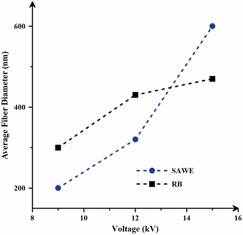
shows SEM images of SAWE and RB scaffolds at different voltages of electrospinning process. At low voltages (9 kV), the formation of beads on fibers is evident for both samples due to viscosity repulsion of polymeric solution () (Valizadeh et al. Citation2016). Morphological defects vanish at 12 kV applied voltage and smooth cylindrical fibers with no evidence of water droplets (for SAWE scaffold) appear (). However, at higher voltages, fiber merging happens (). The effect of voltage on the average fiber diameter of SAWE and RB is presented in . Because of the nonionic properties of electrospun solution, increase in voltage can promote the electrospinning ability of the blend. This promotion causes the charged jet to increase in mass during electrospinning and therefore, the resulted wet fibers (as spun fibers) are subjected to diffusion. Due to the presence of water on electrospun charged jet, the probability of fiber diffusion which leads to higher values of average fiber diameter is particularly become more pronounced for SAWE fibers. Both scaffolds have perfect fiber morphology and reasonable average fiber diameter at 12 kV of the applied voltage and therefore, this condition was chosen for the next runs.
Figure 2. Effect of voltage on SAWE and RB fiber morphologies at constant tip to collector distance (10 cm) and flow rate (1.4 mL/h): (a) 9, (b) 12 and (c) 15 kV.
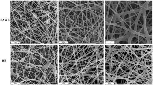
Figure 3. Effect of voltage on SAWE and RB average fiber diameter.
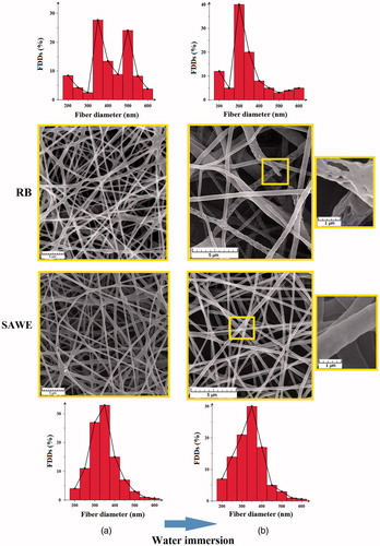
Fiber wettability and scaffold integrity play an important role on electrospun membrane applicability in tissue engineering-related purposes especially for cell attachment and proliferation (Ahmadi-Aghkand et al. Citation2015). In order to evaluate the stability of the scaffolds produced by RB and SAWE methods in aqueous media, fiber diameter distributions (FDDs) of the corresponding SEM images before and after water immersion were obtained (. According to the results, fibers prepared by RB method showed a bimodal diameter distribution (). Electrospinning solutions of PCL with low conductivity usually yield non uniform FDD and this count as an intrinsic quality of electrospun PCL scaffolds (Gharaei et al. Citation2016). Another competing factor is blend miscibility which has a dominant role on determining FDD modality. At high concentrations of P123, miscibility of blend decreases and therefore fiber characteristics diverge from neat PCL fibrous membrane which contradicts with the resulted RB FDD. During blend electrospinning, the chaotic nature of high voltage electric field may fabricate fibers with both neat and blended composition. Combining this assumption with blend miscibility, the bimodal characteristic of RB FDD can be explained. Moreover, SAWE FDD is unimodal which may contributes to the enhanced blend miscibility. The 500 nm peak from FDD diagram of as-spun RB scaffold vanishes after water immersion which suggests fragmentation of the blended fibers (). P123 accumulations within fibers, which is a direct result of negligible FSEoHP value in RB method, can rapidly leach from fibers and dissolve (micellize) in water; therefore, eliminating the integrity of the electrospun fibers. Change in SAWE FDD after water immersion is minute; a vital requirement for tissue engineering applications.
Figure 4. SEM images and corresponding FDDs of SAWE and RB (a) before and (b) after water immersion for 72 h.
Transmission electron microscopy
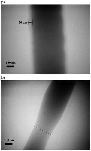
RB and SAWE TEM images are presented in . Transparency in polymeric fiber TEM images can be related to polymer electron density as well as fiber diameter. From the TEM image of RB fibers, accumulations of P123 within fibers can be deduced (, bright region). A suspected fiber thinning is observable at the position of accumulations due to the P123 short chains which reduces local viscosity and causes fiber stretching. This thinned area becomes a weak spot of the RB scaffold and is in line with the results of SEM images of RB fibers after water immersion. There, fiber deformation was happened as a result of P123 leach from fibers. Moreover, fiber disintegration was frequently happened ( RB). On the contrary, fibers from SAWE electrospinning had a well-formed PCL core plus a 50 nm thick P123 layer with linty appearance. The latter probably happened as a result of P123 PEO blocks chain stretching in the presence of water (during electrospinning process) while P123 PPO blocks anchored to the hydrophobic PCL (). Furthermore, transparency of the linty layer is equal to the thinned part of the RB fiber, suggesting the presence of P123 on the surface of SAWE fibers.
Figure 5. TEM images of (a) SAWE and (b) RB fibers.
Attenuated total reflectance fourier transform infrared
P123 incorporation into the PCL based fibers can be noticed by its presence on the surface of electrospun blended fibers. Therefore, ATR-FTIR spectra of pristine P123, neat PCL scaffold and scaffolds from RB and SAWE methods were obtained to analyze the surface elements (. According to the results, it appears that spectra of RB and SAWE are somewhat a summation of pristine P123 and neat PCL scaffold spectra, indicating intact molecular structure of components after blending. The peak at 2950 cm−1 related to the OH groups is observable for both SAWE and RB spectra. The possibility of adsorption of water molecules from ambient humidity on these surfaces suggests improved hydrophilicity for SAWE and RB in comparison with neat PCL scaffold which is highly hydrophobic. The intensities of the distinctive peak at 1100 cm−1 which is attributed to the symmetric C–O–C stretching of P123 ether groups and the distinctive peak at 1721 cm−1 which represents the carbonyl groups of PCL were measured in the SAWE and RB ATR-FTIR spectra following a procedure explained elsewhere (Schmidt et al. Citation1989). A value named γ was calculated by dividing the intensities of the mentioned peaks. This value can represent the fiber surface coverage by the hydrophilic polymer.
(6)
Figure 6. ATR-FTIR spectra of pristine P123 and neat PCL, RB and SAWE scaffolds.
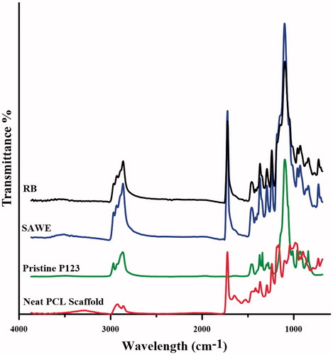
Value γ of SAWE is higher than that of RB; suggesting increased FSEoHP for SAWE and is in agreement with the observations made by TEM images.
Water contact angle and Swelling test
To investigate the surface hydrophilicity or hydrophobicity of neat PCL, SAWE and RB scaffolds, water contact angle measurements were performed. The relation between water contact angle and wicking property depends on surface roughness and chemical composition of the sample. Neat PCL scaffold is hydrophobic with contact angel of approximately 132°. In contrast, for samples containing P123, water contact angle significantly reduces and becomes 0°, indicating that super hydrophilicity conditions reached for blended scaffolds (Supplementary Figure 1). The zero value of SAWE and RB scaffolds water contact angle shows that the contact angle measurements is in fact independent from the methods used to fabricate the scaffolds and solely relies on the P123 presence in the fibers. It should be mentioned that the blending ratio in both samples under study was high and it has been reported elsewhere that PCL blends containing P123 with zero water contact angle can be achieved at ratio’s as low as 5 wt% of Pluronic (Mirhosseini et al. Citation2016). Phase blending of P123 and PCL determines the uniformity of fiber chemical composition. In general, hydrophobic interactions can occur between PCL ethyl and P123 methyl groups thus limiting the integration of P123 PEO blocks into the PCL chains. Due to the presence of water during SAWE electrospinning process, an anchored structure of P123 PPO blocks into the PCL and reassembled brush-like PEO blocks at surface can be postulated. However, according to TEM image (), the zero contact angle value for RB scaffold may be related to the bare P123 accumulations along the fibers which accelerate the wicking process.
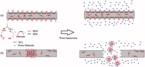
To further investigate the effects of electrospinning method on the final fiber structure, water uptake of the electrospun neat PCL, SAWE and RB scaffolds was evaluated and presented in . As expected, hydrophobic nature of neat PCL scaffold lowers its water uptake ratio to a great extent in comparison with the blended samples. Swelling ratio increases from 50% for neat PCL (at equilibrium condition) to approximately 250 and 270% for RB and SAWE scaffolds (pseudo equilibrium condition), respectively. Presence of P123 in electrospun fibers and the fairly high porosity of the scaffolds are responsible for this 5-fold boost of swelling ratio and rapid swelling behavior. Nevertheless, water uptake percentage remains constant for SAWE in the entire time frame of experiment whereas RB shows a continuous decline after 60 h of water immersion. The latter may happen due to the leach of the phase separated P123 in the length of RB fibers. As mentioned before, RB scaffold comprises of both blended and neat PCL fibers in which only the former enhances scaffold swelling ratio through favorable water-P123 PEO blocks hydrogen bonding. After water immersion, fragmented blended fibers gradually loses their water retention and the as a result the overall swelling ratio of RB decreases. The latency period wherein P123 accumulates inside RB fibers leach into water (60 h) may be related to the thickness of PCL layer surrounding the phase separated area which in turn is a function of primary blend ratio of the electrospinning solution. Therefore, the permanency of water uptake percentage is associated with the integrity of scaffold. schematically represents the RB and SAWE nanofibrous behavior after water immersion. Due to the low FSEoHP value of RB, the phase separated P123 chains accumulate within the fibers. P123 agglomerates would then micellize at a certain time of water immersion which results in fragmented fibers and disintegrated scaffold. In contrary, water exposure during SAWE method positions P123 uniformly on the surface of fibers and prevents the formation of P123 agglomerates. This uniformity in turn results in intact fibers while immersed in water. Endurance of scaffold integrity in aqueous media is crucial for tissue engineering applications.
Figure 7. The swelling ratio of electrospun neat PCL, SAWE and RB scaffolds.
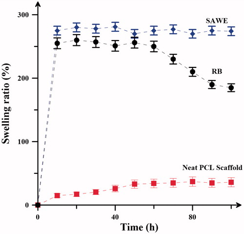
Figure 8. Schematics of (a) SAWE and (b) RB fiber behavior before and after water immersion.
UV-visible spectra
presents the release profiles of DPH from prepared scaffolds in a cumulative fractional manner. Moreover, EquationEquations (3)(3) , Equation(4)
(4) and Equation(5)
(5) were fitted to release profiles and the related parameters were tabulated in . As seen in , the final amount of DPH released from SAWED is 40% lower than that of RBD; plus, in the entire time frame of study, SAWED release pattern does not cross that of RBD. Protonation of DPH through proton transfer between DPH amine groups and water molecules from humidity grants the drug molecules with a tendency to be placed on the surface of charged jet during the electrospinning process. Therefore, both SAWED and RBD release profiles suffer from the initial burst wherein considerable amount of DPH, placed on the surface of electrospun fibers, is being released in a very short period of time into the buffer. RBD burst release is more significant in comparison with SAWED and fibers lose nearly 60% of their DPH supply. The burst component of release is followed by a prolonged period of drug release and can be seen for both release curves. Fast solvent evaporation and fiber solidification during electrospinning process entrap drug molecules inside the fibers and consequently form the prolonged component of drug release. However, in the case of RBD, another semi-burst release can be observed after the plateau of prolonged release period which makes the overall pattern an abnormal two-stage phased release profile; considering that each stage of drug release contains both components of burst and prolonged release. The burst release of the second stage happens approximately at the beginning of the third day of in vitro studies (phase 2 of burst release). From ATR-FTIR spectra of drug-loaded scaffolds, it can be concluded that the peak at 1473 cm−1 related to the tertiary amine groups is intensified for both SAWED and RBD spectra due to the presence of DPH in the fiber composition (Supplementary Figure 2). However, no shift in the characteristic peaks of PCL and P123 for drug-loaded samples can be detected (with respect to the ATR-FTIR spectra of SAWE and RB). This observation indicates that the molecular structure of blended polymers remained unchanged after drug incorporation and electrospinning process. Therefore, for a blended composition with no specific molecular interactions or distinct core-shell structure, the occurrence of two-stage drug release for RBD can be related to the P123 accumulations within fibers: after a plateau region for DPH release from RBD fibers (which lasts for about 65 h), a thin layer of PCL at the surface of fibers swells and the phase separated DPH containing pockets of P123 become exposed to water which results in a second burst release. This assumption is in line with the results from scaffold swelling ratio (. There, a steady reduction in RB swelling ratio was observed after 60 h of water immersion. Moreover, SEM images of RB scaffold after being submerged in water revealed fiber fragmentation and scaffold disintegration. Similar pulsatile release profile has been reported by Kaassis and coworkers for PEO-sodium alginate (SA) drug (sodium ibuprofen, SI) loaded nanofibers at a certain pH. In their study, fast or burst release of SI from PEO chains which are highly water soluble was followed by a plateau; comprising the first stage of release. The low solubility of SA at pH 3 delayed the release of entrapped SI. However, a second burst release happened eventually as a result of fiber (mainly composed of SA) swelling, hence a two-stage release profile was obtained (Kaassis et al. Citation2014). In contrast, the common one-stage release profile of SAWED suggests less phase separation and a high FSEoHP value. All three models used for describing the release mechanism of SAWED and RBD have acceptable coefficient of determination (higher than 0.99%), indicating the applicability of these models. Among these models, Weibull equation finely fits the release profiles and less divergently predicts the first 60% of drug release. Compared to SAWED, the value of the parameter α for RBD is considerably higher. SEM image of RB after water immersion showed the fragmented blended fibers while neat PCL fibers remained intact. This kind of fiber elimination results in higher specific area and probably happens in an adventitious manner during RBD release study which explains the high value of the parameter α of Weibull equation. Forsgren et al. (Citation2010) investigated the drug release from crushed and uncrushed pellets and stated that values of β exponent of Weibull equation lower than 0.35 correspond to diffusion transport in a disordered system. Due to the non-woven fibrous structure of scaffolds under study, β exponent is approximately equal to or lower than 0.35 for both drug-loaded samples (Morie et al. Citation2016). However, mentioned exponent is slightly higher for SAWED. During SAWE electrospinning, P123 chains migrate toward the surface of the evolving charged jet as evidenced by the TEM image presented in . This reassembly changes the diffusion paths of the DPH molecules trapped inside the fibers and as a result the value of β exponent increases. Peppas and Modified Korsmeyer–Peppas models can also ably describe the first stage of SAWED and RBD drug release. The n value for both drug-loaded samples is below 0.45 which shows the approach of drug release mechanism toward Fickian diffusion controlled release. The occurrence of a negative b in modified Korsmeyer–Peppas model has been considered as an anomaly and usually happens when the drug carrier is placed in a dialysis bag (Tan et al. Citation2014). Although the release setup in this study did not contain a dialysis bag, the value of the component b for SAWED release fit is also negative and may be related to the presence of P123 layer at the surface of the fibers. Acting as a dialysis bag, this layer limits the fast diffusion of DPH molecules trapped inside the fibers and hinders the burst release.
Figure 9. Fractional cumulative release of DPH from SAWED and RBD together with Peppas, Weibull and Modified Korsmeyer–Peppas models fits.
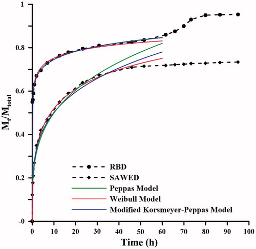
Table 2. Parameters of fitted models on drug release profiles.
Conclusion
Fiber surface enrichment of hydrophilic polymer through blend electrospinning determines the division of hydrophilic polymer total weight percentage into the bulk and surface of electrospun fibers. A motive factor during RB electrospinning which can compel the hydrophilic polymer to remain at the surface of developing electrospun jet may increase the FSEoHP drastically. In our proposed SAWE electrospinning method, DI water, a non-solvent for PCL and immiscible with chloroform, was selected as this motive to direct the P123 chains toward the surface of the forming jet when they are still in solution and have the time to migrate and reassemble. The effectiveness of this method was established in this article. The selected PCL-P123 mole ratio in this study was intended to fully demonstrate the extent of phase separation in RB scaffold and the applicability of the SAWE method. SEM images of the scaffold produced by the modified method revealed smooth fibers with no evidence of water drops. Moreover, TEM images confirmed that considerable amounts of reassembled P123 with a linty appearance reside at the surface of the fibers prepared by this method. No significant change in the molecular structure toke place upon blending for both methods. Due to the presence of P123 in the electrospinning solution, water contact angle of RB and SAWE dramatically decreased to 0° from 132° of neat hydrophobic PCL scaffold; suggesting that super hydrophilicity can be reached regardless of the electrospinning method. However, water swelling ratio of the scaffold produced by RB method decreases gradually after 60 h of water immersion due to the mat disintegration while that of SAWE remained constant in the entire time frame of study. An unusual two-stage drug release for RBD suggested that the fragmentation of drug-loaded fibers can occur within the first three days of scaffold water immersion, an indication of P123 phase separation and low FSEoHP value. According to the results, it can be concluded that SAWE electrospinning of hydrophobic polymers: can be carried out with adding high percentages of Pluronic as surfactant to the electrospinning solution, has the ability of tuning the arrangement of polymeric chains, promotes the water swelling ratio without jeopardizing the integrity of the resulted scaffold and finally can act as a proper drug carrier.
Funding information
This study was not funded by any organization.
Disclosure statement
The authors declare that they have no conflict of interest. The authors alone are responsible for the content and writing of the paper.
References
- Ahmadi-Aghkand F, Gholizadeh-Ghaleh Aziz S, Panahi Y, Daraee H, Gorjikhah F, Gholizadeh-Ghaleh Aziz S, Hsanzadeh A, Akbarzadeh A. 2015. Recent prospective of nanofiber scaffolds fabrication approaches for skin regeneration. Artif Cells Nanomed Biotechnol. [Epub ahead of print]. doi: 10.3109/21691401.2015.1111232.
- Akkas T, Citak C, Sirkecioglu A, Güner FS. 2013. Which is more effective for protein adsorption: surface roughness, surface wettability or swelling? Case study of polyurethane films prepared from castor oil and poly (ethylene glycol). Polymer Int. 62:1202–1209.
- Arcana IM, Bundjali B, Hasan M, Hariyawati K, Mariani H, Anggraini SD, Ardana A. 2010. Study on properties of poly (urethane-ester) synthesized from prepolymers of ɛ-caprolactone and 2, 2-dimethyl-1, 3-propanediol monomers and their biodegradability. J Polymer Environ. 18:188–195.
- Arima Y, Iwata H. 2007. Effect of wettability and surface functional groups on protein adsorption and cell adhesion using well-defined mixed self-assembled monolayers. Biomaterials. 28:3074–3082.
- Cui W, Li X, Zhu X, Yu G, Zhou S, Weng J. 2006. Investigation of drug release and matrix degradation of electrospun poly(DL-lactide) fibers with paracetanol inoculation. Biomacromolecules. 7:1623–1629.
- Dash TK, Konkimalla VB. 2012. Poly-є-caprolactone based formulations for drug delivery and tissue engineering: a review. J Control Release. 158:15–33.
- de Valence S, Tille J-C, Chaabane C, Gurny R, Bochaton-Piallat M-L, Walpoth BH, Möller M. 2013. Plasma treatment for improving cell biocompatibility of a biodegradable polymer scaffold for vascular graft applications. Eur J Pharmaceut Biopharmaceut. 85:78–86.
- Emami SH, Pirbasti ZH, Hasani‐Sadrabadi MM, Kordestani SS. 2011. The effect of isopropanol addition on enhancement of transdermal controlled release of ibuprofen from ethylene vinyl acetate copolymer membranes. J Appl Polymer Sci. 122:3048–3054.
- Forsgren J, Jämstorp E, Bredenberg S, Engqvist H, Strømme M. 2010. A ceramic drug delivery vehicle for oral administration of highly potent opioids. J Pharmaceut Sci. 99:219–226.
- Fukamachi T, Endo T, Yabuki Y, Ogura T, Misono T, Torigoe K, et al. 2015. Synthesis of silica nanotube using myelin figure as template and their formation mechanism. J Oleo Sci. 64:663–672.
- Gharaei R, Tronci G, Davies RP, Goswami P, Russell SJ. 2016. An investigation into the nano-/micro-architecture of electrospun poly (ε-caprolactone) and self-assembling peptide fibers. MRS Adv. 1:711-716.
- Hu J, Prabhakaran MP, Ding X, Ramakrishna S. 2015. Emulsion electrospinning of polycaprolactone: influence of surfactant type towards the scaffold properties. J Biomater Sci Polymer Ed. 26:57–75.
- Hunt JA, Chen R, van Veen T, Bryan N. 2014. Hydrogels for tissue engineering and regenerative medicine. J Mater Chem B. 2:5319–5338.
- Kaassis AY, Young N, Sano N, Merchant HA, Yu D-G, Chatterton NP, Williams GR. 2014. Pulsatile drug release from electrospun poly (ethylene oxide)–sodium alginate blend nanofibres. J Mater Chem B. 2:1400–1407.
- Kim H, Fassihi R. 1997. Application of a binary polymer system in drug release rate modulation. 1. Characterization of release mechanism. J Pharmaceut Sci. 86:316–322.
- Kim G-M, Le KHT, Giannitelli SM, Lee YJ, Rainer A, Trombetta M. 2013. Electrospinning of PCL/PVP blends for tissue engineering scaffolds. J Mater Sci Mater Med. 24:1425–1442.
- Kurusu RS, Demarquette NR. 2015. Blending and morphology control to turn hydrophobic SEBS electrospun mats superhydrophilic. Langmuir. 31:5495–5503.
- Mirhosseini MM, Haddadi-Asl V, Zargarian SS. 2016. Fabrication and characterization of hydrophilic poly(ɛ-caprolactone)/pluronic P123 electrospun fibers. J Appl Polymer Sci. 133. doi: 10.1002/app.43345.
- Morie A, Garg T, Goyal AK, Rath G. 2016. Nanofibers as novel drug carrier – an overview. Artif Cells Nanomed Biotechnol. 44:135–143.
- Neppalli R, Marega C, Marigo A, Bajgai MP, Kim HY, Causin V. 2010. Poly(ɛ-caprolactone) filled with electrospun nylon fibres: a model for a facile composite fabrication. Eur Polymer J. 46:968–976.
- Oh SH, Lee JH. 2013. Hydrophilization of synthetic biodegradable polymer scaffolds for improved cell/tissue compatibility. Biomed Mater. 8:014101.
- Papadopoulou V, Kosmidis K, Vlachou M, Macheras P. 2006. On the use of the Weibull function for the discernment of drug release mechanisms. Int J Pharmaceut. 309:44–50.
- Peppas N. 1985. Analysis of Fickian and non-Fickian drug release from polymers. Pharm Acta Helv. 60:110.
- Schmidt JJ, Gardella JA Jr, Salvati L Jr. 1989. Surface studies of polymer blends. 2. An ESCA and IR study of poly (methyl methacrylate)/poly (vinyl chloride) homopolymer blends. Macromolecules. 22:4489–4495.
- Seth A, Katti DS. 2012. A one-step electrospray-based technique for modulating morphology and surface properties of poly (lactide-co-glycolide) microparticles using Pluronics. Int J Nanomed. 7:5129–5136.
- Shi Q, Ye S, Kristalyn C, Su Y, Jiang Z, Chen Z. 2008. Probing molecular-level surface structures of polyethersulfone/Pluronic F127 blends using sum-frequency generation vibrational spectroscopy. Langmuir. 24:7939–7946.
- Song W, Mano JF. 2013. Interactions between cells or proteins and surfaces exhibiting extreme wettabilities. Soft Matter. 9:2985–2999.
- Sun H, Wirsén A, Albertsson A-C. 2004. Electron beam-induced graft polymerization of acrylic acid and immobilization of arginine-glycine-aspartic acid-containing peptide onto nanopatterned polycaprolactone. Biomacromolecules. 5:2275–2280.
- Tan D, Yuan P, Annabi-Bergaya F, Liu D, Wang L, Liu H, He H. 2014. Loading and in vitro release of ibuprofen in tubular halloysite. Appl Clay Sci. 96:50–55.
- Valizadeh A, Bakhtiary M, Akbarzadeh A, Salehi R, Frakhani SM, Ebrahimi O, Rahmati-yamchi M, Davaran S. 2016 Preparation and characterization of novel electrospun poly (ε-caprolactone)-based nanofibrous scaffolds. Artif Cells Nanomed Biotechnol. 44:504–509.
- Van der Schueren L, De Schoenmaker B, Kalaoglu ÖI, De Clerck K. 2011. An alternative solvent system for the steady state electrospinning of polycaprolactone. Eur Polymer J. 47:1256–1263.
- Vasita R, Mani G, Agrawal CM, Katti DS. 2010. Surface hydrophilization of electrospun PLGA micro-/nano-fibers by blending with Pluronic F-108. Polymer. 51:3706–3714.
- Venugopal J, Zhang Y, Ramakrishna S. 2005. Fabrication of modified and functionalized polycaprolactone nanofibre scaffolds for vascular tissue engineering. Nanotechnology. 16:2138.
- Wu S, Wu J, Yue J, To MK, Pan H, Lu WW, Zhao X. 2015. Poly (d, l-lactic acid) electrospun fibers with tunable surface nanotopography for modulating drug release profiles. Mater Lett. 161:716–719.