
 ?Mathematical formulae have been encoded as MathML and are displayed in this HTML version using MathJax in order to improve their display. Uncheck the box to turn MathJax off. This feature requires Javascript. Click on a formula to zoom.
Abstract
To create a freehand three-dimensional ultrasound system for image-guided intervention, ultrasound probe calibration process plays an important role. This paper introduces a novel method, based on arbitrary wire phantom, to achieve both spatial and temporal calibration for ultrasound probe. Spatial calibration is realized by solving an optimization problem established by the wires and corresponding intersections in ultrasound plane. Next, temporal calibration is achieved by processing ultrasound image sequence and the corresponding position of optical localizer mounted to ultrasound probe. In order to make up for the deficiency of geometry structure in arbitrary phantom, we develop a point-recognition algorithm to determine the correspondence between wires in phantom space and intersections in ultrasound image space. Extensive comparative experiment is conducted on N-wire phantom and our phantom in 20 independent trials to fully evaluate precision, accuracy, and robustness of proposed calibration method. Shallow probe experimental result shows that proposed method improves average calibration precision to 0.896 mm and accuracy to 1.022 mm, compared to 0.938 and 1.140 mm using N-wire, respectively. Further, we also perform extra independent trials to evaluate the impact of deep image for the proposed method. Result shows the precision ranges from 0.740 to 1.178 mm, and the accuracy ranges from 0.939 to 1.400 mm, which indicates proposed method is potential for probe calibration in ultrasound image-guided intervention.
PUBLIC INTEREST STATEMENT
“Comparing with classical surgical interventions, image-guided minimally invasive alternatives are beneficial for patients and health care system as it is potential for minimizing surgical trauma, saving hospital stay, and reducing complication rates. Recently, ultrasound is popular in surgical interventions because of the characteristics of portability, low cost, real time, and no ionizing radiation. Therefore, ultrasound-guided minimally invasive system is promising to replace classical surgical interventions. Meanwhile, ultrasound probe calibration is essential to align ultrasound image and medical instruments coordinate systems, this part can improve the precision and robustness of such a minimally invasive system effectively. In this work, we develop a novel probe calibration method without depending on any special geometry phantom. Proposed method can reduce production cost of calibration phantom, improve precision and accuracy. Experiments show our method achieves better results with precision increasing 4.5% and accuracy increasing 10.4% comparing with the-state-of-the-art method.”
Disclosure of interest
The authors report no conflict of interest.
1. Introduction
Freehand tracked ultrasound imaging is widely used in several guided interventions, such as biopsy, ablation, and computer-aided surgery (Solberg et al., Citation2009; Xu et al., Citation2008), due to the characteristics of low cost, safe, high temporal resolution, and portable. Tracking is easily achieved by mounting a localizer to probe, and then the probe can be tracked by position sensing system (e.g. optical or electromagnetic tracking device). However, it is not adequate to determine the position of acquired two-dimensional ultrasound images if we just obtain the position of ultrasound probe. Probe calibration is the task of determining the transformation between probe localizer space and ultrasound image space. Therefore, the transformation, which consists of translation and rotation, is a fundamental and noticeable step in ultrasound image-guided intervention.
Methods for ultrasound probe calibration have been widely investigated (Mercier, Langø, Lindseth, & Collins, Citation2005) to facilitate calibration procedure. Only a few research groups (Khamene & Sauer, Citation2005; Muratore & Galloway, Citation2001) complete probe calibration without calibration phantoms, whereas most researchers design different phantoms with known geometry constrains to provide fiducials for probe calibration.
Point phantom is one of the first options to be adopted for probe calibration. It can be formed by a spherical bead-like object (Leotta, Detmer, & Martin, Citation1997) or a pair of cross wire phantom (Detmer et al., Citation1994). While point phantom is easily designed, images acquired by scanning point phantom need to be segmented manually, which makes calibration process time-consuming and tiresome. Hsu et al. (Treece, Prager, Houghton, Houghton, & Gee, Citation2008) proposed an automatic point segmentation algorithm, but recognition of isolated points in ultrasound images is seldom reliable. Plane phantom, typically such as Cambridge phantom (Prager, Rohling, Gee, & Berman, Citation1998) and its variants (Ali & Logeswaran, Citation2007, Varandas, Baptista, Santos, Martins, & Dias, Citation2004), can also achieve probe calibration. It speeds up calibration procedure by developing an automatic point segmentation algorithm. However, scanning from a wide range of angles and positions limits further development in clinical usage. Otherwise, plane reflects much ultrasound energy away, which makes automatic segmentation in some position become relative difficult. N-wire phantom successfully achieves automatic segmentation and rapid calibration. Compared with at least 550 images to calculate acceptable accuracy using point or plane phantom, N-wire phantom just needs 6–30 images (Bouchet et al., Citation2001; Chen, Abolmaesumi, Pichora, & Ellis, Citation2005, Chen, Thurston, Ellis, & Abolmaesumi, Citation2009). Only middle line is considered to compute calibration transform in N-wire phantom; however, higher precision can be achieved if all lines are used. Besides due to the thickness of ultrasound beam, the localization accuracy in ultrasound imaging is usually highly anisotropic. To alleviate the impact from the thickness of ultrasound beam, Carbajal, Lasso, Gómez, & Fichtinger (Citation2013) propose a special cost function which starts from a seed computed with a closed-form solution based on the middle wires and achieves more advanced results.
Inspired by Carbajal et al. (Citation2013), we propose a new method that considers all the wires to perform probe calibration and achieves better results. The difference between Carbajal et al. (Citation2013) and ours is that we directly compute calibration parameters based on the collinearity of wires in phantom and their corresponding intersections in ultrasound plane, instead of doing iteration from a seed solution. Meanwhile, because of the lack of known geometry constrains (e.g. N-wire phantom) in proposed arbitrary wire phantom, we develop a point-recognition algorithm to determine the correspondence between intersections in ultrasound image space and wires in phantom space.
The remainder of this paper is organized as follows. First, an overview of probe calibration process is given. Then, the specification of arbitrary wire phantom is present. Further, we introduce our experimental settings when acquiring ultrasound image sequence and collect localizer tracking information, as well as propose a robust and fully automatic point-recognition algorithm. Subsequently, we achieve both temporal and spatial calibration with fully evaluating precision and accuracy of the proposed method. Finally, extensive comparative experiment with N-wire method and probe calibration with different deep images are conducted, followed by our detailed discussion.
2. Methods and materials
2.1. Probe calibration overview
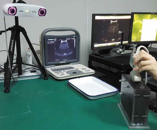
This section presents an overview about probe calibration process (see Figure ), transform matrix involved, and a description about hardware. Images are generated by ultrasound machine (A6 B/W HCU, Sonoscape, China) with a convex probe (C354, Sonoscape, China), then fed to frame grabber (DIV2USB3.0, Epiphan, Canada) and transmitted to central processor (Precision M6800, Dell, China). Simultaneously, optical tracking device (Vicra, Northern Digital Inc., Canada) continuously monitors the localizers attached to probe and phantom, respectively, and then provides position and orientation of probe-localizer and phantom-localizer in tracker device coordinate system (Tracker coordinate frame, abbreviated as T). So spatial accuracy of three-dimensional (3D) tracked ultrasound mainly depends on calibration process, which determines the points in ultrasound plane (Ultrasound image coordinate frame, abbreviated as I) with respect to the probe-localizer (Probe coordinate frame, abbreviated as P).
Figure 1. Transformations involved in calibration process. (a) Arbitrary wire intersection points visible in ultrasound images, (b) ultrasound probe with attached localizer, (c) sensor of optical tracking device, and (d) calibration phantom with attached localizer
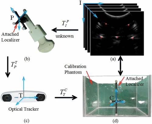
It is noteworthy that ultrasound images are not acquired synchronously with the corresponding tracking recordings, due to which the frame grabber acquisition rate is usually slower than tracking frequency (Shahin, Beširević, Kleemann, & Schlaefer, Citation2014). So, it is essential to develop temporal calibration before studying spatial calibration.
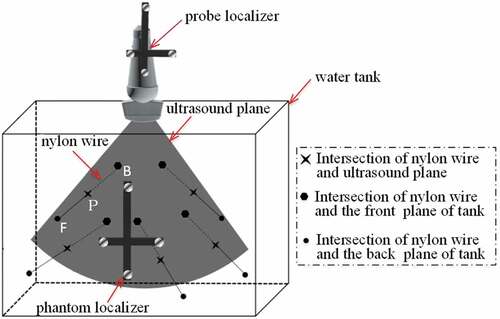
Figure illustrates the design specification of proposed arbitrary wire phantom. To prevent the occurrence of reverberance artifacts (Chen et al., Citation2009), we ensure all five wires are not parallel to each other.
Figure 2. Design specification of our arbitrary phantom. The water tank is 224 mm × 300 mm × 300 mm. There are five holes on both the front and back plate, respectively, to mount nylon wires. Here, we adopt a special geometrical structure that all wires are not parallel to each other
2.2. Arbitrary wire method
For brevity, let and
denote a 3D position in a coordinate frame of A and B, respectively. Furthermore, the 3D position in A coordinate frame can be denoted as
. Then,
represents a homogeneous transform (Sciavicco & Siciliano, Citation2000) that maps from
to
, which can be written as:
The probe calibration process shown in Figure , therefore, can be written as:
where is the intersections of wires and ultrasound plane in ultrasound image space, and we can collect points
by point-recognition algorithm when scan proposed arbitrary phantom. Similarly,
is the intersections of wires and ultrasound plane in calibration phantom space, which locates in the line equations of wires. Moreover,
can be obtained using position tracking device by localizers attached to probe and phantom, respectively.
Here, we suppose that elevation thickness of ultrasound beam is zero. The intersections of wires and ultrasound plane, further, can be written as , where u and v are the pixel index of row and column, respectively, in ultrasound image. So, the probe calibration matrix,
, can be written as:
represents transposed matrix of
. The procedure of ultrasound probe calibration is just the process to find
based on (3). Then, the intersections
in probe coordinate system can be written as:
where T(u,v) is,
In Figure , the equations of nylon wire FB can be written as:
where is the coefficient matrix of the line equation, which can be determined once the wire position of proposed arbitrary phantom is designed by precision machining. Therefore, based on (2)–(3), (5), the following equation makes sense.
In fact, the errors are unavoidable because of the tolerances of machining and point-recognition algorithm. Subsequently, (6) is modified as:
where presents the errors mentioned above. Then, the calibration parameters,
, can be determined by the optimization process as follows:
where is the intersections between the j-th wire with the i-th ultrasound image.
is the corresponding equations of j-th wire.
is the calibration error, so we can determine the calibration parameters
by minimum
.
2.3. Points recognition algorithm
Point recognition in acquired ultrasound images is a key process for proposed calibration method. Because of lacking assistance of a special geometric constrains (e.g. N-wire (Chen et al., Citation2009)), it is difficult to determine which line equation that intersection points belong to. In this section, we propose an effective point-recognition algorithm, which combines point detection and speckle tracking (Harris et al., Citation2010), to address the issue and determine the corresponding between intersections in US image space and line equations in calibration phantom space.
Because point detection is just used once in probe calibration process, it relieves the misgiving that detecting isolate points in ultrasound images is seldom reliable. Firstly, we employ Ostu (Feng, Wang, & Sun, Citation2008) algorithm to remove abundant low echo signal, and then employ morphological operation to clear isolate pixel in US image (see Figure )). Besides, the echo signal from the side face of tank and near crystals would yield adverse effect on point recognition due to high intensity close to intersections. In our experiments, both of them include more pixels (see Figure )). So, we label all connected domains and count the number of pixels, then remove the larger areas (larger than 500 pixels in our algorithm). Once eliminating these negative factors, detecting points is easily realized by using the large difference of echo signal produced by wire and water, respectively (Figure )).
Figure 3. Points recognition algorithm. (a) Original US image, (b) results of threshold segment and morphological operation, (c) label connected domain and removing large areas whose pixel sum are bigger than 500, (d) results of gray threshold segment, (e) the detection result of intersection points, and (f) result of speckle tracking
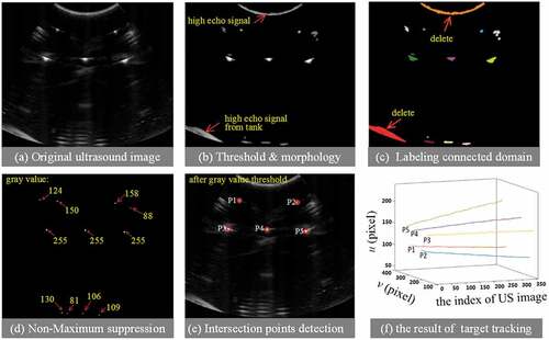
Further, as a stable feature in ultrasound image, speckle has been wildly used to respiratory motion estimation (Harris et al., Citation2010) and echocardiography (Blessberger & Binder, Citation2010). Here, we employ speckle feature and best match (Shepard & Bednarz, Citation2016) to track the positions of intersection points when acquiring consecutive ultrasound images. The initial positions of five intersection points for tracking are determined by the output of point detection part (Figure3()). We set the search window to 40 pixel×40 pixel in all experiments. Figure ) shows tracking results in 350 consecutive ultrasound images.
2.4. Temporal and spatial calibration
Before developing temporal and spatial calibration, we should carefully discuss the issue of speed of sound in water. The speed of sound in water is 1480 m/s at room temperature, which is different from an average velocity of sound 1540 m/s in human body (Boctor, Jain, & Choti et al., Citation2003). Therefore, we heat the water to 37°C, where the speed in it is nearly 1570 m/s, so that the speed of sound in the tank would match the hardwire constant of ultrasonic machine closely.
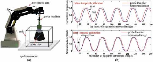
In probe calibration process, ultrasound images and tracking data are from different hardwire devices, so the inherent delay is unavoidable. In order to measure the delay correctly, we design an experimental schedule as Figure ) shows. Meanwhile, ultrasound plane is adjusted carefully so that it is approximately perpendicular to the nylon wire, and then ultrasound probe moves up and down with the traction of mechanical arm (Magician, Dobot, China) periodically. During the motion, both the ultrasound images and the position of probe localizer are recorded simultaneously with the time stamps. In our all experiments, we set that the frequency of frame grabber and optical tracking device are 30 Hz. We then extract intersection points formed by ultrasound planes with nylon wires from acquired ultrasound sequence. Finally, the movement of intersection points from image sequences and position information of probe localizer recorded by tracking system are used to recover the delay. The inherent delay between ultrasound image stream and tracking data stream is near 100 ms as Figure ) shows, which usually cannot be ignored in image-guided intervention.
Figure 4. Temporal calibration. (a) Schematic diagram for temporal calibration. (b) The top is original data extracted from frame grabber and optical tracking device. The bottom is calculating temporal delay between acquired images and the position of probe localizer by maximum correlation
In all, what (8) has established an over-determined system for , and it can be solved using least mean square.
3. Experiments and results
In this section, we first introduce the evaluation methods for precision and accuracy. And then extensive trials are conducted to evaluate the robustness of proposed calibration method, and the response of precision and accuracy in different depth images.
3.1. Evaluation method
In order to evaluate the precision of proposed calibration method objectively, we employ calibration reproducibility (CR) (Carbajal et al., Citation2013) to measure it.
N independent calibration experiments are performed using the proposed phantom, and then we can get a set of N calibration transformations, written as with i = 1,…,N. Eight special points (see Figure ) in ultrasound image are mapped to probe coordinate system using these calibration transformations. If proposed method is precious, each special point should appear the same or roughly the same position in probe coordinate system. So the CR is defined (Carbajal et al., Citation2013) as:
Figure 5. Precision evaluation schedule. (a) The selected points and their positions in ultrasound coordinate system. (b) The selected points are mapped by 20 transformations, respectively
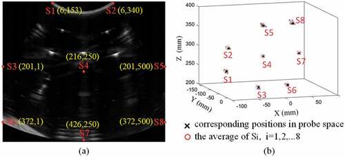
where is the point we select in the ultrasound image. And
is the average position that selected points are mapped by multiple
transformations. Then,
can be written as follows:
According to (9), CR rules out the errors from point-recognition algorithm and tracking device, totally focuses on probe calibration process.
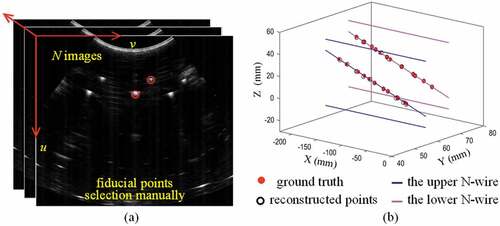
To evaluating calibration accuracy directly is a challengeable task because exact correspondence is not existent between lines in phantom coordinate system and points in ultrasound image coordinate system. So, we employ double-N phantom (Chen et al., Citation2009), which has a definite geometric structure and can provide ground truth points, to evaluate proposed calibration method. Further, we reconstruct the results of double-N positions in the physical phantom space using our calibration matrix and tracking device message. So, accuracy evaluation can be conducted by comparing reconstructed points with ground truth. This process, which also called fiducial registration error (FRE) (Mercier et al., Citation2005), can be expressed mathematically as:
where with i = 1,…,N are N identified positions in double-N phantom and ultrasound image space, respectively. And
are rigid transformations from probe space to tracking space and from tracking space to phantom space, respectively, which can be read from optical tracking device by monitoring localizers directly. Figure shows the error between ground truth and reconstructed points in one calibration trial.
Figure 6. Accuracy evaluation schedule. (a) Selecting fiducial points through scanning double-N phantom manually. (b) Accuracy evaluation between ground truth and reconstructed points. The red filled markers are ground truth which depend on the special geometric structure of double-N phantom. The black unfilled markers are reconstructed points using (2)
3.2. Calibration precision, accuracy, and robustness
The performance of proposed method is impacted by the precision of point-recognition algorithm, optimization method, errors from hardwire devices, etc. Multiple independence trials may be a good idea to vilify the robustness of our method. In this section, we firstly perform 20 independence trials (40 images are acquired by scanning proposed phantom per trial) to calculate our own calibration matrix. Secondly, we employ double N-wire phantom to evaluate the precision and accuracy of calibration process. Here, we also acquire 40 ultrasound images through scanning double-N phantom (Chen et al., Citation2009), and then label the intersections between middle line of N-wire and ultrasound plane manually (see Figure )). Finally, precision, accuracy for the proposed calibration method can be calculated with equations in (9) and (10) .
It needs mentioning that the central frequency of ultrasound probe is 3 MHz, ultrasound focus point is 5.6 cm, and both data acquisition frequency of frame grabber and optical tracking device set to 30 Hz. Besides, we use random number which range is between −0.5 and 0.5 mm to generate .
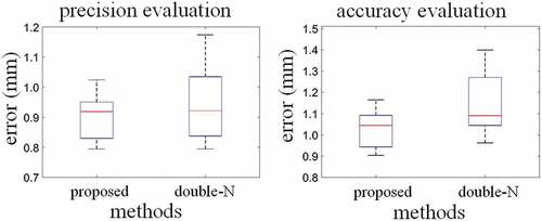
The evaluation results of the proposed method are shown in Figure and Table . Our proposed point- recognition algorithm can identify all intersections and correctly determine corresponding relationship between points in image space and lines in phantom space. The average precision (CR) of 20 independent trials is 0.896 mm with the standard deviation of 0.075 mm and the average accuracy (FRE) is 1.022 mm with the standard deviation of 0.085 mm. Moreover, compared with N-wire, proposed calibration achieves better results with precision increasing 4.5% (from 0.938 to 0.836 mm, see Table ) and accuracy increasing 10.4% (from 1.140 to 1.022 mm, see Table ). Substantial improvement in accuracy evaluation indicates that proposed point-recognition algorithm is more robust than (Chen et al., Citation2009).
Table 1. Error distributions (mm) based on precision and accuracy evaluation for the proposed method and N-wire method
Figure 7. Performance evaluation for proposed and N-wire method. Left is precision evaluation. Right is accuracy evaluation
3.3. Calibration responds for deep imaging
Resolution in single ultrasound image is different from one area to another area. This factor can be decomposed to axial and lateral resolutions. And the axial does not change with the image deep, but the lateral resolution is depth-dependent. Figure ) shows the various appearances in ultrasound image when nylon wire is at different depths. We can see, more far away from ultrasound focused point (UFP), more blurry the appearance is. This phenomenon would influence the accuracy of point-recognition algorithm, further be harmful to proposed calibration method. So, evaluating how image depth influences the precision and accuracy of calibration matrix deserves consideration. Figure ) shows our experimental facility. We simulate various image depths through adjusting the distance between ultrasound probe and uppermost nylon wire. And then, images are acquired while the probe moves horizontally with the traction of mechanical arm.
Figure 8. (a) The shape of intersections determined by the ultrasound axial and lateral resolution. (b) Schematic diagram for exploring how different depth images influences the performance of proposed probe calibration method
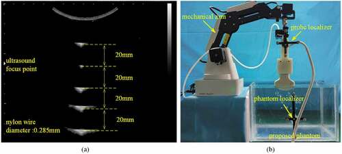
Table shows how five different image depths influence the precision and accuracy of the proposed method. When the distance is 50 mm, we can receive a best calibration matrix. It is because this distance closes to UFP, where the appearance of speckle is close to circle shape. Moreover, the precision, especially accuracy would decrease severely when the image depth is far away from UFP. When the distance is 110 mm, the accuracy is only 1.400 mm. We need to avoid it during ultrasound-guided intervention.
Table 2. Precision and accuracy evaluation for the proposed method with different distances between ultrasound probe and uppermost nylon wire
4. Discussion
In this paper, we propose a potential method for ultrasound probe calibration based on arbitrary wire phantom. This phantom does not depend on special geometric structures (e.g. N-wire phantom). Besides, we develop a novel point-recognition algorithm to determine the correspondence between points in image space and lines in phantom space directly, and it helps us free from precision geometry design. Further, in order to thoroughly evaluate the performance of the proposed method, we perform 20 independence trial to verify robustness and extra five trials to explore the response of precision and accuracy under various image depths. All results verify the effectiveness and robustness of the proposed method. Besides, we also consider the difference of the sound velocity between phantom and human body and develop a reasonable resolution, which simulate the propagation velocity of ultrasound in fresh body through heating water to 37°C.
However, we just consider a special arbitrary wire phantom—all five wires are not parallel to each other. More detailed geometric constrains, such as the spaces among referred nylon wires, worth discussing and exploring. In future, we plan to pay more attention to improve precision and accuracy for deep ultrasound image and more thorough geometrical constrains in arbitrary phantom. We also plan to implement our proposed probe calibration method to clinical ultrasound image-guided biopsy and radio-frequency ablation.
Cover image
Source: Author.
Additional information
Funding
Notes on contributors
Chunxu Shen
Chunxu Shen is with biomedical engineering, Tsinghua University, Haidian District, Beijing, P. R. China, 100084. The correspondence email are [email protected] and [email protected].
Chunxu Shen, graduate student in biomedical engineering, Tsinghua University. His interest is about ultrasound-guided surgery, target tracking and ultrasound physics.
Liushuai Lyu
Liushuai Lyu, graduate student in biomedical engineering, Tsinghua University. His interest is about software development, and image-guided surgery.
Guangzhi Wang
GuangZhi WANG, professor in biomedical engineering, Tsinghua University. His interest is about image-guided surgery, and computer aided diagnosis.
Jian Wu
Jian Wu, associate professor in biomedical engineering, Tsinghua University. His interest is about minimally invasive surgery, and medical robots. Jian Wu received the Ph.D. degree in biomedical engineering from Tsinghua University, Beijing, China, in 2004. Since 2006, he has been with the Institute of Biomedical Engineering, Graduate School at Shenzhen, Tsinghua University, Shenzhen, China, where he has been researching biomedical measurement and computer aided minimally invasive surgery, application of optical measurement in early examination of cancerous tissue.
References
- Ali, A., & Logeswaran, R. (2007). A visual probe localization and calibration system for cost-effective computer-aided 3D ultrasound. Computers in Biology & Medicine, 37(8), 1141–13. doi:10.1016/j.compbiomed.2006.10.003
- Blessberger, H., & Binder, T. (2010). Two dimensional speckle tracking echocardiography: Clinical applications. Heart, 96(24), 2032. doi:10.1136/hrt.2009.173765
- Boctor, E. M., Jain, A., Choti, M. A., et al. (editors). (2003). Rapid calibration method for registration and 3D tracking of ultrasound images using spatial localizer. Medical imaging 2003: Ultrasonic imaging and signal processing; 2003. Munich, German: International Society for Optics and Photonics.
- Bouchet, L., Meeks, S., Goodchild, G., Bova, F. J., Buatti, J. M., & Friedman, W. A. (2001). Calibration of three-dimensional ultrasound images for image-guided radiation therapy. Physics in Medicine & Biology, 46(2), 559–577. doi:10.1088/0031-9155/46/2/321
- Carbajal, G., Lasso, A., Gómez, A., & Fichtinger, G. (2013). Improving N-wire phantom-based freehand ultrasound calibration. International Journal of Computer Assisted Radiology & Surgery, 8(6), 1063–1072. doi:10.1007/s11548-013-0904-9
- Chen, T. K., Abolmaesumi, P., Pichora, D. R., & Ellis, R. E. (2005). A system for ultrasound-guided computer-assisted orthopaedic surgery. Computer Aided Surgery, 10(5–6), 281–292. doi:10.3109/10929080500390017
- Chen, T. K., Thurston, A. D., Ellis, R. E., & Abolmaesumi, P. (2009). A real-time freehand ultrasound calibration system with automatic accuracy feedback and control. Ultrasound in Medicine & Biology, 35(1), 79–93. doi:10.1016/j.ultrasmedbio.2008.07.004
- Detmer, P. R., Bashein, G., Hodges, T., Beach, K. W., Filer, E. P., Burns, D. H., & Strandness, D. E. (1994). 3D ultrasonic image feature localization based on magnetic scanhead tracking: In vitro calibration and validation. Ultrasound in Medicine & Biology, 20(9), 923–936. doi:10.1016/0301-5629(94)90052-3
- Feng, B., Wang, Z., & Sun, J. (2008). Image threshold segmentation with Ostu based on quantum-behaved particle swarm algorithm. Computer Engineering & Design, 29(13), 3429-3434. doi:10.16208/j.issn1000-7024.2008.13.023.
- Harris, E. J., Miller, N. R., Bamber, J. C., Symonds-Tayler, J., Richard, N., & Evans, P. M. (2010). Speckle tracking in a phantom and feature-based tracking in liver in the presence of respiratory motion using 4D ultrasound. Physics in Medicine & Biology, 55(12), 3363–3380. doi:10.1088/0031-9155/55/12/007
- Khamene, A., & Sauer, F. (2005). A novel phantom-less spatial and temporal ultrasound calibration method. Medical Image Computing and Computer-Assisted Intervention : MICCAI International Conference on Medical Image Computing and Computer-Assisted Intervention, 8(Pt 2), 65–72.
- Leotta, D. F., Detmer, P. R., & Martin, R. W. (1997). Performance of a miniature magnetic position sensor for three-dimensional ultrasound imaging. Ultrasound in Medicine & Biology, 23(4), 597–609. doi:10.1016/S0301-5629(97)00043-4
- Mercier, L., Langø, T., Lindseth, F., & Collins, D. L. (2005). A review of calibration techniques for freehand 3-D ultrasound systems. Ultrasound in Medicine & Biology, 31(4), 449. doi:10.1016/j.ultrasmedbio.2004.11.015
- Muratore, D. M., & Galloway, R. L. (2001). Beam calibration without a phantom for creating a 3-D freehand ultrasound system. Ultrasound in Medicine & Biology, 27(11), 1557. doi:10.1016/S0301-5629(01)00469-0
- Prager, R. W., Rohling, R. N., Gee, A. H., & Berman, L. (1998). Rapid calibration for 3-D freehand ultrasound. Ultrasound in Medicine & Biology, 24(6), 855–869. doi:10.1016/S0301-5629(98)00044-1
- Sciavicco, L., & Siciliano, B. (2000). Modelling and control of robot manipulators. London: Springer.
- Shahin, O., Beširević, A., Kleemann, M., & Schlaefer, A. (2014). Ultrasound-based tumor movement compensation during navigated laparoscopic liver interventions. Surgical Endoscopy & Other Interventional Techniques, 28(5), 1734–1741. doi:10.1007/s00464-013-3374-9
- Shepard, A., & Bednarz, B. (2016). SU-G-BRA-02: Development of a learning based block matching algorithm for ultrasound tracking in radiotherapy. Medical Physics, 43(6Part25), 3635.
- Solberg, O. V., Langø, T., Tangen, G. A., Mårvik, R., Ystgaard, B., Rethy, A., & Hernes, T. A. N. (2009). Navigated ultrasound in laparoscopic surgery. Minimally Invasive Therapy, 18(1), 36–53. doi:10.1080/13645700802383975
- Treece, G. M., Prager, R. W., Houghton, N. E., Houghton, N. E., & Gee, A. H. (2008). Comparison of freehand 3-D ultrasound calibration techniques using a stylus. Ultrasound in Medicine & Biology, 34(10), 1610–1621. doi:10.1016/j.ultrasmedbio.2008.02.015
- Varandas, J., Baptista, P., Santos, J., Martins, R., & Dias, J. (2004). VOLUS–A visualization system for 3D ultrasound data. Ultrasonics, 42(1), 689–694. doi:10.1016/j.ultras.2003.11.006
- Xu, S., Kruecker, J., Turkbey, B., Glossop, N., Singh, A. K., Choyke, P., … Wood, B. J. (2008). Real-time MRI-TRUS fusion for guidance of targeted prostate biopsies. Computer Aided Surgery Official Journal of the International Society for Computer Aided Surgery, 13(5), 255. doi:10.3109/10929080802364645