
Abstract
Results of analyses on localized jointing system are presented to study the link of groundwater inflow and joint orientations along the 2000 m excavation of Tunnel Boring Machine (TBM-1) site, Karak in conjunction with the construction of Pahang–Selangor Raw Water Transfer Tunnel project. Geology along the tunnel route is predominantly the Main Range Granite Batholith with a lesser extent of metasedimentary rocks of the Karak Formation. Structurally, TBM-1 is dominated by joints oriented at N–S, NW–SE, and NE–SW directions. Strike slip faults that cross-cut the intrusive Main Range Granite rocks trending faults formed the most prominent structures in the vicinity of the Karak. This section of tunnel alignment consists of 2000 meters in length of Ch.8,821.77 m to Ch.10,821.77 m; 456 joints were mapped to create anisotropic conditions of rock section. Eleven significant locations experienced stoppages, thereby affecting the TBM daily progress, and such stoppages were mainly caused by sudden high-pressure groundwater inrushes or wet joint condition. Potential leakage places are identified by three main types of joints orientations. The most permeable tunnel section is in parallel with the main lineament orientation, followed by perpendicular to the tunnel drive direction, and crossing some voids that create pocket water zones.
PUBLIC INTEREST STATEMENT
The invention of Tunnel Boring Machine (TBM) has revolutionized the demand for more high-profile tunnel constructions; making it bigger, deeper and longer than the previously built. This trend is predicted to continue with the tunneling activity around the world to remain booming with the general growth of construction and the world economy. But, in tunneling project, the bigger the scale of project, the greater the engineering challenges to deals with. This paper presents one of the biggest challenges in any tunnelling project when digging through the unforeseen underground condition, which is the potential of groundwater flooding. High groundwater flows into the tunnel area is one of the most unpredictable events in tunneling due to various factors such as the complex geology and environmental conditions. Nonetheless, this research only deals with the crack or fractures properties found in the bedrock. These cracks behave as a piping system for water to easily move and finally flow into the tunnel area that at present acts as a sink.
1. Introduction
Groundwater inflow into underground excavations is one of the most unpredictable hazards in rock tunneling. It is difficult to accurately identify the location of high permeable zone and thus to estimate the exact amount of inflow into tunnels. Even the highly previous structural features showed no threat to the tunnel at a distance of greater than two tunnel-diameters from the excavation (Moon and Jeong Citation2011). The presence of these highly pervious features connected to a large source of water can have devastating effects resulting in flooding and abandonment of the excavation. Some of these geological features and its related disasters have been frequently reported in tunnels, such as the Long Zagros tunnel (Shahriar, Sharifzadeh, & Khademi, Citation2008) and Alborz tunnel (Wenner & Wannenmacher, Citation2009) in Iran. Several other tunnels were reported in other countries (Tseng, Tsai, & Chang, Citation2001; Song, Cho, & Chang, Citation2012).
The exact estimation of water inflow into tunnels is still a challenge for many due to various factors such as the rock mass permeability and environmental conditions (Palmström Citation2009). Geological structures such as fault and open fractures are predominantly the path for groundwater inflow in low matrix permeability or hard rock formation. Or in some other cases, such as in a construction of tunnel and underground cavern, these features are the only pathway for the groundwater to flow. These features have different behaviors of hydraulic conductivity and it depends on the properties of the features encountered (Zimmerman and Bodvarsson Citation1996). These properties have extensively been studied in predicting water inflow in tunnels (Hamm et al. Citation2007; Zarei et al. Citation2011, Citation2013). According to (Hamm et al., Citation2007), fractures properties, as of aperture, frequency, length, orientation inter-connection, angle, filling materials and features of the fracture plan have strong relation to the hydraulic conductivity to enable better transmissivity of groundwater within the permeable of rock mass. He compared two properties of fracture, namely, frequency and aperture, and discovered that the aperture of fracture has a stronger relationship with permeability than the frequency. Huang et al. (Citation2016) showed that the hydraulic conductivity of groundwater of a coal mine in Shandong Province, Eastern China is strongly related to rock structure, as the values of hydraulic conductivity was approximately 50 and 1500 greater in cataclastic structure than the thinly stratified structure and a stratified structure.
Previous studies mentioned various factors contributing to the measured flow pattern, such as fracture geometric parameters, in-situ stresses and excavation disturbance (Illman Citation2006). Three strongly proven hypotheses on the significance of geological parameters on the estimation of groundwater inflow were discussed, related to the quality of rock mass using Q-system, the behavior of joints towards the major principal stress and contact boundary zone of rock formations (Holmøy and Nilsen Citation2014).
Countless analyses emphasizing analytical, empirical and numerical approaches have been presented in the last decades to predict the groundwater flow into rock tunnels. As to study the groundwater can never be simple, study of hydrogeological factors using analytical and numerical tools has often failed due to generalization and simplification of important parameters, especially at terrain relating to crystalline hard rock such as; as granite or metamorphic rock. Therefore, having a reliable set of data on location, rock samples, and the amount of groundwater inflows is important. Because of complicated geological features, acquiring accurate geological data individually for each geological feature is difficult. Moreover, access to individual data and construction of a model for each geological feature is practically tedious, time-consuming, and expensive for tunnel engineers. Hence, the objective of this research is to evaluate the high groundwater inflow to rock tunnels using the characterization of main geological features with several approaches listed as follows: (1) continuation of discontinuities zone and hydrogeology and (2) the highest rate of water inflows indicate a trend of the joint sets.
2. Data and methods analysis
Completed in 2014, the RM 9 billion Pahang Selangor Raw Water Transfer (PSRWT) project pumps 1,890million liters of raw water daily from Sungai Semantan in Pahang to the Hulu Langat water treatment facility in Selangor. Upon completion, the tunnel will transfer 27.6 m3/sec of water to a new treatment plant that will feed drinking water into the distribution network of Kuala Lumpur city region. The system will supply water to about 7.2 million people for project owner KeTTHA (after Malaysian Ministry of Energy, Green Technology, and Water).
Figure shows the cross-sectional of PSRWT and the location of the site within the study area. Figure shows the 44 km long tunnel route from the basin to the treatment plant and schematic of the proposed PSRWT project and its distribution works, dam, and intakes. Tunnel Boring Machine (TBM)-1 site, which was excavated at Karak, Pahang was selected as the case. In Karak site, TBM-1 is most unexpectedly encountered few locations of high water-bearing zones. One of the locations is at CH8, 143 (TD1322) of approximately 10 tons/min (average of 4.1 ton/min) of sudden inrush warm water was recorded. Another encountered was at CH9, 939 (TD3118) to CH10, 019 (TD3198), where approximately 10.7 ton/min of warm water at temperature 33°C inrush into the tunnel from highly fractured, smooth planar, closely to medium-spaced joints, oriented at N180°/70°—80°. The rock mass conditions were generally good, classified as rock class CII to D, based on Japanese Highway system of rock mass classification.
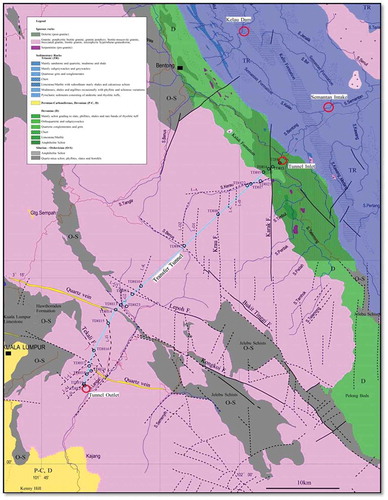
Figure 1. The location map of the study area in conjunction with PSRWT tunnel project with adjacent reservoirs and rivers.
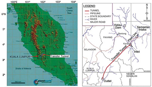
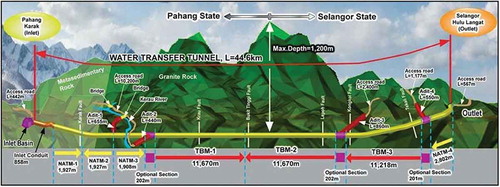
Figure 2. The cross-section of PSRWT tunnel project from Karak to Langat crossing the Titiwangsa Main Range Granite body (After KeTTHA, Citation2000).
In this study, permeable geological features from Ch.8,821.77 m to Ch.10,821.77 m of TBM-1 site were mapped in order to define the relationship between geological features and groundwater inflow. To do this, much details analysis on the effect of structural features studied by the previous researchers were analyzed. At first, based on geological investigations, 11 discrete zones with local inflows of up to 2000 liter/minute were identified along the tunnel, as shown in Figure (a-b), and Figure . Afterward, water inflows were compared with the characteristics of geological features in each area that represents different rock mass properties of granitic body.
Figure 3. Heavy water flow, at right crown and wall of an average rate of 3.5 ton per minute. (Location: TD 3376.6, TBM-1, Karak).
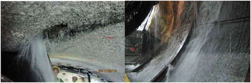
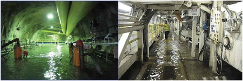
Figure 4. (a) Existing pipeline damaged due to water hammer with installation of additional pump (55 kW x 2, 110 kW x 1) at chamber; (b) Water inflow at TBM back up trailer (Max. 1.3 m high at TBM).
3. Geology of tunnel alignment
The 44.6 km long tunnel of 5.2 m diameter is traversing the Main Range Granite. Intake elevation of the invert is 80.5 m and outlet elevation is 57.6 m. The profile along the tunnel shows maximum overburden of approximately 1246 m at Ch. 24,000 m.
The geology along the PSRWT route of four New Austrian Tunneling Method (NATM)s and three TBMs tunnel is made up predominantly of the Main Range Granite Batholith and to a lesser extent of metasedimentary rocks of the Karak Formation. The Main Range Granite forms the spine of Peninsular Malaysia (Cobbing et al. Citation1992), with general elevation in the vicinity of the project. The highest point of this project is Gunung Nuang at 1493 m; the main rock type is granite, which is formed by several batholitic intrusions (Scrivenor, Citation1931). Granite rock covers about 35 km of the entire 44 km PSRWT tunnel. The formation of the Malayan geosyncline took place in at least two phases: in Lower Paleozoic times and in Upper Paleozoic to Mesozoic times. There appears to be no sedimentation between Lower Devonian and Middle Triassic when deposition of the second geosynclinal phases commenced. Thus, conformity exists between these geosyncline phases. After deposition of the Raub Group, a period of folding and minor igneous activity took place, thereby marking the end of the Mesozoic geosyncline phase (Foo, Citation1983).
The formation of the Malayan geosyncline occurred in at least two phases, namely, in the Lower Paleozoic times and in the Upper Paleozoic to Mesozoic times. No sedimentation was evident between Lower Devonian and Middle Triassic when deposition of the second geosynclinals phases commenced. Thus, conformity exists between these geosyncline phases. After deposition of the Raub Group, a period of folding and minor igneous activity took place, thereby marking the end of the Mesozoic geosyncline phase (Foo, Citation1983). Hutchison (Citation1977) noted that the formation of the Malayan geosyncline was accompanied by emplacement of the Main Range and Manchis Granite masses along with other igneous complexes (Bukit Besar and Bukit Who).
Figure shows the geological map of the study area and project site. The alignment of the tunnel can be clearly seen dissecting about 75% of the length of the Main Range Granite body. TBM-1 is mainly composed of medium to very coarse-grained, porphyritic biotite granite, which is cut by minor porphyritic differentiates and fine-grained variety of granite that represents a later phase of granite intrusion. Some quartz dikes (quartzite) have developed within and parallel to the linear zone of deformation, such as the stretch of lineament lines L–B and L–C, faults, or shear zones. Near such fault zones, proto-mylonite, mylonite, cataclasite, and breccia are produced as a result of shearing within the granite. For some points, aplite is also present in granitic rock mass. Other foundation rocks present within the Main Range Granite are microgranite, monzonite, aplite, granite porphyry, quartz porphyry, felsite, granodiorite, and diorite, and quartz vein. This is recorded by Hutchison (Citation1977; Citation1983) to imply eastern-belt epizonal emplacement resulting in rapid cooling.
Figure 5. The geological map of the study area. (Modified after Maps of Kuala Kubu Baharu (Sheet 86), Selangor (Sheet 94) and Kuala Kelawang (Sheet 95)).
Xenoliths are altered sediments that are presented as dark inclusions in lighter colored granite. Microgranite-pegmatite complexes form composite sub-horizontal sill-like bodies that cut the granite. Other varieties of granite are megacrystic biotite granite, megacrystic muscovite-biotite granite, and equigranular tourmaline-muscovite granite. As mentioned by Cobbing et al. (Citation1992), petrology varies but is generally a medium to coarse-grained porphyritic quartz biotite granite this is of Paleozoic Age (about 200 million years of age) and intrudes rock of the Silurian Age Karak Formation. These metasedimentary rocks, found in the N–E side of the project area, comprise an increasing grade of metamorphism on moving toward the granite contact.
3.1. Structural geology of tunnel alignment
As identified at the regional scale, the tunnel was intersected by several N–S faults along its length. Additional structures, lineaments of NW–SE faults along the western part of the tunnel have been identified from regional topographic trends, such as stream channels and linear features based on aerial photos and satellite images. Faults and lineaments appear to be integral parts of granite emplacement, uplift, and alteration.
Tunnel alignment was intersected by several major structures. The metasedimentary structures of Karak Formation are open-folded, foliated which associated with the jointing system that significantly affects the rock quality. Granite is faulted, in contact with the Karak Formation at the east of study area and strike towards the N–S direction was evident. Several similar N–S trend steeply dipping faults are found along the tunnel extent (Liew, Citation1995). Khalid and Derksen (Citation1971) mentioned a prominent lineament that strikes ENE–WSW, which may be a cross-cutting fault. The faults are generally of the normal type or strike-slip, indicating a general tensional state of stress in the central part of the range.
The topography is matured with deep weathering zones found, which often affects the central part of the range to >100 m depth. The flanks experienced deep incision, exposing less weathered rock, which indicates a prior condition of mature landscape with deep weathering, followed by uplift and possible faulting to form the Main Range; then fluvial erosion by deep incision on the flanks to form the present landscape (KeTTHA, Citation2000).
Three sets of faults have been recognized, more often in igneous rocks than in stratified ones. The oldest is the northerly-trending faults (normal faults) followed by a younger set of NW (wrench fault) strike faults, and N–NE (wrench fault) dip faults (Tjia, Citation1996). Based on site investigation and preliminary studies, igneous rocks are characterized by two sets of prominent, steeply dipping joints and commonly a third set comprising either horizontal or inclined joints. These joints are formed by the relief of tension stresses caused by the contraction of the intrusions during cooling. Jointing in the stratified rocks of the Raub Group has two major directions, NW–SE and NE–SW. The former is parallel to the regional strike and the latter perpendicular to it. They are the results of compressive forces acting in the ENE–WSW direction during regional metamorphism (JKR Report 2000).
A number of faults cut across the proposed transfer tunnel, which lie within the granitic rocks of the Main Range Batholith and intruded into the Paleozoic clastic and calcareous metasediments. The granitic rocks along the proposed transfer tunnel route can be divided into three types, namely, Kuala Lumpur Granite, Genting Sempah Micro granite, and Bukit Tinggi Granite.
A systematic relationship exists between the joints, flow structures, geometry of the granite plutons, dikes, and faults. The orientation of the major joint sets corresponds with the faults and spacing of joints decreases toward the faults. Thus, the joints and faults are cogenetic, meaning that they all formed at about the same time and place. The fieldwork showed both drilling results and field indications of faulting observed in the granitic rocks including zones of brecciation accompanied by slickenside, mortar structure, mylonitization, and in some cases, the presence of quartzite developed within and parallel to the linear zone of deformation.
These quartzites along with other minor rocks differentiate granite porphyry and microgranites were injected during the late stage in the cooling history of the main igneous masses. Near the granite margin, the sedimentary rocks have an average steep dip of 70–75° toward the east, which shallows out to 45–50° further away from the granite. The general strike of the beds is NW to N–NW, parallel to the granite ranges. The rocks suffered both plastic and rupture types of deformation. Plastic deformation resulted in folding and development of flow cleavage within the rock, while rupture deformation resulted in the formation of fracture cleavages, joints, and faults or shear zones (JKR Report 2000).
However, micro-structures such as extensive breccia, cataclastic shearing, mylonites, alteration, bleaching, and late-stage infilling/veining are common in rocks encountered by the drilling. The faults all appear to dip nearly vertical although thickness is unknown. Some of the faults, such as Kongkoi and Tekali, are complex structure with parallel fault-forming zones that could involve deformed and weakened rocks over distances of up to 1.5 km. Numerous faults and lineaments are anticipated along the tunnel with extensive features. Figure shows the lineaments along the 44.6-km tunnel for the project.
Jointing has been assessed from the drill core, during the site investigation, as outcrop is poorly exposed and dominated by weathering processes, as shown in the ductile-sheared granite terrain in the rock core sample (KeTTHA Report of Laboratory Citation2010). Granite is generally displayed as joint pattern that follows the stress history of emplacement, cooling, later uplift, and distressing processes, such as erosion. Granite body commonly has a conjugate pair of steeply dipping joints, with strikes of 60–90° apart and a shallow or near horizontal sent that is a sheet-like joint as a result of de-stressing near the surface.
4. Discontinuities mapping
During the fieldwork, more than 400 joint measurements (consisting of 2000 meter length from Ch.8,821.77 m to Ch.10,821.77 m) and 100 added joint readings were mapped during the construction of the facility. The behavior of joints that influenced the rate of inflows along the tunnel axis is divided into groups of classification to obtain pattern of relationship between the jointing systems (joint orientation) with the water amount. Joints are classified into three domain groups based on their conditions, namely, dry joint, wet joint, and joint with high water inflow. High groundwater inflows are analyzed based on the characteristics of the features and quantity of inflows. Meanwhile, the study area experienced anisotropy and heterogeneous conditions that deal with the main geological structure, which is jointing in particular. Eleven distinguished locations were recorded to experience stoppages (affecting the TBM daily progress), which are mainly caused by sudden high-pressure groundwater inflows or wet joints.
Table shows the details of the extracted 2000 m map inputs, with tabulation of 200 cut-off data sets, which were grouped. The study revealed that the main geological feature of this tunnel, which is the jointing system, is the source of high local inflows and has different effects on the amount of groundwater inflow. All points are arranged in descending trend from TD 2000 m to TD 4000 m. Different color shadings are used to highlight the rate of water inflows.
Table 1. Summary of geological map from TD 2000 m until 4000 m
Note that:
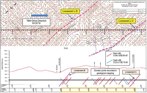
Tunnel direction: N135°W
Main lineament line orientation (L-B and L-C): N180°/70 E
Legend
N180E/70 ~45° from the tunnel drive direction (parallel to lineament line)
N260E/60 ~90° from the tunnel drive direction (perpendicular to lineament line)
Table shows a trend between joint behavior and groundwater inflow based on the following factors:
The highest amount of groundwater inflow was produced by the jointing system, which is parallel to the lineament L–C and L–B ranging N160–180°E/60–85 (Figure ).
Average to lowest amount of water and droplets were produced by the jointing system, which are perpendicular to prominent lineament L–B and L–C and intersecting the tunnel drive with range N250–270°E/70–90.
Wet joints showed the combination of two orientations (in point i and ii).
Figure 6. Non-scale schematic diagram of fault zone with lineament line, location of joints sets and local water inflow through of the study area.
The fundamental law of groundwater inflow through porous media, Darcy’s Law, indicates that groundwater inflow is controlled by a combination of rock permeability and hydraulic gradient within the rock mass. Deformation processes, such as lineament, fault area (between L–B and L–C), and joints are critical to determine the relationship between water inflows in jointed rock mass. However, hydraulic gradients around the fault zones are strongly controlled by hydrogeological processes such as rates of groundwater recharge forcing topography-driven flow; anthropogenic influences such as extraction of groundwater; and deeper processes such as fluid flow driven by sediment compaction (Karasaki, Onishi, & Yu, Citation2008).
Based on the summarized data in Table , the schematic diagram in Figure is produced to determine a closer correlation on the effect of fault zone processes on permeability in the tunnel. Figure shows that TBM-1 is dominated by joints with N–S, NW–SE, and NE–SW directions. Strike-slip faults that cross-cut the intrusive Main Range Granite rocks trending faults formed the most prominent structures in the vicinity of the Karak. In general, the presence of lineaments or faults along the tunnel increases the density of the joints within the rock mass and develops major water pathways as stated by Zarei et al. (Citation2011). Later, areas with high-density faults can act as conduits, barriers, or a combination of conduit-barrier flow systems. Although they are isolated from the fault away from the drainage system and lineaments L–B and L–C, N–S trending strike-slip faults are more pervasively developed in terms of strike extent and width.
By referring to the grouped data, which have been classified based on the geological map and hydrogeological conditions, three main suggestions are derived as follows:
4.1. Inflow through N-S fault zone (±45° from the tunnel direction)
“Water-bearing joints make an angle with nearby major faults of 45°, ±15 (60°), and water-bearing discontinuities are sub-parallel with the largest principal stress,” which is based on Selmer–Olsen’s (Citation1981) theory. A broad zone of distinct and straight but discontinuous lineaments that define the N–S fault zones is a local strike-slip fault. This zone intersects the tunnel at Ch.8800 m (lineament L–B), followed by Sg. Cenui and Ch.10, 800 m (lineament L–C), following a parallel stream. This phenomenon is in agreement with some studies conducted by Berkowitz (Citation2002), Neuman (Citation2005), Balsamo and Storti (Citation2010), and (Holmøy & Nilsen, Citation2014), which state that joint orientations that are aligned to lineaments have enhanced permeability in response to stress and dilatational fractures with no shear displacement (jointed rock) either in or outside of the fault zone.
Inflow through intersections of domain faults orientations and parallel to the lineament line (North–South and East–West)
A fault with +135° from the tunnel direction is a local strike-slip fault, which intersects the tunnel at six locations of approximately NE 270–300°/70–90°. Fracture density gradually increases toward the location of the fault core. These fractures have a conjugate angle with the main fault slip surface. The fault acts as a conduit flow system, producing high groundwater inflow or “wet-joint” conditions.
4.2. Inflow from the pocket water
Between the ground surface and the permanent groundwater level, perched water or trapped local water is expected to be encountered in lenses or pockets. During excavation, TBM might cut some voids or filled with pocket water. A certain amount of water is accumulated or not calculated empirically since it is embedded in the granitic rock; ingress water will flow through the fractures, cracks, or joint path in the granitic body. As time passes, the amount of water will decrease and dry up. Pocket water is becoming a very complicated issue considering that detailed studies have focused on pathway or inflow tracing with dyes or isotopes. Besides, conducting detailed geological and hydrogeological mappings is time-consuming and complicated.
5. Discussion
A total of 456 joints sets were identified from field data, the majority of which trend N–S and dip steeply (shown by the low variance in orientation over changing topography). Bias toward identifying N–S trending lineaments may be due to the influence of topography on the sampling of the image, i.e. most high ridges (where joint orientations are best exposed in North–South and East–West). Therefore, any N–S trending faults/lineaments will be most strongly represented. The relationship between trending of the joint behavior and high water inflow is further analyzed by evaluating engineering geological properties of the rock mass along the tunnel. All the joint sets are analyzed by using stereographical projection and presented as rosette diagram, as shown in Figure . The figure also shows the joint pattern along the study area with dissected lineament. The orientation and dip angle of the three cross joints sets (J1, J2, and J3) increase the possibility for large inflow during operation, as the area is oriented in the northeast/southwest direction with a dip toward the south. The highest joint densities are located at or near the intersection of the three cross-cutting trends of regional lineaments/faults.
Figure 7. Stereographical projection and rosette diagram, an equal area lower hemisphere plot of great circles representing the average dip and dip directions of two discontinuity sets in a rockmass.
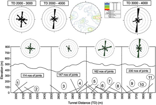
Given that the 2000 meter length of the study area was divided into 500 m each for joint analysis to investigate every 500 m, almost all joints are located at the intersection of two to three major lineaments/faults, with striking N–S. Most of the orientations are aligned in the N–S direction along the prominent N–S lineaments. A weak northeastern trend is also discernable (Figure ). At least three sets of prominent topographic lineaments correspond to permeability-related fault zones. Based on stereographical projection and rosette diagram analysis, the dominant orientations of joints seem to have occurred at the intersection of three cross-cutting trends, as shown in Figure . They are the Kuala Lumpur–Bukit Tinggi trend, N–S trend, and NE–SW trend, which correspond to the NW–SE Bukit Tinggi and Kuala Lumpur Fault Zones, the N–S faults, and the NE–SW faults, respectively.
Jointing system in the study area was affected by lineament L–C introduces permeability, which has a significant effect on processes (such as regional groundwater flow or hydrothermal fluid circulation). These processes may pass through the joints or pathway created by deformations at the fault zone. Hydraulic conductivity depends on the jointing and character of the joint surfaces. Rock mass has high hydraulic conductivity if the joint sets are interlinked with one another, have wide aperture, and are opened or filled with permeable materials. The degree of jointing, spacing between joints, and wideness of aperture in the rock mass depends on the depth. With increasing depth, the joints become tighter with reduced aperture. As a result, hydraulic conductivity of the rock mass decreases with the increasing of depth.
Most of the orientations are aligned along prominent N–S lineaments and are produced to find a closer correlation on the effect of fault zone-hydrogeology relationship processes on permeability into the tunnel. A weak northeastern trend is also discernable. At least three sets of prominent topographic lineaments correspond to permeability-related fault zones.
Based on the stereographical projection and rosette diagram analysis in Figure , the dominant orientations of joints seem to have occurred at the intersection of three cross-cutting trends. They are the Kuala Lumpur–Bukit Tinggi trend, N–S trend, and NE–SW trend, which correspond to the NW–SE Bukit Tinggi and Kuala Lumpur Fault Zones, the N–S faults, and the NE–SW faults, respectively. Jointing system at the study area affected by lineament L-C introduces permeability, which has a significant effect on processes, such as regional groundwater flow or hydrothermal fluid circulation that may pass through the joints or pathway created by deformation at the fault zone.
6. Conclusions
Understanding the methods of discontinuities zone and hydrogeology in this research area is the main objective of this study. The specific effect on joint behavior between lineament–B and lineament–C produces deformations in small or large scale especially at the fault zone. This occurrence introduces heterogeneity and anisotropy in permeability, which has a significant effect on various processes, such as regional groundwater inflow and hydrothermal fluid circulation. Fault zones have the capacity to be hydraulic conduits connecting the underground, but simultaneously, the fault cores of many faults often form effective barriers to groundwater flow. The highest rate of water inflow indicates a trend of the joint sets. Maximum water inflow occurring in parallel with major lineament lines mostly showed the direction of approximately N170–180°/50–70°E, which intersected in the 45° to tunnel driving directions (N135°W).
Acknowledgements
This research project is financially supported by the Ministry of Higher Education, Malaysia under the Exploratory Research Grant Scheme (No. 673044). Permission to assess tunnel sites and data are acknowledged with the support from the Ministry of Energy, Green Technology and Water, Malaysia.
Additional information
Funding
Notes on contributors

Hareyani Zabidi
I am part of Mineral Resources Engineering, Universiti Sains Malaysia (USM). My research is mainly focuses on rock mechanics and engineering geological aspect of mining industries. This scope explores the role of geology in mining and geotechnical to further enhance the engineering quality of everyday practice and thus minimizing the potential of geohazard. My scope of work presents a vital link between the two more conventional fields of geology and engineering, looking particularly at the interaction between discontinuities and deformation consequences to the overall performance of engineering structures and ground projects. Most of the times, my works engage with the government offices, local authorities and related industries, for example studies on the safety practice of rock slope cut in quarries and mines, potential of karst hazard in the Kinta Valley and Klang Valley and the geoengineering aspect of Interstate Raw Water Transfer (ISRWT) project and TNB Hydroelectric project.
References
- Balsamo, F., & Storti, F. (2010). Grain size and permeability evolution and seismic fault zones in high-porosity sediments from the Crotone basin, Southern Apennines, Italy. Marine and Petroleum Geology, 27(4), 1. doi:10.1016/j.marpetgeo.2009.10.016.
- Berkowitz, B. (2002). Characterizing flow and transport in fractured geological media: A re-view. Advances in Water Resources, 25, 861–13. doi:10.1016/S0309-1708(02)00042-8
- Burshtein, L. K. (1969). The problem of conformal transformations of a circle into non-overlapping regions. Matematicheskie Zametki, 6(4), 417–424.
- Cobbing, E. J., Pitfield, E. J., Darbyshire, D. P. F., & Mallick, D. I. J. (1992). The Granites of the South-East Asian Tin Belt. Overseas Memoir 10. London: British Geological Survey, Keyworth.
- Foo, K. Y., 1983. The Paleozoic sedimentary rocks of Peninsular Malaysia – Stratigraphy and correlation. Proceedings of the workshop on stratigraphic correlation of Thailand and Malaysia, 1: Technical papers, Geological Society of Thailand & Geological Society of Malaysia, Thailand, 1–19.
- Goodman, R. E., Moye, D. G., Van Schalkwyk, A., & Javandel, I. (1965). Groundwater inflows during tunnel driving. Engineering Geology, 2(1), 39–56.
- Hamm, S. Y., Kim, M., Cheong, J. Y., Kim, J. Y., Son, M., & Kim, T. W. (2007). Relationship between hydraulic conductivity and fracture properties estimated from packer tests and borehole data in a fractured granite. Engineering Geology, 92(1–2), 73–87. doi:10.1016/j.enggeo.2007.03.010.
- Holmøy, K. H., & Nilsen, B. (2014). Significance of geological parameters for predicting water inflow in hard rock tunnels. Rock Mechanics and Rock Engineering, 47(3), 853–868. doi:10.1007/s00603-013-0384-9.
- Huang, Z., Jiang, Z., Zhu, S., Wu, X., Yang, L., & Guan, Y. (2016). Influence of structure and water pressure on the hydraulic conductivity of the rock mass around underground excavations. Engineering Geology, 202(1), 74–84. doi:10.1016/j.enggeo.2016.01.003
- Hutchison, C. S. (1977). Granite Emplacement and tectonic subdivision of Peninsular Malaysia. Geological Society of Malaysia Bulletin, 9, 187–207.
- Hutchison, C. S. (1983). Multiple Mesozoic Sn-W-Sb Granitoids of Southeast Asia. In J. A. Roddick (Ed.), Circum-Pacific plutonism terranes (Vol. 159, pp. 35–60). Geological Society of Malaysia.
- Illman, W. A. (2006). Strong field evidence of directional permeability scale effect in fractured rock. Journal of Hydrology, 319(1–4), 227–236. doi:10.1016/j.jhydrol.2005.06.032
- Karasaki, K., Onishi, T. W., & Yu, S. (2008). Development of Hydrologic Characterization Technology of Fault Zones, NUMO-LBNL Collaborative Research Project Report.
- KeTTHA (Kementerian Tenaga, Teknologi Hijau dan Air). (2000). Site Investigation Report: Report on Geological Investigation and Construction Material Investigation, Part 1 & Part 2 (Included: Planning and Development of Water Resources for the state of Pahang by SMHB(1992) & SAPROF study for the transfer scheme (OECF, 1999)). Department of Irrigation and Drainage.
- KeTTHA (Kementerian Tenaga, Teknologi Hijau dan Air). (2010). Report of Laboratory of Water Resources for the state of Pahang.
- Khalid, N., & Derksen, S. J., 1971. Geology of the eastern half of sheet 103. Geological Survey of Malaysia Annual Report 81–90.
- Liew, K. K. (1995). Structural patterns within the Tertiary basement of the Strait of Malacca. Geological Society of Malaysia Bulletin, 38, 109–126.
- Moon, J., & Jeong, S. (2011). Effect of highly pervious geological features on ground-water flow into a tunnel. Engineering Geology, 117(3–4), 207–216. doi:10.1016/j.enggeo.2010.10.019
- Neuman, S. P. (2005). Trends, prospects and challenges in quantifying flow and transport through fractured rocks. Hydrogeology Journal, 13(1), 124–147. doi:10.1007/s10040-004-0397-2
- Palmström, A. (2009). Combining the RMR, Q, and RMi classification systems. Tunnelling and Underground Space Technology, 24(4), 491–492. doi:10.1016/j.tust.2008.12.002
- Scrivenor, J. B. (1931). The Geology of Malaya. London: MacMillan.
- Selmer-Olsen, R. (1981). Considerations of large water inflows in deep-seated tunnels. Rock blasting conference (pp. 21.1–21.15). Oslo: Norwegian Tunneling Association.
- Shahriar, K., Sharifzadeh, M., & Khademi, H. J. (2008). Geotechnical risk assessment based approach for rock TBM selection in difficult ground conditions. Tunnel Underground Space Technology, 23, 318–325. doi:10.1016/j.tust.2007.06.012
- Song, K. I., Cho, G. C., & Chang, S. B. (2012). Identification, remediation, and analysis of karst sinkholes in the longest railroad tunnel in South Korea. Engineering Geology, 135(136), 92–95. doi:10.1016/j.enggeo.2012.02.018
- Tjia, H. D. (1996). Tectonic of deformed and undeformed Jurassic-cretaceous strata of Peninsular Malaysia. Geological Society of Malaysia Bulletin, 199, 131–156.
- Tseng, D., Tsai, B., & Chang, L. (2001). A case study on ground treatment for a rock tunnel with high groundwater ingression in Taiwan. Tunnelling and Underground Space Technology, 16(3), 175–183. doi:10.1016/S0886-7798(01)00055-4
- Wenner, D., & Wannenmacher, H., 2009. Alborz service tunnel in Iran: TBM tunnelling in difficult ground conditions and its solutions.1st Regional and 8th Iranian Tunnelling Conference. Tehran, Iran.
- Zarei, H. R., Uromeihy, A., & Sharifzadeh, M., 2009. Prediction of groundwater inflow in to the Semnan tunnel using analytical and empirical methods and comparison with measured value. In: Proceedings, 8th Iranian Tunnelling Conference, Tehran. 308–317.
- Zarei, H. R., Uromeihy, A., & Sharifzadeh, M. (2011). Evaluation of high local groundwater inflow to a rock tunnel by characterization of geological features. Tunnelling and Underground Space Technology, 26, 364–373.
- Zarei, H. R., Uromeihy, A., & Sharifzadeh, M. (2013). A new tunnel inflow classification (TIC) system through sedimentary rock masses. Tunnelling and Underground Space Technology, 34, 1–12. doi:10.1016/j.tust.2012.09.005
- Zimmerman, R., & Bodvarsson, G. (1996). Hydraulic conductivity of rock fractures. Transport in Porous Media, 23(1), 1–30. doi:10.1007/BF00145263.