
 ?Mathematical formulae have been encoded as MathML and are displayed in this HTML version using MathJax in order to improve their display. Uncheck the box to turn MathJax off. This feature requires Javascript. Click on a formula to zoom.
ABSTRACT
Future wireless systems integrating communication and sensing will require handling an enormous amount of data with extremely low latency. Intense video streaming data traffic, pervasive-augmented and virtual reality services, advanced haptic–tactile interaction and holography-type communications, in fact, reveal a trend towards experience-based networks and multi-sense media, which require seamless connectivity and ultra-high capacity. Using current 5G technologies to take mentioned challenges, might not represent the desired solution and a completely new paradigm is needed. Recently, to support this change, scientists have been focusing on the concept of Smart Electromagnetic Environments (SEE), based on deploying a number of smart nodes, whose electromagnetic response needs to be finely adapted to the changing operative conditions. In this framework, a pivotal role is played by reconfigurable intelligent metasurfaces, allowing the implementation of smart skins, reflecting intelligent surfaces, smart repeaters, and intelligent antennas. This paper aims at offering an insightful review of the role of intelligent metasurfaces in advancing the concept of SEE. Different application domains will be illustrated: advanced signal processing at the physical layer, a new generation of smart antennas whose intelligence is enabled by the physical layer, and practical implementation of reflecting intelligent surfaces. With an in-depth analysis of these areas, this review sheds light on how intelligent metasurfaces drive innovation in wireless communication shaping the future of SEEs.
1. Introduction
When switching from 5 G to 6 G wireless systems and comparing the Key Performance Indicators (KPIs) reported in , we immediately recognize that the challenges to face when developing beyond-5 G and 6 G systems are extremely relevant.
Figure 1. Comparison between 5G and 6G wireless systems in terms of key-performance indicators (data source: 5G/PPP whitepaper «Beyond 5G/6G KPIs and target Values», 2022.

For what concerns the peak-data rate, in fact, the expectation is to reach the critical threshold of 1 TB/s while establishing a seamless connectivity characterized by a latency going down to 0.1 ms and a jitter up to 1 μs [Citation1,Citation2]. This would mean that the enormous amount of data required by a cloud of real-time communications, sensing, remote actuation, tactile interaction, data monitoring, data processing, etc. must be processed almost in real time, with further challenges to ensure data security, ultra-high reliability and limit the use of energy towards ever greener and energy sustainable solutions. Another challenging aspect characterizing the next generation of wireless systems is related to the use of mm-waves, which is a direct consequence of the required enormous capacity. However, though mm-waves allow for larger bandwidths, the mm-scale of the wavelength dramatically affects the line of sight (LoS) propagation and increases the sensitivity to the environment, making almost any object a potential obstacle to the propagation of the electromagnetic waves [Citation3–5].
Now, if we want to take the mentioned challenges by using current 5 G technologies, we have a few solutions to choose from. A first one would consist in increasing the effective power radiated by the base station antennas, which results in a more robust LoS link without re-designing the cells. Provided that this solution can be made viable through significant efforts focused on improving the total antenna efficiency by using new low-loss materials and innovative impedance matching strategies, it would not improve the robustness of the no-LoS links and would lead to more critical aspects related to the dramatic increase in the electromagnetic field levels in the environment. The second possible solution, instead, would be based on the deployment of a huge number of access points and base stations, which, on one hand, could alleviate the no-LoS coverage issue but, on the other hand, results in an enormous increase in terms of costs and power consumption, making the system simply unfeasible and economically/environmentally not sustainable [Citation6].
In addition, the extreme densification of access points and base stations would require a massive local computation, implying an enormous amount of power and time to perform the needed signal manipulations, making this solution completely incompatible with the latency and jitter requirements [Citation7]. This last point is the direct consequence of the trend that has been driving wireless communications in the last 50 years based on the extreme virtualization of the hardware functions. Basically, the idea was to pass whatever signal manipulation possible from the physical layer (hardware level) to the higher layers of the pile (i.e. to the digital signal processing modules). This choice requires a set of operations, which take some time to be executed: i. down-conversion from the mm-wave frequencies to the baseband; ii. analog to digital conversion; iii. running algorithms to perform digital signal processing (DSP); iv. digital to analog transformation to re-direct the output signal manipulated by the DSP modules to the radio front-end; v. up-conversion from the baseband to the mm-wave for radiating the manipulated signals in the environment. This scheme is dramatically simplified compared to what happens in reality, where additional operations are needed, anyway, such as beamforming for routing signals in desired directions in space, modulation and demodulation to efficiently code the signals, data extraction (e.g. estimation of the direction of arrival, estimation of the velocity from the Doppler shift, etc.), implementation of proper forwarding strategies, just to name a few. Therefore, these conventional solutions, based on hardware virtualization, lead to a dramatic increase in terms of time and power resources that is not compatible with the latency and jitter requirements for processing the expected enormous amount of data.
The mentioned challenges and the critical aspects related to the use of current 5 G technologies clearly claim for a paradigm change and the use of a new key-enabling technology for the full development of future wireless systems. A candidate technology should be able to handle at the same time the two trends of a. reducing and minimizing hardware virtualization by bringing back to the physical layer some of the functionalities/operations performed at the protocol and algorithm levels and b. making the environment contributing actively to the mm-wave propagation by covering building facades and object surfaces with some devices capable of routing and relying signals in the environment to restore the LoS link.
Both the applied electromagnetics and the wireless communication communities have recognized the third generation of metasurfaces (i.e. Metasurface 3.0), as the required key-enabling technology to successfully address the mentioned challenges (see ) [Citation8–13]. A metasurface working in the mm-wave frequency range is typically a patterned metallic surface printed on an either rigid or flexible dielectric thin layer consisting of a periodic or aperiodic arrangement of unit cells, whose dimension and periodicity are much smaller than the wavelength. Metasurfaces are the 2D counterpart of metamaterials, a novel class of artificial materials developed by many scientific communities since the beginning of this millennium, whose properties allow going beyond what nature and natural materials offer us. When a regular homogenous and periodic metasurface (1st generation) exhibits properties that can be controlled point by point (2nd generation) beaming towards anomalous directions (i.e. anomalous reflection and refraction angles) becomes possible, and, if the properties are controlled not only point by point but also in time, further enhanced functionalities can be enabled, resulting in tunable, reconfigurable, time-modulated, non-reciprocal, cognitive metasurfaces [Citation12].
Figure 2. Historical perspective of the third generations of metasurfaces (from [Citation8]).
![Figure 2. Historical perspective of the third generations of metasurfaces (from [Citation8]).](/cms/asset/18576a08-bb76-4ba4-a361-5f9af7e621dc/tapx_a_2299543_f0002_oc.jpg)
There are several different physical mechanisms that can enable the control of the metasurface properties in time, such as the use of electronic elements or electronic circuits loading the unit cells, the use of liquid crystals, graphene and other tunable/controllable materials, the use of phase-change materials whose phase transition is enabled by temperature, the use of modulated light impinging on photosensitive materials, the use of ferroelectric materials, etc. In the mm-wave frequency range, electronic circuit loading, such as pin diode switches or varactor diodes also combined with other electronic elements, is the most straightforward and typically used technique to enable reconfigurability in time. The different configurations or states are typically controlled by an FPGA.
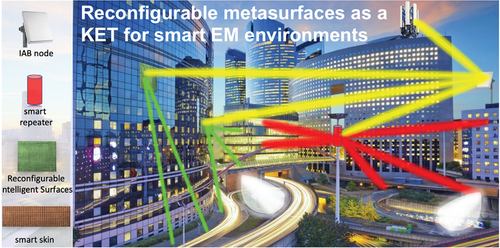
This third generation of metasurfaces, due to the unprecedented and anomalous interaction with the electromagnetic field, enables conceiving and implementing the most convincing solution for deploying future wireless systems based on the concept of Smart Electromagnetic Environments (SEE), also referred to as Smart Radio Environments, sketched in [Citation8–20].
Figure 3. Sketch describing the concept of smart electromagnetic environments. Four different types of smart nodes are deployed in the environment to enhance network coverage.

Here the mm-wave coverage is granted by deploying a number of smart nodes, which can be of either passive (smart skins and reconfigurable intelligent surfaces) or active (smart repeaters and integrated access and backhauling – IAB – nodes) nature [Citation13]. Smart skins are passive metasurfaces characterized by a fixed reflection beam allowing radio coverage in regions characterized by a no-LoS link with the base station [Citation18]. Reconfigurable intelligent surfaces are passive metasurfaces characterized by anomalous routing and relying properties that can be varied in time to track and serve different mobile terminals [Citation21]. Both smart skins and reconfigurable intelligent surfaces do not provide signal boosting, are quite cheap and energy efficient. In fact, they do not amplify the signals and in the smart skin case no power is needed, whilst reconfigurable intelligent surfaces only consume a limited amount of power to control the different states of the metasurface unit cells to generate reflection beams in the desired directions. Smart repeaters, instead, are active nodes working on analog signals as the reconfigurable intelligent surfaces do but enable signal amplification and relying without any form of regeneration [Citation13,Citation22]. Smart repeaters are typically implemented as smart antennas enabling reconfigurable multi-beam generation.
Finally, the IAB nodes are active devices linked to the core network that can decode and forward signals without using any wired connection and allowing not only signal amplification, but also signal regeneration. This characteristic affects the latency of the IAB nodes, which is, however, limited to the coding processes. As such, an IAB node can be thought as a cheaper mini base station characterized by less complexity [Citation13,Citation23].
In this paper, we review the role of the intelligent metasurfaces (Metasurfaces 3.0) in boosting the concept of SEEs, with particular emphasis on three main aspects: 1. metasurface aided signal processing; 2. metasurface aided smart antennas; 3. practical implementation of reflective intelligent surfaces (RIS). In Section II, we present the advantages in terms of reduced complexity, processing speed, and reduced costs, of passing some of the functionalities usually performed at the signal processing level to properly designed intelligent metasurfaces enabling signal processing in an analog way, at the mm-wave frequency, and at the speed of light (no down-conversion to the baseband, analog to digital conversion, and running algorithms are needed). The concept of metasurface aided signal processing is demonstrated through the relevant examples of Doppler shift compensation at the physical layer, low-complexity and low-cost direction of arrival (DoA) estimation, generation of multiple communication channels, multiple false target generation for radar jamming purposes, beamforming metasurfaces. In Section III, we present the new concept of Smart Antennas 2.0, a new generation of smart antennas whose intelligence is not enabled by pairing the antenna with a signal processing module but, rather, by pairing regular antennas with intelligent metasurfaces. In other words, in this case, the intelligence is enabled by the physical layer. Some examples of innovative antennas based on the concept of Smart Antennas 2.0 are presented for both individual radiators and antenna array cases. Finally, in Section IV, we present and discuss some critical implementation aspects of RISs. In particular, we first focus on new strategies based on the vortex mode theory to group the unit cells of the metasurface, resulting in very efficient control mechanisms. Then, we introduce a statistical model aiming at predicting (and eventually restoring) the gain loss due to the phase discretization error and to some non-idealities (e.g. non deterministic effects due to fabrication tolerances, mechanical stress, etc.) characterizing the geometry of a large RIS.
2. Metasurface aided signal processing
In this Section, we discuss the relevance and potential applications of signal processing performed with the aid of intelligent metasurfaces. Signal processing plays a pivotal role in ensuring reliable and efficient wireless communication. It typically involves the manipulation of received signals to extract valuable information, enhance performance, and minimize interference. In conventional systems, this necessitates the involvement of several layers of the protocol stack, spanning from the physical layer to the application layer. This comprehensive approach is employed to execute a wide array of signal processing operations, enabling the extraction of information from the surrounding electromagnetic environment and the implementation of actions that enhance wireless communication performance [Citation24–28]. Key signal processing operations encompass modulation and demodulation, channel estimation, equalization, error detection, error correction, multiple access, and interference cancellation. Furthermore, signal processing is also employed in various other aspects of wireless communication, including beamforming, antenna selection, and power control.
In this context, properly designed intelligent metasurfaces that facilitate signal processing directly at the metasurface level, have the potential to boost a paradigm shift in signal processing within the physical layer. This paradigm shift opens the door to the fastest computational speeds ever achieved, equivalent to the speed of light, all while maintaining a reduced computational cost and complexity. To illustrate the transformative impact of this technology in the context of signal processing and information extraction, we provide a visual comparison in . It compares the operations needed for a conventional wireless access point or relay node to perform a generic operation on an incoming wireless signal with those required by an intelligent metasurface. Notably, the intelligent metasurface does not need to extract data from the wireless signal. Instead, it operates directly on the spatial and temporal properties of the incident electromagnetic wave.
Figure 4. Illustrative block diagrams of (a) a conventional wireless access point/relay node and (b) an intelligent metasurface for signal processing. The signal processing path in a conventional access point/relay node requires much longer time and heavy computational efforts for performing data elaboration and manipulation, whereas metasurfaces can perform it at its surface directly at the electromagnetic wave level.

In the scenario where metasurfaces assist the core network in signal processing operations, whether locally or globally, several advantages over traditional digital-layer approaches become evident:
improved performance: signal processing at the physical layer consistently outperforms digital-layer processing. This is primarily due to the physical layer’s ability to operate at much higher speeds and greater efficiency, unhindered by the constraints of digital circuitry.
reduced latency: signal processing at the physical layer significantly reduces latency in wireless communication systems. It removes the need to capture, process, and retransmit wireless signals, as all operations are performed directly on electromagnetic waves. This eliminates the conversion to the digital domain and back, expediting communication.
reduced power consumption: signal processing at the physical layer leads to reduced power consumption in wireless communication systems. The lower computational demands on devices and networks result in energy savings. Furthermore, the physical layer is not subject to the power constraints imposed by digital circuits.
It is worth mentioning that these intriguing advantages can be even further expanded by means of nonlinear metasurfaces exhibiting bistability, in view of devices equipped with memory capabilities [Citation29,Citation30]. In this way, for instance, the intelligent metasurface could also remember the history of illumination incidence to reflect the signal towards different illumination angles depending on the previous illumination conditions, similarly to what happens to photonic memory devices [Citation31].
To illustrate these advantages within a realistic SEE, this Section presents five pertinent examples of signal processing facilitated by intelligent metasurfaces. First, we present and discuss 1) metasurface-aided Doppler shift compensation at the physical layer and the corresponding metasurface designs that allow self-adapting their properties to achieve higher performances (Section 2.1), then, we present 2) a low-complexity and low-cost direction of arrival (DoA) estimation approach based on modulated metasurfaces (Section 2.2), 3) generation of multiple communication channels at different harmonics whose direction can be controlled at the metasurface level (Section 2.3), 4) the generation of multiple false targets for radar jamming purposes (Section 2.4), and, finally 5) a metasurface that can perform beamforming functionalities at the physical layer (Section 2.5).
These examples collectively demonstrate the transformative potential of intelligent metasurfaces in redefining signal processing within wireless communication systems.
2.1 Doppler shift compensation using (space-)time-modulated metasurfaces
Doppler shift, as established in the literature [Citation32,Citation33], refers to a frequency change of an electromagnetic wave that occurs during the transmission of information between a transmitter and a receiver due to their relative motion in space. In many detection and tracking applications, Doppler shift serves as a crucial parameter for estimating the velocity of a moving target. Various techniques have been developed to accurately measure even the smallest movements [Citation34]. However, in wireless communication settings, the relative motion between transmitter and receiver poses challenges for communication quality: i) in scenarios with high mobility, the relative motion induces a significant frequency shift, leading to the spreading of the signal spectrum components and causing adjacent orthogonal frequency division multiplexed sub-carriers to overlap, leading to an increased inter-symbolic interference; and ii) the fast and continuous motion changes rapidly the electromagnetic environment where the communication is taking place, realizing an effective fading [Citation35]. In such cases, the fading observed at receiver terminals is often attributed to the Doppler shift, simulating an effect similar to multipath propagation [Citation36]. A prominent example is the wireless connectivity in high-speed trains [Citation37–39]. Despite the incorporation of high-mobility requirements into 5 G networks [Citation40], communication quality quickly degrades with increasing relative velocity between transmitter and receiver. Traditional approaches to estimate channel characteristics and compensate for motion-induced fading require complex algorithms performed at the digital layer, incurring substantial computational costs, and introducing latency into the system.
In this context, the concept of Doppler cloak has recently been introduced and extensively explored to render a moving object appear stationary to electromagnetic waves [Citation41-46]. While the original Doppler cloak relied on modulated metamaterials with both spatial and temporal modulation of the permittivity function (as illustrated in ) [Citation47], practical application in real-world scenarios proved challenging due to the large electrical dimensions and the complexity of the modulation scheme required for bulk material properties to effectively compensate for the Doppler effect at the physical layer. Consequently, in [Citation48], an electrically thin reflective metasurface was proposed to induce an artificial Doppler shift by manipulating in time the surface properties (as illustrated in . The operational principle can be summarized as follows: the metasurface properties change over time to exhibit a linearly varying phase of the reflection coefficient (with unitary amplitude). This enables the metasurface to function as a virtually moving metallic panel with an apparent velocity and direction determined by the modulation properties [Citation49,Citation50]. In other words, the incident and reflected fields are interconnected through the reflection coefficient as a function of time, where
represents the frequency shift imposed by the modulation.
Figure 5. Doppler cloak based on (a) space-time modulated metamaterial whose permittivity is function of space and time as and (b) time modulated metasurface whose surface admittance is modulated in time as
.
![Figure 5. Doppler cloak based on (a) space-time modulated metamaterial whose permittivity is function of space and time as εr(t,z)=εr0+δεcos(ωmt±kmz) and (b) time modulated metasurface whose surface admittance is modulated in time as Ys(t)=−jY0tan[0.5ωmt].](/cms/asset/f5606747-f231-4e3b-8883-33254767ef49/tapx_a_2299543_f0005_oc.jpg)
Different approaches have been proposed in the state of the art for implementing the necessary surface time-varying conditions at the metasurface level. The first approach, proposed in [Citation48], is based on reconfigurable high-impedance surfaces (HISs), which can exhibit any phase of the reflection coefficient. In this case, the reflection phase is continuously varied over time in an analog way by using a set of reverse-biased varactors that load the metasurface. The second approach, presented in [Citation51] is still based on HIS, but the phase of the reflection coefficient is now quantized in a discrete number of states that are accessed in sequence during time. Finally, in [Citation52], a space-time varying metasurface based on in-phase and quadrature paths can effectively realize a Doppler cloak when the spatial modulation is turned off to avoid that the excited higher order harmonics are radiated in different directions in space (more about this functionality performed at physical layer will be discussed in Section 2.3).
Compensating Doppler effect represents an important advantage in the SEE framework, as proposed in many recent papers. For example, in [Citation53] a smart metasurface for Doppler shift compensation able to adapt the modulation frequency according to its velocity has been designed and experimentally characterized, showing that a broadband operation can be achieved. In [Citation46], a time modulated metasurface system for achieving angular self-adaptivity has been proposed. In this case, the metasurface can intelligently identify the DoA of the illuminating signal, perform signal processing for Doppler shift compensation, and, finally, reradiate the signal towards the same DoA.
2.2 Low-complexity and low-cost DoA estimation using time-modulated metasurfaces
The estimation of the DoA of electromagnetic waves is a fundamental problem with broad applications in fields like radar, sonar, and wireless communications. It involves the determination of the angle from which a signal arrives at a receiving antenna or an array of antennas. Over the years, various techniques for estimating the DoA have been proposed [Citation54-59], falling into three primary categories: i) beamforming approach, that is based on a regular beamforming network connected to an antenna array, whose parameters are iteratively optimized to identify the direction where the signal comes from; ii) time-delay estimation, which involves measuring the time difference of arrival of the signal at different antenna elements in an array; and, finally, iii) the phase difference estimation, which is based on the phase difference of a signal at different antenna elements in an array at a specific frequency.
These traditional approaches often require complex algorithms executed at the digital layer and necessitate the collection of substantial data through massive phased-array antennas driven by intricate feeding networks, which must be stored in a memory with substantial capacity. While some initial attempts aimed at simplifying the physical equipment by replacing phased-array antennas with rotating antennas or (non-)uniform linear antenna arrays [Citation60,Citation61], metasurface technology has ushered in a further simplification of the hardware requirements [Citation62–68]. However, despite the hardware simplification, these systems still primarily rely on conventional approaches for DoA estimation, resulting in the collection of extensive data, which hinders the shift of signal processing from higher communication layers to the physical layer with minimal computation and latency.
Recently, a new paradigm based on differences in amplitude of scattered waves at a single frequency has emerged [Citation69,Citation70]. Relative amplitude (power) measurements are considerably simpler to obtain, regardless precise positioning or calibration, and demand significantly less memory than time or phase differences captured in real-time by an array of antennas. This paradigm leverages the unique properties of space-time modulated reflecting metasurfaces. Indeed, the system proposed in [Citation70] is extremely simple and comprises only of a space-time modulated metasurface and a single detecting antenna placed in front of it. DoA estimation is achieved by measuring the amplitude imbalance of the reflected fields at the frequencies of the first-order harmonics, i.e., , generated through the interaction between the incident plane wave and the metasurface modulated at the frequency
.
To illustrate the operative principle of this approach, we consider the operative scenario reported in . A space-time modulated metasurface is illuminated by a monochromatic plane wave at frequency propagating with an angle
with respect to the positive z-direction. Regardless the technology used for imparting the space-time modulation on the metasurface, when its surface properties are temporally modulated with frequency
, a frequency mixing between the incident and modulating signals takes place, spreading the energy of the incident field over a number of frequency harmonics located at
, with
. If the metasurface is only temporally modulated, the generated harmonics would always propagate towards the specular direction (
). In this case, despite an unbalancing is always guaranteed by the Manley-Rowe relations [Citation71], if the modulation frequency is much lower than the incident one, i.e.,
, the unbalancing would be negligible and not sufficient to discriminate the two harmonics in amplitude by the detecting antenna. A spatial modulation of the metasurface allows introducing the necessary degree-of-freedom for enhancing the required unbalancing, realizing a radiation pattern asymmetry for the fields scattered at the two first-order harmonics. This allows obtaining a spatial splitting of the radiation patterns, as demonstrated by several works on space-time modulated metastructures [Citation72-74]. In , the field components at the two first-order harmonics
scattered by the metasurface are shown. Since they are propagating towards two separate directions, the detecting antenna placed in the far-field region just above the metasurface can now receive a different amplitude contribution at those frequencies. Since the normalized scattering field pattern of a finite metasurface is analytically defined through the array theory, in [Citation70] the amplitude difference received in the direction of the detecting antenna can be analytically derived and the DoA estimation can be easily performed by reversing such a relationship. In , the comparison between numerical and analytical DoA retrieval function for a metasurface composed by 10 × 8 unit-cells as a function of the incident angle is reported. The curve allows identifying in real time the DoA by knowing the value of the DoA estimation value that is easily computed from the unbalancing in amplitude of the two first-order harmonics.
Figure 6. (a) illustrative picture of the low computational space-time modulated metasurface for DoA estimation. (b) Comparison between numerical and analytical DoA retrieval function value as a function of the incident angle. Inset: metasurface unit-cell used for implementing the space-time modulated metasurface in [Citation70].
![Figure 6. (a) illustrative picture of the low computational space-time modulated metasurface for DoA estimation. (b) Comparison between numerical and analytical DoA retrieval function value as a function of the incident angle. Inset: metasurface unit-cell used for implementing the space-time modulated metasurface in [Citation70].](/cms/asset/676979b9-d70f-4a14-a028-416e9440ce15/tapx_a_2299543_f0006_oc.jpg)
The proposed metasurface-based DoA approach offers significant advantages compared to conventional array signal processing methods such as MVDR, ESPRIT, MUSIC, and BCS. These traditional systems rely on massive array antennas to achieve good performance and require complex hardware in the backend network. This hardware often includes precisely connected phase shifters, switches, and power combiners. In contrast, the metasurface-based DoA system shifts a significant portion of the computational workload to the electromagnetic level. This approach reduces detection latency and eliminates the need for complex circuitry. In the metasurface-based system, the necessary frequency modulation and spatial unbalancing for DoA estimation are primarily carried out at the metasurface level. The remaining computation is minimal and involves evaluating the relative difference in amplitude between the two first-order harmonics received by the stationary detecting antenna.
2.3 Generation of multiple communication channels using time-modulated metasurfaces
The generation of multiple communication channels at the physical layer can be accomplished by exploiting the spatial, temporal, and polarization properties of the electromagnetic field. This approach allows for the establishment of several orthogonal channels, each characterized by different propagation directions, frequencies, and polarization states, facilitating information exchange among users within the electromagnetic environment. Traditional methods for creating multiple communication channels from an antenna system, whether in a single configuration or as part of an array, typically rely on complex algorithms executed at the digital layer. Additionally, specialized hardware is often required to rapidly configure itself to access specific channels. While current antenna technology enables the implementation of numerous communication channels, the complexity of both hardware and algorithms increases rapidly, leading to higher costs and implementation challenges.
In this Section, we explore recent approaches to generate multiple communication channels at the physical layer using space-time modulated metasurfaces. These methods demonstrate that a significant portion of the computational workload can be efficiently and flexibly performed at the metasurface level. The initial metasurfaces capable of generating new communication channels exhibited passive, time-invariant, and often spatially varying properties. They were designed to transform a single incident plane wave arriving from a specific angle [Citation75–77]. However, these metasurfaces did not engineer responses for waves incident from other directions, limiting their functionality for different illuminations. Some of these devices can offer multiple functionalities for various incidences, but these additional functionalities are unintentionally derived from reciprocity and power conservation.
The extension of metasurface functionalities for multi-channel wireless communications becomes possible when metasurfaces exhibit both spatial and temporal varying properties, enabling them to radiate independent beams at different frequencies and directions to serve different users or applications. To manipulate the electromagnetic field in both spatial and frequency domains, digital space-time coded metasurfaces with optimized coding sequences have been proposed. Two notable examples are presented in [Citation78,Citation79], where binary particle swarm optimization (BPSO) algorithms were employed to design the required space-time coding sequences.
In contrast to optimizing time sequences and spatial arrangements through algorithms, recent work has demonstrated that an effective design can be achieved by leveraging the well-established theory of time-modulated phased arrays [Citation80]. This theory relies on two signals modulated by the same modulation signals, which are orthogonal in both space and time. These two signals are referred to as in-phase (I) and quadrature (Q) signals. Combining them just before feeding the antennas in the array produces controlled interference that generates a new channel at a desired frequency, with the direction of this channel being controllable through the beam scanning properties of the array antenna.
By employing this analytical model, a space-time metasurface consisting of an alternating pattern of unit cells has been proposed in [Citation52] to realize the I-path and Q-path. An illustrative diagram of the metasurface is presented in (more details on the pattern and unit cell design can be found in [Citation52]). Theoretically, all scattered harmonics can be independently controlled, making this metasurface an excellent platform for multi-channel generation at the physical layer. In , the spatial manipulation of the first-order harmonic of the reflected field from a metasurface is depicted, illustrating the ability to scan the environment and track users by controlling the properties of the modulation elements within the metasurface.
Figure 7. (a) illustrative picture of the functionality implemented by a space-time metasurface for the generation of multiple channels. (b)-(b) radiation pattern of the first order harmonic for different pointing directions: (b) 0°, (c) 12° and (d) 24°.

2.4 Multiple false target generation using time-modulated metasurfaces
Generating multiple false targets in radar systems is a technique used to deceive and confound radar systems. It involves creating multiple echoes that appear as real targets on the radar screen, making it difficult for the radar system to distinguish between real and false targets. Traditional approaches to generating multiple false targets involve using dedicated transmitters of false target echoes, properly designed reflectors, and electronic warfare systems. In particular, the false target transmitters radiate engineered signals that mimic the radar returns from real targets. This can be done using a variety of different types of transmitters, such as ground-based transmitters, airborne transmitters, and space-based transmitters. On the contrary, the reflective devices are completely passive and composed by a huge number of small reflectors that realize a cloud of false targets in the radar screen, hiding the real target. However, in this case, there is no control on the number and position of the generated false targets. Finally, the electronic warfare systems can jam the radar signal generating an engineered signal that interferes with the radar one. Except for the reflective devices, the traditional techniques employ complex algorithms that are performed at the digital layer. Except for reflective devices, traditional techniques rely on complex algorithms executed at the digital layer, requiring an intense computation, and making them challenging to implement, especially when dealing with many false targets. In recent years, efforts have been made to shift some of the signal processing to the physical layer by leveraging the properties of diverse frequency arrays [Citation81,Citation82]. However, active frequency diverse techniques come with higher hardware complexity in their radio frequency (RF) systems and typically require wideband antennas or ad-hoc matched narrowband antennas, limiting their practical application.
More recently, time-modulated metasurfaces have been proposed as a key technology for implementing radar spoofing at the physical layer with significantly reduced hardware complexity and computational costs. For example, one application demonstrated that a metasurface can dynamically vary the apparent velocity and position of a target, making it appear as if it were accelerating or decelerating for the receiving radar system, effectively hiding its true position [Citation83]. Another approach proposed exploiting the lossy properties of a metasurface by periodically switching the surface properties from a reflecting to an absorbing state [Citation84]. While this approach can create several false targets, it cannot cancel the reflection of the real target, as a copy of the radar signal (zero-order harmonics) is always reflected, making it detectable by the radar.
In this context, it is crucial for a metasurface to suppress the echo of the real target while simultaneously generating a set of false targets in a controlled manner. Combining the concept of a diverse frequency array with metasurface technology, a diverse frequency time-modulated metasurface has been proposed [Citation85]. This metasurface is split into several elements, each of which operates with a specific modulation scheme and frequency independently from the others. This diverse time modulation scheme creates a Frequency Diverse Modulation Metasurface (FDM-MTS), which efficiently generates false targets by modulating the surface reactance (phase of the reflection coefficient) and raises multiple false targets on the radar screen, thanks to the different modulation frequencies used in each element.
Compared to existing false target spoofing methods based on consistent modulation frequency time-modulated metasurfaces [Citation86,Citation87], the proposed diverse frequency time modulation not only designs the time modulation scheme of each element independently but also leverages diverse frequency concepts for a more flexible strategy for false target spoofing in mono/bi-station scenarios by selecting the appropriate time-modulation frequency for each element.
In , a comparison is provided between the received signals when the metasurface is inactive and active, illustrating the profound impact of the metasurface on the radar screen. In this scenario, the metasurface is split into eight areas, each of which is modulated with a different frequency, resulting in the generation of two distinct false targets symmetrically located around the original position of the real target. As a result, the metasurface can effectively conceal the real target with an exceptionally low computational effort, and the processing speed aligns with the speed of light since the transformation occurs at the metasurface level. This demonstration highlights how signal processing at the physical layer can be used to generate multiple false targets with significantly enhanced efficiency and flexibility.
Figure 8. (a) illustrative picture of the diverse frequency time-modulated metasurface for false target generation. The metasurface is temporally modulated with different modulation frequencies, each of which is responsible for a generation of a specific false target in the radar screen. (b) Comparison between the received radar signal when the metasurface is not active (blue curve) and active (red curves).

2.5 Beamforming metasurface
SEEs pose new challenges that are significantly more demanding than the ones posed by the previous leap from 4 G to 5 G. In this regard, extreme speed and bandwidth is needed to seamlessly connect everyone and everything. Clearly, the direction to follow to satisfy both requirements at the same time is moving towards higher frequencies and mm-waves. Unfortunately, other issues emerge like the increase in terms of losses due to the stronger interaction between the electromagnetic field and the environment. To mitigate the increased path-loss, more directive base stations (BSs) shall be employed.
The most prominent technology to achieve highly directive antenna systems is certainly the phased array (PA) one [Citation88], which consists of a set of antennas independently controlled in both amplitude and phase. The huge degrees of freedom they offer allow the designer to shape the radiated beam at will [Citation89]. However, properly engineering all the different sources, thus the RF-chain, is a challenge. Current devices are based on beamforming networks (BFN), which are complex networks placed between the receiver/transmitter and the antenna array, see , that perform signal processing to provide the correct excitation to each array element. Different architectures are possible spanning from complex networks of power dividers and tunable phase shifter, analog BFN in , to digital solutions, digital BFN in . Though those solutions are the most popular in current technologies, they are not suitable for beyond 5 G wireless systems due to the high power, for analog BFNs, and limited speed, for digital BFNs, that are not compatible with environmental and latency requirements.
Figure 9. Illustration of the different kinds of BFNs that compose the RF-chain: (a) analog BFN, (b) digital BFN and (c) matrix BFN. The performance of the standard phased array is reported in (e) and is compared to the ones obtained when the RF-chain is replaced by (d) a beamforming metasurface in (f).

In a category of their own, Matrix BFNs [Citation90,Citation91] consist of a carefully engineered labyrinth in which the electromagnetic field propagates in fixed paths before arriving at each array element, . Each path provides at the exit the appropriate phase and amplitude to feed the array elements. A Matrix BFN, hence, has N-port connected via the matrix to M antennas and each Nth port corresponds to a different radiated field. This solution provides exciting advantages to face the challenges of power consumption and latency, given that only a selector to choose the desired port is needed to process the signal. While in their category they are the most compelling technology, Matrix BFNs become exponentially more complex when increasing the number of antennas and the desired field configurations, posing a cap to their scalability. This, in turn, limits the deployment in highly demanding environments where the need for several different field configurations is mandatory.
Recently, the use of metasurfaces to perform BFN operations was proposed by different groups [Citation92–94]. The key idea is that there is no need to preprocess the signal before arriving at the array elements, but the radiation can be shaped when the field is already propagating in free space. This paradigm change leads to a massive reduction of the hardware elements used behind the antenna array, which is replaced by a properly engineered metasurface placed on top, . As a case study, we consider a beamforming metasurface that processes the signal at the physical level. The basic idea consists in engineering the interaction between the field radiated at the antenna plane with the metasurface, to obtain the desired scattered field emerging from the latter. In this example, we have a matrix of antennas connected to the receiver/transmitter with a selector, . Each antenna will radiate a quasi-spherical wave that will impinge on the metasurface. The phase profile of each source is different, and, based on this important feature, the interaction between the impinging field and the metasurface can be selectively designed. In this regard, the parabolic phase profile of a Fresnel lens [Citation95] provides the desired response in terms of phase dependency and field collimation. In fact, depending on the position of the source on the focal plane of the lens, the field is shaped into a pencil beam towards a particular direction. In , the performances of a classic phased array are compared to the ones obtained with the BFN metasurface, showing a loss of only 1 dB across all the field of view. The device features a direct relation between each element on the matrix and a directive beam in a determined direction, resembling a Matrix BFN with N feeding ports and N radiated beams. In addition, this solution does not suffer from the scalability problem, given that the metasurface behavior is not element dependent. The signal processing aided by metasurface is a superior technology with respect to current solutions.
3. Metasurface aided smart antennas
Smart antennas capable of reconfiguring and tuning their properties according to the requirements of the users and/or the characteristics of the environment will be one of the key pillars of SEEs. Still, the current generation of smart antennas, used for instance in mobile communications to dynamically adapt the signal coverage through beamforming functionalities, rely on post-processing modules that can severely limit the overall performance of the communication network, and represent a bottleneck to the fulfilment of the KPIs of next-generation systems. To meet these requirements, signal processing manipulation should be embedded at the physical layer and, thus, Metasurface 3.0 are the passkey to the development of a new generation of smart antennas (i.e. Smart Antennas 2.0) whose intelligence is enabled by the intelligent metasurfaces at the physical layer rather than by pairing antennas with signal processing modules. In this framework, by integrating sensing and communication capabilities, thanks to the use of intelligent metasurfaces, the ultimate goal is to conceive cognitive antennas that can scan the environment in terms of frequency and angles to check for the existence of possible interfering signals and, then, self-adjust its electrical and radiating properties accordingly. By exploiting the properties of the intelligent metasurface surrounding the antennas, which can be reconfigured and programmed in real time, in fact, these new intelligent antennas can automatically self-tune their operation frequency, avoiding interfered channels, auto-adjust their radiation pattern placing nulls in the direction of arrival of the revealed interfering signals, self-adjust its polarization, and even switch from a visibility to an invisibility (i.e. cloaked) operation mode.
This Section aims at showing several applications of compact and low-cost spatially uniform and non-uniform reconfigurable metasurfaces used as functionalized meta-covers for conventional antenna systems. By judiciously designing the metasurface properties or by reconfiguring them through the tuning of loading electronic elements, manipulation of the electrical and radiating characteristics is enabled. The case studies are presented for i) single linear radiating sources such as dipoles, monopoles, strips, etc. with tunable frequency, scattering, polarization, and angular scanning properties and ii) phased array systems characterized by enhanced scanning characteristics.
3.1 Dipole antennas surrounded by intelligent metasurfaces
Dipole antennas, monopoles, and strips represent the elementary classes of radiating devices with fixed characteristics in terms of frequency of operation, radiation pattern, scattering response, and polarization. Still, we have recently shown [Citation96–100] that by surrounding them with functionalized metasurfaces such limitations can be overcome [Citation101–103]. The concept of smart metasurface coating for manipulating the characteristics of linear antennas stems from our pioneering works in the field of cloaking devices for antenna systems, developed in the last decade [Citation104–107].
The scenario considered is depicted in , where a conventional half-wavelength dipole antenna is coated by a cylindrical conformal metasurface acting as a meta-cover. We have shown that depending on the characteristics of the metasurface cover several intriguing functionalities can be enabled. For instance, the metasurface coat can be engineered to partially reflect the field radiated by the dipole source, inducing secondary currents onto the dipole, and enabling a shift of the resonant frequency. At the scope, in [Citation97], we used a multi-layered metasurface coat with the unit-cell depicted in . The cells are made of three impedance layers etched on ultra-thin dielectric spacers for mechanical support. The impedance sheets consist of horizontal metallic strips (i.e. orthogonal to the z-axis) loaded with varactor diodes placed in the gap. It is worth mentioning that here the varactors on the same metasurface layer are controlled through the same biasing lines. Hence, they exhibit the same capacitive values. Since the electromagnetic field radiated by the dipole source is vertically polarized (i.e. the polarization is along the z-axis) the cells exhibit a capacitive response that can be controlled by tuning the biasing voltages of the three metasurface layers. reports the magnitude of the reflection coefficient at the input port of a dipole antenna surrounded by such multi-layered metasurface coats, for different values of the loading varactors (CA. CB, CC from inner to outer). When all the varactors are biased by the same voltage and exhibit the lowest possible junction capacitance value, the natural resonant frequency of the antenna can be observed (black curve). Conversely, by selectively biasing the varactors on the different metasurface layers to exhibit 1 pF, a shift towards higher frequencies of the resonance is observed (from red curve to magenta curve). It is worth remarking that the resonant shift is achieved without modifying the antenna layout, hence, relying just on the reconfigurable functionality of the metasurface coat. Intriguingly, this design solution paves the way for the design of frequency-agile antennas for cognitive radio systems able to self-adjust their working frequency bandwidth.
Figure 10. (a) schematic of a half-wavelength dipole antenna surrounded by a functionalized metasurface coating. (b)-(d) examples of unit-cells of the metasurface used for the design of: i) a frequency-agile antenna, ii) a beam-forming antenna, iii) a waveform-selective invisible antenna. (e) Magnitude of the reflection coefficient at the input port of a dipole antenna coated by a metasurface implemented through the unit-cells in (b). (f) Radiation pattern evaluated on the xy-plane of a dipole antenna coated by a metasurface implemented through the unit-cells in (c). (g) Total scattered power of a dipole antenna coated by a metasurface implemented through the unit-cells in (d) in presence of an unmodulated signal, a pulsed signal (PW) or a continuous waveform signal (CW).

By modifying the properties of the metasurface coating, it is also possible to manipulate the radiation characteristics of the antenna, and not only its electrical response. Indeed, the effect can be achieved by exploiting a transmissive metasurface coating exhibiting a phase-gradient [Citation108], and by loading the metasurface with tunable elements modifying the phase-gradient distribution, reconfigurable functionalities can be even obtained [Citation98]. In this case, the metasurface is implemented through the so-called Huygens cells able to fully transmit an incoming electromagnetic field albeit introducing an abrupt variation on the phase. This peculiar property stems from the perpendicular colocation of the electric and magnetic dipole moments exhibited by the cell [Citation109,Citation110]. With the introduction of a proper phase-gradient, for instance, on the xy-plane of the antenna, a focusing effect is enabled transforming the original semi-cylindrical phase-fronts radiated by the source into plane waves propagating toward a desired direction. Through an engineering of the phase-gradient a single or multi-beam generation is enabled. Arguably, once the desired number of radiating beams is fixed, the phase-gradient exhibited by the Huygens metasurface can be assessed by exploiting the circular array theory [Citation99] and, to introduce reconfigurable capabilities to the antenna, the cells can be loaded with tunable elements [Citation98,Citation103]. Namely, in an example of a realistic Huygens cell for dynamic manipulation of the dipole radiation pattern is reported. Here, the cell consists of stacked inductive and capacitive metallic patterns sandwiching a dielectric slab. The latter consists of a vertical strip (i.e. parallel to the z-axis), whilst the former consists of a T-bone strip loaded with a varactor diode ensuring the possibility to modify the phase-insertion introduced by the Huygens cells. As can be appreciated in , through a modulation of the equivalent capacitance exhibited by the varactors several radiation pattern configurations are obtained. Similarly to the previous frequency-agile configuration, when the varactors are biased with the same voltage, the original omnidirectional pattern exhibited by the dipole is restored. Here, the phase-gradient induced by the metasurface coating is disabled, hence the radiation pattern is almost unaltered. However, when the cells of the metasurface are properly tuned, four main radiation beams can appear thanks to the focusing effect of the coating. Remarkably, thanks to the reconfigurable capabilities of the metasurface, the phase-gradient exhibited by the coating can be even rotated onto the xy-plane for an angular scanning of the environment.
The previous metasurface coatings reported exhibit characteristics that are dependent on the frequency but are invariant to the temporal properties of the signal. Recently, the concept of waveform-selective metasurface has been introduced, further expanding the possibilities enabled by metasurface in signal manipulation [Citation111–113]. Here, the response of the metasurface is made dependent also on the temporal waveform characteristics of the incoming signal by loading the surface with a circuit consisting of a full-diode bridge and a series/parallel combination between lossy and reactive elements (i.e., resistors and capacitances or inductors). Thanks to the peculiar transient response in DC of the circuit, it behaves as a self-tuning switch whose state depends on the temporal pulse-width of the signal passing through [Citation114]. In other terms, acting as a short/open circuit for either a very short pulse (PW) or a continuous waveform (CW). We recently exploited this concept for designing a metasurface coating equipped with enriched cloaking functionalities, further expanding the possibilities enabled by Smart Antennas 2.0. We proposed the design of a waveform-selective cloak. The cloak is implemented through cells like the one sketched in , where an inductive meandered strip is loaded with the waveform-selective circuit on the meander throat. According to the pulse width of the incoming signal, the meander is open or short-circuited at the throat, hence, the inductive response of the cell is modified, as can be observed in . Here the total scattered power by a half-wavelength dipole antenna covered by the waveform-selective cloak is reported for different cases. As a reference, the blue curve shows the scattered power of the bare antenna whereas the black and red curves report the scattered powers of the coated scenario in the presence of a PW or a CW. It can be observed that in this design case scenario for a PW signal the scattering of the antenna is massively reduced at its operation frequency f0 (−18 dB w.r.t to the bare case) and the antenna is hidden since the inductive metasurface reaches the cloaking value [Citation100]. Whilst for a CW signal, the total scattered power of the antenna at f0 is the same as the bare case, and the antenna visibility level is restored. Interestingly, the shift of the cloaking resonance at a higher frequency due to the short-circuiting of the meander and the variation of the surface impedance of the coating is observed.
The concept of intelligent antennas able to self-adjust their characteristics depending on the temporal waveform of the received or transmitted signal is not limited to cloaking functionalities but can be also extended, for instance, to the case of radiation pattern manipulation, as recently experimentally reported in [Citation115]. Here, a waveform-selective metasurface cover surrounding a monopole source is used to sectorially radiate the energy from the source in three different directions as a function of the pulse width of the source signal. In this way, the channel capacity can be dramatically increased by enabling new communications for different pulse time widths happening at the same frequency and at the same time.
Finally, it is worth noticing that some preliminary results towards the design of functionalized metasurface coatings for even reconfiguring the polarization state of linear antennas have been more recently reported [Citation116].
3.2 Antenna arrays covered by intelligent metadomes
Phased antenna arrays are widely used in point-to-point communications as they allow to dynamically change the pointing direction according to the evolving needs of the communication systems. Unfortunately, the scanning capabilities of regular phased arrays are limited by several aspects: a first limiting factor is represented by the half-power beamwidth (HPBW) of conventional printed antennas that, assuming a conventional cosine curve for the radiation diagram on the vertical plane, is limited to 60° [Citation117]. Because of the product principle of the array factor, the narrow beam of printed antennas causes an increasing gain loss of the array (also referred to as scan loss) as the phase shift between consecutive radiating elements is increased. In addition, the scanning performance of a phased array is also limited by the mutual coupling between consecutive elements, which increases progressively with the scan angle, causing a deterioration of the antenna impedance matching [Citation118]. Finally, the onset of grating lobes when the phase shift between adjacent elements overcomes a given threshold poses an additional constraint on the maximum scan range achievable by antenna arrays.
To overcome these limiting factors, different approaches have been discussed in the last years. Some of them are based on the use of wide-beam [Citation119–122] or reconfigurable antenna elements [Citation123–127]. In both cases, the effective HPBW of the individual element is increased and, consequently, the scan loss of the phased array is reduced. Unfortunately, these techniques require the re-design of the individual radiating element and, as such, cannot be applied to pre-existing antenna arrays. In addition, their operative bandwidth is typically limited by the complexity of the design. Other approaches, also referred to as wide-angle impedance matching (WAIM), aim at reducing the mutual coupling between adjacent elements of the array for large scanning angles. Such a result can be achieved either operating at the antenna/feeding network level [Citation128–131] or through a superstrate to be placed onto the antenna array [Citation132,Citation133]. These approaches are effective to restore the impedance matching of the radiating elements during the array scanning but only improve the total efficiency of the system, whilst having a moderate effect on the array directivity and gain.
Metasurfaces, and, in particular, Huygens phase-gradient metasurfaces [Citation134–140], represent a novel approach for extending the scan-range of phased arrays, following the success achieved in the optical regime for the manipulation of transmitted and diffracted fields through the use of dielectric metasurfaces [Citation141–143]. The fundamental idea is shown in , where a regular phased array is covered by either a planar or a conformal transmissive phase-gradient metasurface [Citation144–146]. The metasurface is inhomogeneous and, as such, able to deflect the impinging beam in a desired direction, extending the original scan-range of the phased array. This approach is particularly promising as it overcomes most of the limitations of the previous scan-range extension techniques: (i) it can be applied to pre-existing radiating systems without the need to re-design the individual array element; (ii) it allows increasing the directivity/gain scan-range rather than just the total efficiency; (iii) it does not introduce any additional grating lobe to the field radiated by the system.
Figure 11. (a) Planar and (b) conformal metasurfaces for scan-range extension of phased arrays.

Despite these important advantages, scan-range extension with phase-gradient metasurfaces is affected by a major issue [Citation147], i.e., the broadside gain degradation. This effect is a direct consequence of the diverging effect of the metasurface superstrate, which needs to be symmetric with respect to the center of the array to ensure the same scan-range extension for both positive and negative scan angles. It has been shown how this issue can be alleviated using either a two-lens system [Citation148] or exploiting the beam-forming matrix of phased arrays to pre-collimate the radiated beam in broadside direction [Citation144]. However, these solutions require either additional space occupancy or to modify the phase shifters of the beam-forming network.
In this Section, we show that scan-range extension with negligible broadside gain degradation can be obtained using conformal passive phase-gradient metasurfaces and engineering its shape and the angular response of its meta-atoms. Before showing the details and the performance of a relevant design, we summarize the fundamentals of phase-gradient metasurfaces and describe their limitation when used for extending the scan-range of phased-arrays.
3.2.1 Metasurface and meta-atom design
The periodic macro-cell of a typical transmissive phase-gradient metasurface able to steer in a desired direction an impinging wave is shown in . The gradient metasurface consists of M meta-atoms designed to ensure full-transmission and a desired phase shift φi.
Figure 12. (A) typical geometry of a huygens metasurface; (b) cascaded layout used to implement each meta-atom of the Huygens metasurface.

It has been widely demonstrated that such a structure is able steering an impinging plane wave from an input angle ϑin to an output angle ϑout when the phase shift introduced by the M meta-atoms ensures the full 2π phase-coverage (i.e. the phase shift between adjacent cells is equal to ) and when its period satisfies the following condition:
being λ0 the wavelength of the impinging field.
The meta-atoms composing the transmissive metasurface must support the excitation of both an electric and a magnetic response to ensure full transmission with a desired transmission phase. For this reason, they are also referred to as Huygens meta-atoms. Different solutions, based either on three-dimensional metallic inclusions [Citation135] or dielectric particles [Citation139], have been explored in the last years. Among them, a quite popular layout is shown in and consists of N reactive layers (described by a surface impedance Zs) separated by N-1 dielectric slabs. In this cascaded layout, which is compatible with the printed circuit board manufacturing techniques, the electric response is returned by the reactive layers, whereas the displacement current flowing in the dielectric ensures the magnetic response. It is worth mentioning that the surface reactance Xs of each sheet can be related to realistic patterned metallic geometries with appropriate homogenization models [Citation149].
The response of the such a Huygens meta-atom can be calculated using the well-established microwave matrix techniques [Citation150-152]. Specifically, for N = 4, the ABCD matrix of the cascaded layout is equal to:
being and
the ABCD matrices of the admittance layers and of the dielectric slabs, respectively. Assuming that the admittance layers are isotropic, exhibit a purely-electric response and does not show any intrinsic spatial dispersion, the ABCD matrix of each admittance layer reduces to:
with . If we also assume that the impedance layers are lossless, then
. Similarly, the ABCD matrix of each dielectric slab is equal to:
being the propagation constant inside the dielectric slab, εr its permittivity, and
the wave impedance. This latter quantity is polarization-dependent and can be written as:
in (5) is the angle of propagation of the wave within the dielectric layer. Using the Snell-Descartes law, it can be finally linked to the angle of incidence θin as follows:
Once the ACBD matrix of each cell is calculated, it is possible retrieving its transmission coefficient with the following expression [Citation150]:
where η0 is the free-space impedance. It is worth noticing that EquationEquation (7)(7)
(7) is polarization-dependent and, for off-normal incidence onto the metasurface, should be calculated separately for both TE and TM incidence.
We also point out that Eq. (13) exploits the canonical scattering parameter transformation, even though it has been recently proven that the generalized scattering parameters [Citation151] guarantees a more correct description of the local wave-impedance matching at the output interface [Citation136]. However, as long as the desired refraction angle is moderate and the quantity Δθ = θout – θin does not exceed 40°, discrepancies between the two scattering parameters representations are negligible [Citation153], and the transmission coefficient can be still conveniently evaluated using the simplified expression reported in (7).
The above formalism allows designing each of the M discrete cells able to guarantee the transmission phase along the phase-gradient metasurface shown in . In particular, once known the value of φi and fixed the dielectric permittivity and thickness, we need to impose – cell by cell – the following conditions:
and solve the system to retrieve the M combinations of four surface reactance values.
This approach, however, is not feasible for several reasons. First, because of the analytical complexity of the transmission coefficient, it is not easy to obtain a closed-form solution of the system (8). More importantly, the use of isotropic reactive sheets does not allow to obtain the same response for both TE and TM polarizations and, therefore, there are no exact solutions of the system (8) for off-normal incidence.
However, the availability of an analytical model allows a sub-optimal design for each Huygens cell through a numerical approach. This approach involves the creation of a database of possible design solutions for each cell based on the N combinations of surface reactances, and the identification of the optimum solutions through a two steps process: (i) identification of the optimal thickness of the dielectric substrate returning the widest phase coverage; (ii) definition of a selection algorithm for the optimum surface reactance combination. The details are here omitted and can be found in [Citation154].
3.2.2 Planar superstrate
We consider here a design example of a transmissive phase-gradient metasurface for increasing the scan-range of phased array. The structure is shown in and consists of a phased array of printed antennas with a metasurface superstrate. The superstrate, which is symmetric with respect to the center of the array, consists of M = 14 Huygens meta-atoms with thickness 0.17λ0 designed according to the procedure outlined in the previous Section for an incidence angle ϑin = 40°. The period of the metasurface, whose distance from the phased array is set to 8.6×λ0, is chosen to introduce a beam-steering effect equal to Δθ = 20°. The phased array below the metasurface is uniform and consists of eight microstrip antennas excited with the same excitation magnitude (i.e., for
) and with a constant phase-shift between consecutive elements (i.e.,
for
).
Figure 13. (a) phase-gradient metasurface used as a superstrate for extending the scan-range of a phased array; (b) radiation diagram on the horizontal plane of both the bare array and the array with the phase-gradient metasurface for different values of the phase-shift between the printed antennas.

The radiation diagrams of the phased array on the horizontal plane for different values of α are reported in . The black lines refer to the bare array, whereas the red lines show the performance of the system composed by the array with the beam-steering superstrate. As it can be appreciated, for α = 100°, the bare array has its maximum gain around ϑ = 35°. For the same excitation phase, the maximum gain direction of the system composed by phased array and the metasurface is moved to ϑ = 55°. This result confirms the scan-range extension capabilities of the phase-gradient metasurface, which, as shown in , is able to deflect the original beam radiated by the array of almost 20°.
Figure 14. (a) snapshot of the electric field radiated by phased-array in presence of the phase-gradient metasurface for α = 0°; (b) snapshot of the electric field radiated by phased-array in presence of the phase-gradient metasurface for α = 100°. The plots have the same scale with a maximum value equal to 150 V/m.

However, as discussed before, the metasurface also introduces an undesired effect on the broadside gain, which is reduced by more than 5 dB. As emphasized in , this deterioration is the direct consequence of the beam-splitting introduced by the symmetric phase-gradient metasurface.
Finally, it is worth observing that the Huygens metasurface covers presented in these sub-sections are not loaded with electronic elements but are passive superstates. Still, we remark that the antenna system is equipped with inherent reconfigurable capabilities due to the presence of the phased-array source, where the functionalized metasurface has been engineered to respond differently according to the phased-array settings. Hence, the overall antenna system can be identified as an ‘intelligent’ radiating device.
3.2.3 Conformal superstrate
A possibility to overcome the broadside gain degradation issue discussed in the previous Section is based on the use of conformal metasurface superstrate (also referred to as meta-dome). A possible geometry is shown in . In this scenario, the phase insertion function Φ(x) along the meta-dome can be estimated using the approach developed in [Citation144] and based on the generalized law of refraction:
Figure 15. (a) Curved phase-gradient metasurface (meta-dome) used as a superstrate for extending the scan-range of a phased array of printed antennas. (b) Radiation diagram on the horizontal plane of both the bare array and the array with the meta-dome for different values of the phase-shift between the printed antennas.

with
In EquationEquations (9)(9)
(9) and (Equation10
(10)
(10) ), x is the geometrical coordinate, k the wavenumber, g(x) describes the meta-dome shape, θin and θout are the input and desired output angle, Φ0 a reference phase value, and, finally, γi,o are the angles formed by the input and output wavevectors with respect to the normal direction.
From a design point of view, a curved shape enables two important additional degrees of freedom compared to the flat geometry discussed above:
The shape of the meta-dome can be optimized in such a way the beams radiated by the phased array for different values of α are mainly concentrated in different geometrical regions of the meta-dome itself. Consequently, it is possible engineering the discretization of Φ(x) in such a way the transmission phase difference Δφ between adjacent Huygens cells is minimized where the broadside beam is more intense. This strategy allows to reduce the spreading effect of the superstrate on the broadside beam and, consequently, the broadside gain deterioration.
As shown in , the angle of incidence onto each cell composing the meta-dome is different even for a fixed pointing direction of the phased array. This allows engineering – to some extent – the spatial dispersion of the meta-atoms and reducing the phase-gradient across the meta-dome only for broadside radiation.
To show the performance that can be obtained by combining these two degrees of freedom available in conformal phase-gradient metasurfaces, we designed a semi-circular meta-dome consisting of M = 12 Huygens cells. The center of the meta-dome is shifted 1.8λ0 below the plane of the phased array, while its maximum thickness is 1.2λ0. The overall thickness of each meta-atom, consisting of N = 4 reactive layers, is equal to λ0/10.
The performance of this system, compared to the one of the original phased array, are shown in . In particular, black lines refer to the bare array, whereas the red lines to the system composed by the phased array and the meta-dome. As it can be appreciated, the meta-dome is able to increase the scan-range of the phased array of approximately 10°, while having a negligible effect on the broadside gain (less than 0.5 dB reduction). Even wider scan-range extension can be obtained with a moderate increase of the broadside gain degradation, as discussed in [Citation146].
It is worth mentioning that scan-range extension with limited broadside gain degradation could also be obtained using non-local planar metasurfaces. In these devices, the phase insertion function becomes a function of the incidence angle. However, the weak non-locality of electrically-thin meta-atoms is generally not enough to achieve satisfactorily results and more complex designs are needed [Citation155].
4. Practical implementation of reflective intelligent surfaces
In the ever-evolving landscape of wireless communication, achieving optimal performance and reliability is a continuous challenge. Conventional strategies are often limited by the presence of objects in the environments, which alter signal propagation by introducing unwanted absorption, reflection, and refraction phenomena [Citation117]. However, metasurfaces have transformed our understanding of wave manipulation, allowing the introduction of the transformative concept of SEE. In this context, RISs covering object faces offer the potential to obtain anomalous directions of reflection and refraction from objects within the environment, promising a substantial leap in the performance of wireless systems. For this purpose, RISs typically consist of a number of sub-wavelength structures (i.e. the unit-cells), whose amplitude and phase response can be engineered to control the overall reflected field. To achieve this control in real-time and adapt to changing operative conditions, each unit-cell is typically equipped with tuning lumped elements (e.g. varactors, pin diodes, etc.), which need also a proper control network able to deliver the required biasing voltages.
While RISs hold significant promise for various applications, they are currently affected by some practical limitations. Indeed, due to the number and complexity of the constituting cells, the fabrication and integration of RISs can be costly and may limit its widespread adoption. In addition, the design of the single constituting elements is typically carried out by assuming a local approach, in which the cell is considered as if it were placed in an ideal periodic arrangement. On the contrary, in order to control the reflected field, RISs need a spatially non-uniform distribution of their constituting cells. The local approach, neglecting the interactions among different unit-cells, could, thus, lead to inaccurate responses of the realized RIS.
The aim of this Section is to overcome some of these issues and contribute towards the practical implementation of RISs by discussing i) a design approach to simplify the reconfigurability of RISs based on the insights of vortex mode behavior; ii) a statistical approach to take into account the potential random variations of the unit-cell response in a realistic structure and, thus, improve the robustness of the RISs design.
4.1 Reflective intelligent surfaces designed through the composite vortex theory
For the practical implementation of RISs, planar metasurfaces represent a more suitable solution than reflectarrays or frequency-selective surfaces. Indeed, being constituted by smaller and closely spaced elements, they allow for finer tuning of their electromagnetic response and overall better performances. A notable example of this approach is reported in [Citation156], where the Authors exploit a planar electromagnetic skin to enhance the level of the power received within selected regions of interest. In this case, fully passive and static RISs are employed to redirect the reflected field toward desired directions, which are not compliant with the classical use of Snell’s laws. For these specific operative conditions, static RISs can be employed, and the absence of active components such as diodes, varactors, phase shifters and amplifiers lead to a more straightforward and cost-effective solution. However, the implementation of a truly SEE necessarily involves the use of active devices able to adapt their response to the actual operative conditions. Among them, reconfigurable RISs are conceived as metasurface structures where each constituting element is loaded with electronic lumped elements able to tune the magnitude/phase response of the cell through an external control network. However, the integration of lumped elements within large RIS structures could present challenges and potentially limit their wide-scale deployment.
In this framework, we have recently proposed to reduce the complexity of reconfigurable RISs by capitalizing on the insights of Composite Vortex Theory (CVT) [Citation157]. CVT, originally developed at optical frequencies [Citation158–160] and subsequently adapted at microwaves [Citation161–163], provides a versatile toolbox for modeling and synthesis of different microwave devices. This theory exploits the superposition of different vortex modes, each with its own phase and amplitude characteristics, to create intricate and controllable wavefronts. Indeed, vortex modes are characterized by a ring-shaped intensity distribution and an azimuthal (angular) phase variation around the vortex axis. At the core of the vortex, both a zero of the intensity and a phase singularity are present, which are crucial for the nature of the vortices and their superposition phenomena. In particular, when two iso-frequency vortex modes are superimposed, they create a more complex electromagnetic field pattern, which depends on the relative amplitude and phase of the modes. Depending on the relative strengths and orientations of the superimposed vortex modes, energy can be redistributed within the resulting field, and regions of lower intensity may form, corresponding to new locations of phase singularities. Since the number and the locations of the phase singularity points on the overall field can be analytically predicted (see, for instance [Citation158], and [Citation162] for optical and microwave examples, respectively), the superposition of various vortex modes can be exploited to finely craft the scattering pattern of a RIS, with the aim of simplifying the intricate control mechanisms and physical components required for reconfiguration. The idea behind this approach is schematically represented in , where we report the scattering pattern of different RIS configurations. When the RIS is designed to reflect a vortex mode [Citation157], it exhibits a conical scattering pattern () whose divergence angle can be fixed by properly choosing the order of the mode. On the contrary, if an RIS is designed to reflect with a constant phase shift, it exhibits a retro-reflected pencil beam (). Finally, when the RIS is divided in different concentric regions, each one reflecting a different mode (e.g. a vortex mode of the second order and a vortex-free component), the scattering pattern can be accordingly manipulated (). As demonstrated in [Citation157], this approach not only optimizes RIS performance but also makes implementation in real-world scenarios more accessible and cost-effective. Indeed, dividing the RIS into concentric regions allows the grouping of the unit cells of the metasurface and, thus, reduces the number of independent control lines. In addition, since the overall response can be controlled by only acting on the radius of the two regions, pin diodes can be integrated into the unit-cell elements to switch off, on demand, the phase response of a portion of the RIS, resulting in a very efficient control mechanism [Citation157]. A practical implementation of the RIS that takes into account the diode bias network was also proposed in [Citation157]. However, please note that this is only one of the possible solutions, since the superposition between different vortex modes or a greater number of them could give rise to further manipulation capabilities of the scattering pattern, whose characteristics can be predicted and designed according to the composite vortex theory.
Figure 16. Example of application of CVT to the design of RISs: (a) a RIS reflecting a vortex mode exhibits a conical scattering pattern whose divergence angle increases with the order of the modes; (b) a RIS reflecting with a constant phase shift exhibits a pencil beam; (c) by designing a single RIS for reflecting both a vortex mode and a constant background, the scattering pattern can be manipulated.

4.2 Statistical model to describe non-idealities in reflective intelligent surfaces
RIS design, and more in general metasurface design, has proved to be a demanding task. The modelling of the interaction between the electromagnetic field and the sub-wavelength elements composing the RIS is cumbersome. The design usually starts from the investigation of the unit-cell response to the impinging field. In doing so, a local periodicity is assumed which means that the unit-cell is simulated as if it were immersed in a uniform periodic array (see . However, after the characterization of each unit-cell, the RIS is assembled in a spatially varying pattern which breaks the initial assumption. In fact, numerical optimization on the device is often required to obtain satisfactory performance. This is due to the intrinsic mutual coupling between adjacent unit-cells, , that is not accurately modeled. Moreover, a deployed RIS is always affected by extrinsic effects like manufacturing errors, mechanical and thermal stress, etc…, .
Figure 17. The design of a RIS starts from (a) the simulation of the unit-cell in a uniform and periodic array. Then, when the elements are characterized, (b) the RIS is assembled in a non-uniform array that is affected by unpredictable mutual coupling. Moreover, when the RIS is deployed, (c) physical roughness is also present, leading to the collective effect of electromagnetic roughness.

The collective effect of intrinsic and extrinsic non-idealities falls under the term of electromagnetic roughness, . Currently, a deterministic methodology that can correctly predict the performance of a RIS or a metasurface affected by electromagnetic roughness in SEE is unfeasible. Therefore, it is logical to explore alternative approaches, such as statistical modeling. Statistical antenna theory [Citation164–167] is an established field of study that allows predicting the performances of deployed devices when unknown non-idealities are present. In doing so, the electromagnetic properties, such as amplitude and phase, are defined as random variables (r.v.) For instance, the surface roughness of lossless parabolic reflectors is modelled through a unitary random-phase reflection coefficient [Citation168,Citation169]. The random reflection coefficient, can be represented by a complex exponential whose phase can have values inside an interval
centered in
, where
is the target phase, as in . Plenty of studies are present in the literature investigating different devices, but none of them focused on metasurfaces and RISs.
Figure 18. (a) the electromagnetic roughness is modeled with a unitary random local reflection coefficient (LRC) that can be represented by a complex exponential. (b) Applying statistical models of parabolic reflectors allows accurate prediction and compensation of losses induced by electromagnetic roughness. (c) A more appropriate model involves the use of local surface impedance (LSI). An example is shown where the target LSI is , with
free-space impedance. The target is marked in red, while the expected value (EV) and mode (max) are in blue and green, respectively. These quantities are not aligned as in a typical gaussian scenario. (d) Moreover, when the target value is higher,
, the EV is lower. In (e) we report the comparison in terms of scattering efficiency of a RIS directly implementing the design profile and another RIS using the kernel-modified profile when both are affected by electromagnetic roughness. The kernel-modified profile shows a higher and more stable scattering efficiency.

A good first approximation can be to directly apply established statistical models of parabolic reflectors to the evaluation of the deployed RIS performance. Preliminary results showed that the average performance loss can be correctly predicted and corrected by simply increasing the RIS dimensions [Citation170–172], as in . However, the scattering process occurring in RIS cannot be accurately modeled through a local reflection coefficient (LRC) as it happens for parabolic reflectors but a local surface impedance is needed [Citation173].
Nonetheless, a r.v. that describes the local surface impedance (LSI) can be defined starting from the statistical properties of the LRC and its relationship with the former according to the Transverse Resonance Method [Citation174,Citation175]. This allows predicting the behavior of the LSI during the deployment of the RIS, considering the influence of electromagnetic roughness. In , we report the probability density function (pdf) describing the random LSI when a target value
of
, in red, is selected, where
is the free-space impedance. Moreover, we report the statistically relevant quantities of the expected value (EV), in blue, and mode (Max), in green. The nonlinear relation between the LSI and the LRC causes the shift of the EV and the Max from the target value. Usually, in a typical Gaussian scenario all the three quantities are aligned. This means that, counterintuitively, by aiming at the desired LSI value, the real response, hence the EV, is likely to be away from the design specifications. Further insights can be gained from where, for target LSI
, the order Max-
-EV, present in , reverses in Max-EV-
. This means that a lower LSI is anticipated in the deployed RIS. Thus, there exists a maximum LSI statistically possible to implement on an electromagnetic-roughened RIS, directly correlated to the standard deviation of the electromagnetic roughness. Considering what happens in the scenario of , it is possible to define a transformation kernel on the LSI profile to align the EV to the design specification. In , we report the comparison of the scattering efficiency,
, achieved by a electromagnetic-roughened RIS, as depicted in , when implementing directly the design profile, in blue, and when the kernel-transformed profile, in orange, is implemented instead. The electromagnetic roughness was simulated by randomly varying the geometric parameters of the RIS and 250 samples were taken. When the RIS employs the kernel-transformed profile, it maintains a higher and more stable scattering efficiency compared to the standard design profile. This analysis provides compelling reasons to continue investigating the statistical theory for RIS design.
5. Conclusions
This paper has provided a comprehensive overview of the potential of intelligent metasurfaces in the context of SEEs. We have delved into three key aspects of this technology, highlighting its impact on wireless communication systems. First, it has been shown that intelligent metasurfaces can quickly and efficiently perform signal processing operations at the hardware level, offering a new paradigm for zero-latency and ultra-high capacity wireless systems. By performing some of the signal-processing operations (e.g., Doppler shift compensation, DoA estimation, generation of multiple communication channels, multiple false target generation, etc.) through intelligent metasurfaces acting directly at the physical layer, the overall system can benefit from reduced complexity, increased processing speed, and reduced costs. Secondly, we discussed the integration of intelligent metasurfaces into antennas, which is reshaping the landscape of antenna technology. In particular, the new concept of Smart Antennas 2.0 has a positive impact on the beamforming and beamsteering capabilities of antenna arrays and enables completely new functionalities for individual radiators. Lastly, our investigation into the practical implementation of RISs provides new strategies for enabling efficient reconfigurability mechanisms and reliable design procedures. With ongoing research and development, we can anticipate that the concepts explored in this paper will continue to shape the future of SEEs, providing solutions to meet the evolving demands of wireless systems.
Disclosure statement
No potential conflict of interest was reported by the author(s).
Additional information
Funding
References
- Bariah L, Mohjazi L, Muhaidat S, et al. A prospective look: key enabling technologies, applications and Open Research Topics in 6G networks. IEEE Access. 2020;8:174792–174820. doi: 10.1109/ACCESS.2020.3019590
- Zhang J, Björnson E, Matthaiou M, et al. Prospective multiple antenna technologies for beyond 5G. IEEE J Sel Areas Commun. 2020 Aug;38:1637–1660. doi: 10.1109/JSAC.2020.3000826
- Jain IK, Kumar R, Panwar SS. The impact of mobile blockers on millimeter wave cellular systems. IEEE J Sel Areas Commun. 2019 Apr;37:854–868. doi: 10.1109/JSAC.2019.2898756
- Ali Z, Duel-Hallen A, Hallen H. Early warning of mmWave signal blockage and AoA transition using sub-6 GHz observations. IEEE Commun Lett. 2020 Jan;24:207–211. doi: 10.1109/LCOMM.2019.2952602
- Du J, Chizhik D, Feick R, et al. Suburban fixed wireless access channel measurements and models at 28 GHz for 90% outdoor coverage. IEEE Trans Antennas Propag. 2020 Jan;68:411–420.
- Frank H, Colman-Meixner C, Assis KDR, et al. Techno-economic analysis of 5G non-public network architectures. IEEE Access. 2022;10:70204–70218. doi: 10.1109/ACCESS.2022.3187727
- Chiaraviglio L, Cacciapuoti AS, Martino GD, et al. Planning 5G networks under EMF constraints: state of the art and vision. IEEE Access. 2018;6:51021–51037. doi: 10.1109/ACCESS.2018.2868347
- Wu Q, Zhang S, Zheng B, et al. Intelligent reflecting surface-aided wireless communications: a tutorial. IEEE Trans Commun. 2021 May;69:3313–3351. doi: 10.1109/TCOMM.2021.3051897
- Di Renzo M, et al. Smart radio environments empowered by reconfigurable AI meta-surfaces: an idea whose time has come. J Wirel Com Netw. 2019 Dec;2019:1–20.
- Yang F, Erricolo D, Massa A. Special issue on smart electromagnetic environment. IEEE Trans Antennas Propag. 2021;69:1838–1838.
- Gradoni G, et al. Smart radio environments. 2021. arXiv:2111.08676
- Barbuto M, et al. Metasurfaces 3.0: a new paradigm for enabling smart electromagnetic environments. IEEE Trans Antennas Propag. 2022 Oct;70:8883–8897.
- Flamini R, De Donno D, Gambini J, et al. Toward a heterogeneous smart electromagnetic environment for millimeter-wave communications: an industrial viewpoint. IEEE Trans Antennas Propag. 2022 Oct;70:8898–8910.
- Quevedo-Teruel O, Chen H, Díaz-Rubio A, et al. Roadmap on Metasurfaces. J Opt. 2019;21:073002. doi: 10.1088/2040-8986/ab161d
- Di Renzo M, Zappone A, Debbah M, et al. Smart radio environments empowered by reconfigurable intelligent surfaces: how it works, state of research, and the road ahead. IEEE J Select Areas Commun. 2020 Nov;38:2450–2525.
- Massa A, Benoni A, Da Ru P, et al. Designing smart electromagnetic environments for next-generation wireless communications. Telecom. 2021;2:213–221. doi: 10.3390/telecom2020014
- Martini E, Maci S. Theory, analysis, and design of metasurfaces for smart radio environments. Proc IEEE. 2022 Sept;110:1227–1243. doi: 10.1109/JPROC.2022.3171921
- Díaz-Rubio A, Kosulnikov S, Tretyakov SA. On the Integration of Reconfigurable Intelligent Surfaces in Real-World Environments: A Convenient Approach for Estimation Reflection and Transmission. IEEE Antennas Propag Mag. 2022 Aug;64:85–95. doi: 10.1109/MAP.2022.3169396
- Oliveri G, Zardi F, Rocca P, et al. Building a smart EM environment - AI-Enhanced aperiodic micro-scale design of passive EM skins. IEEE Trans Antennas Propag. 2022 Oct;70:8757–8770.
- Oliveri G, Salucci M, Massa A. Features and potentialities of static passive EM skins for NLOS specular wireless links. IEEE Trans Antennas Propag. 2023 Oct;71:8048–8060. doi: 10.1109/TAP.2023.3301654
- Di Renzo M, Tretyakov S. Reconfigurable intelligent surfaces [scanning the issue]. Proc IEEE. 2022 Sept;110:1159–1163. doi: 10.1109/JPROC.2022.3194589
- Barbuto M, Hamzavi-Zarghani Z, Longhi M, et al. Intelligence enabled by 2D metastructures in antennas and wireless propagation systems. IEEE Open J Antennas Propag. 2022;3:135–153. doi: 10.1109/OJAP.2021.3138617
- Bilotti F, et al., “The role of intelligent metasurfaces in smart electromagnetic environments,” 2022 Sixteenth International Congress on Artificial Materials for Novel Wave Phenomena (Metamaterials), Siena, Italy, 2022, pp. X-064-X–066.
- Luo F-L, Zhang C. Signal processing for 5G: algorithms and implementations. Wiley-IEEE Press; 2016.
- Shan T, Li M, Xu S, et al. Phase synthesis of beam-scanning reflectarray antenna based on deep learning technique. Prog Electromagn Res. 2021;172:41–49. doi: 10.2528/PIER21091307
- Shao S, Fan M, Yu C, et al. Machine learning-assisted sensing techniques for integrated communications and sensing in WLANs: Current status and future directions. Prog Electromagn Res. 2022;175:45–79. doi: 10.2528/PIER22042903
- Li X, Yang HQ, Shao RW, et al. Low cost and high performance 5-bit programmable phased array antenna at ku-band. Prog Electromagn Res. 2022;175:29–43. doi: 10.2528/PIER22052806
- Huang M, Zheng B, Li R, et al. Diffraction neural network for multi-source information of arrival sensing. Laser Photonics Rev. 2023;17:2300202. doi: 10.1002/lpor.202300202
- Valagiannopoulos C, Sarsen A, Alù A. Angular memory of photonic metasurfaces. IEEE Trans Antennas Propag. 2021 Nov;69:7720–7728. doi: 10.1109/TAP.2021.3083806
- Valagiannopoulos C. Multistability in coupled nonlinear metasurfaces. IEEE Trans Antennas Propag. 2022 July;70:5534–5540. doi: 10.1109/TAP.2022.3145455
- Keren-Zur S, Michaeli L, Suchowski H, et al. Shaping light with nonlinear metasurfaces. Adv Opt Photon. 2018;10:309–353. doi: 10.1364/AOP.10.000309
- da C Andrade EN. Doppler and the doppler effect. Endeavour. 1959;18:14–19. doi: 10.1016/0160-9327(59)90111-5
- Gill TP. The Doppler effect: an introduction to the theory of the effect. Niagara Falls, NY, United States: Logos Press; 1965.
- Chen VC, Li F, Ho SS, et al. Micro-doppler effect in radar: phenomenon, model, and simulation study. IEEE Trans Aerosp Electron Syst. 2006 Jan;42:2–21. doi: 10.1109/TAES.2006.1603402
- Tse D, Pramod V. Fundamentals of wireless communication. Fundamentals Of Wireless Communication. 2005 Jan;9780521845274:1–564. doi: 10.1017/CBO9780511807213
- Belwal N, Jethi GS, Juneja PK, et al., “Investigating the impact of doppler shift performance of multipath Rayleigh fading channel,” 2020 IEEE 5th International Conference on Computing Communication and Automation, ICCCA 2020, pp. 473–476, Oct. 2020, doi: 10.1109/ICCCA49541.2020.9250795
- Wen ZR, He RS, Ai B, et al. Measurement and modeling of LTE-Railway channels in high-speed railway environment. Radio Sci. 2020 Apr;55:e2019RS007050.
- Rodriguez-Pineiro J, et al., “LTE downlink performance in high speed trains,” IEEE Vehicular Technology Conference, vol. 2015, Jul. 2015, doi: 10.1109/VTCSPRING.2015.7145924
- Fan P, Zhao J, Chih-Lin I. 5G high mobility wireless communications: challenges and solutions. China Commun. 2016;13:1–13. doi: 10.1109/CC.2016.7405718
- Fan P. Advances in broadband wireless communications under high-mobility scenarios. Chinese Sci Bull. 2014 Dec;59:4974–4975. doi: 10.1007/s11434-014-0631-9
- Ramaccia D, Bilotti F, Toscano A, et al., “Spatio-temporal modulated doppler cloak restores invisibility of moving cloaked objects,” in 2017 IEEE International Symposium on Antennas and Propagation & USNC/URSI National Radio Science Meeting, IEEE, Jul. 2017, pp. 73–74. doi: 10.1109/APUSNCURSINRSM.2017.8072079
- Ramaccia D, Sounas DL, Alu A, et al., “Metasurface-based Doppler cloaks: time-varying metasurface profile to achieve perfect frequency mixing,” in 2018 12th International Congress on Artificial Materials for Novel Wave Phenomena (Metamaterials), IEEE, Aug. 2018, pp. 331–333. doi: 10.1109/MetaMaterials.2018.8534167
- Ramaccia D, Sounas D, Alu A, et al., “Advancements in doppler cloak technology: manipulation of doppler effect and invisibility for moving objects,” in 2016 10th International Congress on Advanced Electromagnetic Materials in Microwaves and Optics (METAMATERIALS), IEEE, Sep. 2016, pp. 295–297. doi: 10.1109/MetaMaterials.2016.7746521
- Ramaccia D, Bilotti F, Toscano A, et al., “Doppler cloaking based on time-varying metamaterials: theory and design,” in 2018 IEEE Antennas and Propagation Society International Symposium and USNC/URSI National Radio Science Meeting, APSURSI 2018 - Proceedings, 2019. doi: 10.1109/APUSNCURSINRSM.2018.8608894
- Ramaccia D, Alu A, Toscano A, et al., “Doppler Cloak: Concept and realistic implementation through space-time modulated metamaterials and time-modulated metasurfaces,” 14th European Conference on Antennas and Propagation, EuCAP 2020, Mar. 2020, doi: 10.23919/EUCAP48036.2020.9135280
- Fang X, Li M, Ramaccia D, et al. Self-adaptive retro-reflective Doppler cloak based on planar space-time modulated metasurfaces. Appl Phys Lett. 2023 Jan;122:021702. doi: 10.1063/5.0132125
- Ramaccia D, Sounas DL, Alù A, et al. Doppler cloak restores invisibility to objects in relativistic motion. Phys Rev B. 2017 Feb;95:075113. doi: 10.1103/PhysRevB.95.075113
- Ramaccia D, Sounas DL, Alu A, et al. Phase-induced frequency conversion and doppler effect with Time-Modulated Metasurfaces. IEEE Trans Antennas Propag. 2020 Mar;68:1607–1617. doi: 10.1109/TAP.2019.2952469
- Ramaccia D, Sounas DL, Alu A, et al. Frequency-shifted reflection achieved through time-varying metasurfaces. 2019 13th International Congress On Artificial Materials For Novel Wave Phenomena, Metamaterials 2019. 2019. doi: 10.1109/MetaMaterials.2019.8900849
- Ramaccia D, Toscano A, Bilotti F, et al., “Time-modulated reflective metasurface for the control of the reflected signal frequency,” 2019 IEEE International Symposium on Antennas and Propagation and USNC-URSI Radio Science Meeting, APSURSI 2019 - Proceedings, pp. 1611–1612, Jul. 2019, doi: 10.1109/APUSNCURSINRSM.2019.8888506
- Liu B, Liu B, He Y, et al. Experimental demonstration of a time-domain digital-coding metasurface for a Doppler cloak. Opt Express. 2021 Jan;29:740–750. doi: 10.1364/OE.414408
- Fang X, Li M, Ding D, et al. Design of in-phase and quadrature two paths space-time-modulated metasurfaces. IEEE Trans Antennas Propag. 2022 Jul;70:5563–5573. doi: 10.1109/TAP.2022.3145480
- Zhang XG, Sun YL, Yu Q, et al. Smart doppler cloak operating in broad band and full polarizations. Adv Mater. 2021 Apr;33:2007966.
- Liu G, Chen H, Sun X, et al. Modified MUSIC algorithm for DOA estimation with nyström approximation. IEEE Sens J. 2016 Jun;16:4673–4674. doi: 10.1109/JSEN.2016.2557488
- Rocca P, Hannan MA, Salucci M, et al. Single-snapshot DoA estimation in array antennas with mutual coupling through a multiscaling BCS strategy. IEEE Trans Antennas Propag. 2017;65:3203–3213. doi: 10.1109/TAP.2017.2684137
- Roy R, Kailath T. ESPRIT—Estimation of signal parameters via rotational invariance techniques. IEEE Trans Acoust. 1989;37:984–995. doi: 10.1109/29.32276
- Cox H, Zeskind RM, Owen MM. Robust adaptive beamforming. IEEE Trans Acoust. 1987;35:1365–1376. doi: 10.1109/TASSP.1987.1165054
- Zhou R, Zhang H, Xin H. Improved two-antenna direction finding inspired by human ears. IEEE Trans Antennas Propag. 2011 Jul;59:2691–2697. doi: 10.1109/TAP.2011.2152348
- Liao B, Chan SC. Direction finding with partly calibrated uniform linear arrays. IEEE Trans Antennas Propag. 2012 Feb;60:922–929. doi: 10.1109/TAP.2011.2173144
- Wagner M, Park Y, Gerstoft P. Gridless DOA Estimation and root-MUSIC for non-uniform linear arrays. IEEE Trans Signal Process. 2021;69:2144–2157. doi: 10.1109/TSP.2021.3068353
- Li J, Wang Y, Ren Z, et al. DOA and range estimation using a uniform linear antenna array without a priori knowledge of the source number. IEEE Trans Antennas Propag. 2021 May;69:2929–2939. doi: 10.1109/TAP.2020.3030997
- Fu H, Dai F, Hong L, “Two-dimensional off-grid DOA estimation with metasurface aperture based on MMV sparse bayesian learning,” IEEE Trans Instrum Meas, 2023, doi: 10.1109/TIM.2023.3318716
- Chen S, Sima B, Xi F, et al., “Super-Resolution DOA estimation using dynamic metasurface antenna,” 14th European Conference on Antennas and Propagation, EuCAP 2020, Mar. 2020, doi: 10.23919/EUCAP48036.2020.9135485
- Lin M, Xu M, Wan X, et al. Single sensor to estimate DOA with Programmable Metasurface. IEEE Internet Things J. 2021 Jun;8:10187–10197.
- Huang M, Zheng B, Cai T, et al. Machine–learning-enabled metasurface for direction of arrival estimation. Nanophotonics. 2022 Apr;11:2001–2010.
- Zhou QY, WU JW, Wang SR, etal. Two-dimensional direction-of-arrival estimation based on time-domain-coding digital metasurface. Appl Phys Lett. 2022 Oct;121: doi: 10.1063/5.0124291
- Wang JW, Ai Huang Z, Xiao Q, et al. High-precision direction-of-arrival estimations using digital programmable metasurface. Adv Intell Syst. 2022 Apr;4:2100164.
- Wang X, Caloz C, “Direction-of-arrival (DOA) estimation based on spacetime-modulated metasurface,” 2019 IEEE International Symposium on Antennas and Propagation and USNC-URSI Radio Science Meeting, APSURSI 2019 - Proceedings, pp. 1613–1614, Jul. 2019, doi: 10.1109/APUSNCURSINRSM.2019.8888325
- Fang X, et al., “Low-complexity DoA estimation method based on space-time modulated metasurfaces,” 2022 IEEE International Symposium on Antennas and Propagation and USNC-URSI Radio Science Meeting, AP-S/URSI 2022 - Proceedings, pp. 1282–1283, 2022, doi: 10.1109/AP-S/USNC-URSI47032.2022.9886777
- Fang X, Li M, Han J, et al. Accurate direction–of–arrival estimation method based on space–time modulated metasurface. IEEE Trans Antennas Propag. 2022 Nov;70:10951–10964.
- Manley J, Rowe H. Some general properties of nonlinear elements-part I. General energy relations. Proc IRE. 1956 Jul;44:904–913. doi: 10.1109/JRPROC.1956.275145
- Zhang L, Chen XQ, Liu S, et al. Space-time-coding digital metasurfaces. Nat Commun. 2018 Dec;9:4334.
- Zang JW, Correas-Serrano D, Do JTS, et al. Nonreciprocal wavefront engineering with time-modulated gradient metasurfaces. Phys Rev Appl. 2019 May;11:054054.
- Dai JY, Tang W, Yang LX, et al. Realization of multi-modulation schemes for wireless communication by time-domain digital coding metasurface. IEEE Trans Antennas Propag. 2020 Mar;68:1618–1627.
- Asadchy V, Díaz-Rubio A, Tcvetkova S, et al. Flat engineered multichannel reflectors. Phys Rev X. 2017;7:031046. doi: 10.1103/PhysRevX.7.031046
- Wang X, Díaz-Rubio A, Tretyakov SA. Independent control of multiple channels in metasurface devices. Phys Rev Appl. 2020;14:024089. doi: 10.1103/PhysRevApplied.14.024089
- Yin L-Z, Huang T-J, Han F-Y, et al. Terahertz multichannel metasurfaces with sparse unit cells. Opt Lett. 2019;44:1556. doi: 10.1364/OL.44.001556
- Zhang L, et al. Space-time-coding digital metasurfaces. Nat Commun. 2018 Oct;9:1–11.
- Castaldi G, Zhang L, Moccia M, et al. Joint multi-frequency beam shaping and steering via space–time-coding digital metasurfaces. Adv Funct Mater. 2021 Feb;31. Art. no. 2007620. doi: 10.1002/adfm.202007620
- Yao AM, Wu W, Fang DG. Single-sideband time- modulated phased array. IEEE Trans Antennas Propag. 2015 May;63:1957–1968. doi: 10.1109/TAP.2015.2406890
- Antonik P, Wicks MC, Griffiths HD, et al., “Frequency diverse array radars,” Proc. IEEE Conf. Radar, 2006, pp. 215–217.
- Antonik P, Wicks MC, Griffiths HD, et al. Range-dependent beamforming using element level waveform diversity. Int Waveform Diversity Des Conf. 2006;1–6.
- Ramaccia D, Sounas DL, Alu A, et al. Metasurface-based radar jammers and deceptors implemented through time-varying metasurfaces. 14th European Conference on Antennas and Propagation. 2020;1–2.
- Wang J, Feng D, Xu Z, et al. Time-domain digital-coding active frequency selective surface absorber/reflector and its imaging characteristics. IEEE Trans Antennas Propag. 2021 Nov;69:3322–3331. doi: 10.1109/TAP.2020.3037757
- Fang X, et al., “Diverse frequency time modulation for passive false target spoofing: design and experiment,” IEEE Transactions on Microwave Theory and Techniques (early access), 2023, doi: 10.1109/TMTT.2023.3305187
- Li S, Wang J, Fang X, et al. Jamming of ISAR imaging with time-modulated metasurface partially covered on targets. IEEE Antennas Wirel Propag Lett. 2023 Feb;22:372–376. doi: 10.1109/LAWP.2022.3212923
- Xu L, Feng D, Wang X. Matched-filter properties of linear-frequency-modulation radar signal reflected from a phase-switched screen. IET Radar Sonar Navigat. 2016 Feb;10:318–324. doi: 10.1049/iet-rsn.2015.0182
- Herd JS, David Conway M. The evolution to modern phased array architectures. Proc IEEE. 2016 Mar;104:519–529. doi: 10.1109/JPROC.2015.2494879
- Rocca P, Poli L, Polo A, et al. Optimal excitation matching strategy for sub-arrayed phased linear arrays generating arbitrary-shaped beams. IEEE Trans Antennas Propag. 2020 Jun;68:4638–4647. doi: 10.1109/TAP.2020.2972641
- Guo CA, Guo YJ. A General approach for synthesizing multibeam antenna arrays employing generalized joined coupler matrix. IEEE Trans Antennas Propag. 2022 Sep;70:7556–7564. doi: 10.1109/TAP.2022.3153037
- Mosca S, Bilotti F, Toscano A, et al. A novel design method for blass matrix beam-forming networks. IEEE Trans Antennas Propag. 2002 Feb;50:225–232. doi: 10.1109/8.997999
- Stefanini L, Rech A, Ramaccia D, et al. Multibeam scanning antenna system based on beamforming metasurface for fast 5G NR initial access. IEEE Access. 2022 Jun;10:65982–65995.
- Matos SA, Fonseca NJG, Serra JC, et al., “Generalized risley prism for beam-steering transmit-arrays with reduced grating lobes,” IEEE Trans Antennas Propag, pp. 1–1, Sep. 2023, doi: 10.1109/TAP.2023.3313230
- Lima EB, Matos SA, Costa JR, et al. Circular polarization wide-angle beam steering at ka-band by in-plane translation of a plate lens antenna. IEEE Trans Antennas Propag. 2015 Dec;63:5443–5455. doi: 10.1109/TAP.2015.2484419
- Kalvach A, Szabó Z. Aberration-free flat lens design for a wide range of incident angles. J Opt Soc Am B. 2016 Feb;33:A66–A71. doi: 10.1364/JOSAB.33.000A66
- Vellucci S, Monti A, Barbuto M, et al. Progress and perspective on advanced cloaking metasurfaces: from invisibility to intelligent antennas. EPJ Appl Metamat. 2021 Jan;8:7. doi: 10.1051/epjam/2020013
- Vellucci S, De Sibi D, Monti A, et al. Multi-layered coating metasurfaces enabling frequency reconfigurability in wire antenna. IEEE Open J Antennas Propag. 2022;3:206–216. doi: 10.1109/OJAP.2022.3143170
- Vellucci S, Longhi M, Monti A, et al. Phase-gradient huygens metasurface coatings for dynamic beamforming in linear antennas. IEEE Trans Antennas Propag. 2023 Oct;71:7752–7765. doi: 10.1109/TAP.2023.3297193
- Longhi M, et al., “Array synthesis of circular huygens metasurfaces for Antenna Beam-Shaping,” IEEE Antennas Wirel Propag Lett, doi: 10.1109/LAWP.2023.3315774
- Vellucci S, Monti A, Barbuto M, et al. “Waveform-selective mantle cloaks for intelligent antennas. IEEE Trans Antennas Propag. 2020;68:1717–1725. doi: 10.1109/TAP.2019.2948736
- Barbuto M, et al., “Smart Antennas 2.0,” 2023 17th European Conference on Antennas and Propagation (EuCAP), Florence, Italy, 2023.
- Vellucci S, Monti A, Barbuto M, et al., “Metasurface coatings enabling scattering, frequency, and radiation tunability for next-generation antenna systems,” 2022 Microwave Mediterranean Symposium (MMS), Pizzo Calabro, Italy, 2022.
- Vellucci S, et al., “Reconfigurability of wired antennas enabled by Conformal Metasurfaces,” 2023 XXXVth General Assembly and Scientific Symposium of the International Union of Radio Science (URSI GASS), Sapporo, Japan, 2023.
- Monti A, Soric J, Alu A, et al. Overcoming mutual blockage between neighboring dipole antennas using a low-profile patterned metasurface. IEEE Antennas Wirel Propag Lett. 2012;11:1414–1417. doi: 10.1109/LAWP.2012.2229102
- Vellucci S, Monti A, Barbuto M, et al. Satellite applications of electromagnetic cloaking. IEEE Trans Antennas Propag. 2017 Sep;65:4931–4934.
- Monti A, Barbuto M, Toscano A, et al. Nonlinear mantle cloaking devices for power-dependent antenna arrays. IEEE Antennas Wirel Propag Lett. 2017;16:1727–1730. doi: 10.1109/LAWP.2017.2670025
- Vellucci S, Monti A, Barbuto M, et al. On the use of nonlinear metasurfaces for circumventing fundamental limits of mantle cloaking for antennas. IEEE Trans Antennas Propag. 2021 Aug;69:5048–5053.
- Vellucci S, Longhi M, Monti A, et al., “Antenna pattern shaping through functionalized metasurface coatings,” in Proc. 16th Int. Congr. Artif. Mater. Novel Wave Phenomena (Metamaterials), pp. 466–468, Sep. 2022.
- Pfeiffer C, Grbic A. Metamaterial huygens’ surfaces: tailoring wave fronts with reflectionless sheets. Phys Rev Lett. 2013 May;110. Art. no. 197401. doi: 10.1103/PhysRevLett.110.197401
- Selvanayagam M, Eleftheriades GV. Discontinuous electromagnetic fields using orthogonal electric and magnetic currents for wavefront manipulation. Opt Exp. 2013;21:14409. Art. no. 14409. doi: 10.1364/OE.21.014409
- Wakatsuchi H, Kim S, Rushton JJ, et al. Waveform dependent absorbing metasurfaces. Phys Rev Lett. 2013 Dec;111. Art. no. 245501. doi: 10.1103/PhysRevLett.111.245501
- Wakatsuchi H, Anzai D, Rushton JJ, et al. Waveform selectivity at the same frequency. Sci Rep. 2015 Apr;5:9639. doi: 10.1038/srep09639
- Wakatsuchi H, Long J, Sievenpiper DF. Waveform selective surfaces. Adv Funct Mater. 2019 Mar;29. Art. no. 1806386. doi: 10.1002/adfm.201806386
- Vellucci S, Toscano A, Bilotti F, et al., “Towards waveform-selective cloaking devices exploiting circuit-loaded metasurfaces,” 2018 IEEE International Symposium on Antennas and Propagation & USNC/URSI National Radio Science Meeting, Boston, MA, USA, 2018, pp. 1861–1862.
- Ushikoshi D, Higashiura R, Tachi K, et al. Pulse-driven self-reconfigurable meta-antennas. Nature Commun. 2023 Feb;14:633.
- Vellucci S, et al., “Metasurface coatings enabling antenna reconfigurability for next-generation communications smart repeaters,” in Proc. 17th Int. Congr. Artif. Mater. Novel Wave Phenomena (Metamaterials), 2023.
- Hannan P. The element-gain paradox for a phased-array antenna. IEEE Trans Antennas Propag. 1964 July;12:423–433. doi: 10.1109/TAP.1964.1138237
- Cameron TR, Eleftheriades GV. Analysis and characterization of a wide-angle impedance matching metasurface for dipole phased arrays. IEEE Trans Antennas Propag. 2015;63:3928–3938. doi: 10.1109/TAP.2015.2448231
- Cheng Y-F, Ding X, Shao W, et al. 2-D Planar wide-angle scanning-phased array based on wide-beam elements. IEEE Antennas Wirel Propag Lett. 2016;16:876–879. doi: 10.1109/LAWP.2016.2613130
- Wen T-Q, Wang B-Z, Ding X. Wide-beam circularly polarized microstrip magnetic-electric dipole antenna for wide-angle scanning phased array. IEEE Antennas Wirel Propag Lett. 2017;16:428–431. doi: 10.1109/LAWP.2016.2582258
- Yang G, Li J, Wei D, et al. Study on wide-angle scanning linear phased array antenna. IEEE Trans Antennas Propag. 2018;66:450–455. doi: 10.1109/TAP.2017.2761999
- Liu C-M, X S-Q, Tu H-L, et al. Wide-angle scanning low profile phased array antenna based on a novel magnetic dipole. IEEE Trans Antennas Propag. 2017;65:1151–1162. doi: 10.1109/TAP.2016.2647711
- Bai Y-Y, Xiao S, Tang M-C, et al. Wide-angle scanning phased array with pattern reconfigurable elements. IEEE Trans Antennas Propag. 2011;59:4071–4076. doi: 10.1109/TAP.2011.2164176
- Xiao S, Zheng C, Li M, et al. Varactor-loaded pattern reconfigurable array for wide-angle scanning with low gain fluctuation. IEEE Trans Antennas Propag. 2015;63:2364–2369. doi: 10.1109/TAP.2015.2410311
- Cheng Y-F, Ding X, Shao W, et al. A novel wide-angle scanning phased array based on dual-mode pattern-reconfigurable elements. IEEE Antennas Wirel Propag Lett. 2017;16:396–399. doi: 10.1109/LAWP.2016.2580624
- Ding X, Cheng Y-F, Shao W, et al. A wide-angle scanning planar phased array with pattern reconfigurable magnetic Current element. IEEE Trans Antennas Propag. 2017;65:1434–1439. doi: 10.1109/TAP.2016.2637863
- Gao G-F, Ding X, Cheng Y-F, et al. Dual-polarized wide-angle scanning phased array based on mutimode patch elements. IEEE Antennas Wirel Propag Lett. 2019;18:546–550. doi: 10.1109/LAWP.2019.2896197
- Xia R-L, Qu S-W, Li P-F, et al. Wide-angle scanning phased array using an efficient decoupling network. IEEE Trans Antennas Propag. 2015;63:5161–5165. doi: 10.1109/TAP.2015.2476342
- Li M, Xiao S-Q, Wang B-Z. Investigation of using high impedance surfaces for wide-angle scanning arrays. IEEE Trans Antennas Propag. 2015;63:2895–2901. doi: 10.1109/TAP.2015.2421936
- Tang M-C, Chen Z, Wang H, et al. Mutual coupling reduction using meta-structures for wideband, dual-polarized, and high-density patch arrays. IEEE Trans Antennas Propag. 2017;65:3986–3998. doi: 10.1109/TAP.2017.2710214
- Jin F-L, Ding X, Cheng Y-F, et al. Impedance matching design of a low-profile wide-angle scanning phased array. IEEE Trans Antennas Propag. 2019;67:6401–6409. doi: 10.1109/TAP.2019.2920287
- Cameron TR, Eleftheriades GV. Experimental validation of a wideband metasurface for wide-angle scanning Leaky-Wave Antennas. IEEE Trans Antennas Propag. 2017;65:5245–5256. doi: 10.1109/TAP.2017.2735454
- Bah AO, Qin P-W, Ziolkowski RW, et al. A wideband low-profile tightly coupled antenna array with a very high of merit. IEEE Trans Antennas Propag. 2019;67:2332–2343. doi: 10.1109/TAP.2019.2891460
- Epstein A, Eleftheriades GV. Huygens’ metasurfaces via the equivalence principle: design and applications. J Opt Soc Am B. 2016;33:A31–A50. doi: 10.1364/JOSAB.33.000A31
- Pfeiffer C, Emani NK, Shaltout AM, et al. Efficient light bending with isotropic metamaterial huygens’ surfaces. Nano Lett. 2014;14:2491–2497. doi: 10.1021/nl5001746
- Wong JPS, Epstein A, Eleftheriades GV. Reflectionless wide angle refracting metasurfaces. IEEE Antennas Wirel Propag Lett. 2016;15:1293–1296. doi: 10.1109/LAWP.2015.2505629
- Chen M, Abdo-Sánchez E, Epstein A, et al. Theory, design, and experimental verification of a reflectionless bianisotropic huygens’ metasurface for wide-angle refraction. Phys Rev B. 2018;97:125433. doi: 10.1103/PhysRevB.97.125433
- Asadchy VS, Albooyeh M, Tcvetkova SN, et al. Perfect control of reflection and refraction using spatially dispersive metasurfaces. Phys Rev B. 2016;94:075142. doi: 10.1103/PhysRevB.94.075142
- Monti A, Alù A, Toscano A, et al. Surface Impedance Modeling of All-dielectric Metasurface. IEEE Trans Antennas Propag. 2020;68:1799–1811. doi: 10.1109/TAP.2019.2951521
- Monti A, Alù A, Toscano A, et al. Design of high-Q passband filters implemented through multipolar all-dielectric metasurfaces. IEEE Trans Antennas Propag. 2021;69:5142–5147. doi: 10.1109/TAP.2020.3045795
- Li Z, Palacios E, Butun S, et al. Visible-frequency metasurfaces for broadband anomalous reflection and high-efficiency spectrum splitting. Nano Lett. 2015;15:1615–1621. doi: 10.1021/nl5041572
- Tsitsas NL, Valagiannopoulos CA. Anomalous reflection of visible light by all-dielectric gradient metasurfaces [invited. J Opt Soc Am B. 2017;34:D1–D8.
- Wang X, Ding J, Zheng B, et al. Simultaneous realization of anomalous reflection and transmission at two frequencies using Bi-functional metasurfaces. Sci Rep. 2018;8:1876. doi: 10.1038/s41598-018-20315-2
- Benini A, Martini E, Monni S, et al. Phase-gradient meta-dome for increasing grating-lobe-free scan range in phased arrays. IEEE Trans Antennas Propag. 2018;66:3973–3982. doi: 10.1109/TAP.2018.2835575
- Eleftheriades GV, Vasileios MK, Ataloglou G, et al. Prospects of huygens’ metasurfaces for antenna applications. Eng. 2022;11:21–26. doi: 10.1016/j.eng.2021.05.011
- Monti A, Vellucci S, Barbuto M, et al. Quadratic-gradient metasurface-dome for wide-angle beam steering phased array with reduced gain-loss at broadside. IEEE Trans Antennas Propag. 2023;71:2022–2027. doi: 10.1109/TAP.2022.3222716
- Egorov GA, Eleftheriades GV. Theory and simulation of metasurface lenses for extending the angular scan range of phased arrays. IEEE Trans Antennas Propag. 2020;68:3705–3717. doi: 10.1109/TAP.2020.2969781
- Egorov GA, Eleftheriades GV. Near-Field Angular Scan Enhancement of Antenna Arrays Using Metasurfaces. IEEE Trans Antennas Propag. 2023;71:2350–2362. doi: 10.1109/TAP.2022.3164137
- Monti A, Soric JC, Alu A, et al. Anisotropic mantle cloaks for TM and TE scattering reduction. IEEE Trans Antennas Propag. 2015;63:1775–1788. doi: 10.1109/TAP.2015.2396532
- Pozar DM. Microwave engineering. John Wiley & Sons Inc; 2011.
- Pfeiffer C, Grbic A. Cascaded metasurfaces for complete phase and polarization control. Appl Phys Lett. 2013;102:231116. doi: 10.1063/1.4810873
- Frickey DA. Conversions between S, Z,Y, H, ABCD, and T parameters which are valid for complex source and load impedances. IEEE Trans Microw Theory Tech. 1994;42:205–211. doi: 10.1109/22.275248
- Epstein A, Eleftheriades GV. Arbitrary power-conserving field transformations with passive lossless omega-type bianisotropic metasurfaces. IEEE Trans Antennas Propag. 2016;64:3880–3895. doi: 10.1109/TAP.2016.2588495
- Monti A, et al., “Optimal design of huygens metasurfaces for oblique Incidence through a microwave network approach,” Proceedings of the 2022 Microwave Mediterranean Symposium (MMS), doi: 10.1109/MMS55062.2022.9825587
- Monti A, Alù A, Toscano A, et al., “Design and applications of spatially-dispersive phase-gradient metasurfaces,” Proceedings of the 2023 17th European Conference on Antennas and Propagation (EuCAP), doi: 10.23919/EuCAP57121.2023.10133796
- Benoni A, Salucci M, Oliveri G, et al. Planning of EM skins for improved quality-of-service in urban areas. IEEE Trans Antennas Propag. 2022 Oct;70:8849–8862.
- Barbuto M, Alù A, Bilotti F, et al. Composite vortex manipulation as a design tool for reflective intelligent surfaces. Antennas Wirel Propag Lett. 2023 Oct;22:2392–2396. doi: 10.1109/LAWP.2023.3288944
- Galvez EJ, Smiley N, Fernandes N, “Composite optical vortices formed by collinear laguerre-gauss beams,” Proceedings of SPIE 6131 Nanomanipulation with Light, vol. 11, pp. 613105, 9 February 2006, doi: 10.1117/12.646074
- Grier DG. A revolution in optical manipulation. Nature. 2003;424:810–816. doi: 10.1038/nature01935
- Lee JH, Foo G, Johnson EG, et al. Experimental verification of an optical vortex coronagraph. Phys Rev Lett. 2006;97(5). doi: 10.1103/PhysRevLett.97.053901
- Barbuto M, Miri M-A, Alu A, et al. Exploiting the topological robustness of composite vortices in radiation systems. Prog Electromagn Res. 2018;162:39–50. doi: 10.2528/PIER18033006
- Barbuto M, Miri M-A, Alù A, et al. A topological design tool for the synthesis of antenna radiation patterns. IEEE Trans Antennas Propag. 2020 March;68:1851–1859. doi: 10.1109/TAP.2019.2944533
- Barbuto M, Alù A, Bilotti F, et al. Dual-circularly polarized topological patch antenna with pattern diversity. IEEE Access. 2021;9:48769–48776. doi: 10.1109/ACCESS.2021.3068792
- Shifrin YS. Pioneer award: statistical antenna theory: formation and extension. IEEE Aerosp Electron Syst Mag. 2016 Aug;31:24–36. doi: 10.1109/MAES.2016.160032
- Poli L, Rocca P, Anselmi N, et al. Dealing with uncertainties on phase weighting of linear antenna arrays by means of interval-based tolerance analysis. IEEE Trans Antennas Propag. 2015 Jul;63:3229–3234. doi: 10.1109/TAP.2015.2421952
- Rocca P, Anselmi N, Benoni A, et al. Probabilistic interval analysis for the analytic prediction of the pattern tolerance distribution in linear phased arrays with random excitation errors. IEEE Trans Antennas Propag. 2020 Dec;68:7866–7878. doi: 10.1109/TAP.2020.2998924
- Rocca P, Manica L, Anselmi N, et al. Analysis of the pattern tolerances in linear arrays with arbitrary amplitude errors. IEEE Antennas Wirel Propag Lett. 2013;12:639–642. doi: 10.1109/LAWP.2013.2261912
- Ruze J. The effect of aperture errors on the antenna radiation pattern. Nuovo Cim. 1952 Mar;9:364–380. doi: 10.1007/BF02903409
- Ruze J. Antenna tolerance theory—A review. Proc IEEE. 1966;54:633–640. doi: 10.1109/PROC.1966.4784
- Stefanini L, et al., “Scattering performances of metasurfaces affected by electromagnetic phase roughness,” 2023 International Workshop on Antenna Technology, iWAT 2023, 2023, doi: 10.1109/IWAT57058.2023.10171787
- Stefanini L, Ramaccia D, Toscano A, et al., “Scattering gain loss bounds for discretized reconfigurable intelligent surfaces,” 2023 17th European Conference on Antennas and Propagation (EuCAP), pp. 1–4, Mar. 2023, doi: 10.23919/EUCAP57121.2023.10133046
- Stefanini L, Ramaccia D, Toscano A, et al., “Characterization and compensation of RIS scattering gain loss due to electromagnetic phase roughness,” 2023 17th European Conference on Antennas and Propagation (EuCAP), pp. 1–4, Mar. 2023, doi: 10.23919/EUCAP57121.2023.10133030
- Movahediqomi M, Ptitcyn G, Tretyakov S, “Comparison between different designs and realizations of anomalous reflectors for extreme deflections,” IEEE Trans Antennas Propag, 2023, doi: 10.1109/TAP.2023.3301735
- Patel AM, Grbic A. A printed leaky-wave antenna based on a sinusoidally-modulated reactance surface. IEEE Trans Antennas Propag. 2011 Jun;59:2087–2096. doi: 10.1109/TAP.2011.2143668
- Stefanini L, et al. A statistical approach for robust metasurfaces and metasurface-based RIS engineering. 2023 Oct. doi: 10.36227/TECHRXIV.24274411.V1