Abstract
Purpose: To characterise and evaluate the capacitive Contact Flexible Microstrip Applicator operating at 70 MHz, CFMA-70. This applicator is introduced for the treatment of superficial tumours with extension in depth beyond the range of regular superficial applicators.
Methods: E-field measurements were performed in an elliptical phantom filled with a saline solution using an E-field vector probe. E-field distributions and SAR patterns are compared to those of the CFMA-434 and of 70 MHz waveguides. The applicator has been used for the treatment of 6 patients with breast cancer with a tumour depth exceeding 4 cm.
Results: The effective heating depth of the CFMA-70 is 50% larger than for the CFMA-434. Its effective field size is 26 × 20 cm (aperture 29 × 20 cm), larger than for an equally sized CFMA-434. In contrast to the CFMA-434 the SAR pattern of this applicator is insensitive to the bolus thickness. Comparison to 70 MHz waveguides shows that the E-field component normal to the applicator is 100% larger for the CFMA-70. During clinical applications acceptable temperatures were realised for individual sessions (also at depth), but in many cases treatment limiting hot spots occurred close to superficial bony structures near the applicator edge. Both surface irregularities and the normal field component may be responsible.
Conclusions: The CFMA-70 has adequate penetration depth for the treatment of superficial tumours exceeding a depth of 4 cm. However, the relatively large normal E-field component may induce treatment-limiting hot spots at tissue interfaces in the direction normal to the applicator's surface.
Introduction
The application of an appropriate hyperthermia applicator is an important factor for the success of a hyperthermia treatment. In a retrospective study of superficial tumours treated with microwave applicators Myerson et al. Citation[1] showed that better SAR coverage of the tumour volume resulted in significantly better local control. Van der Zee et al. Citation[2] demonstrated that the hyperthermia technique used for the treatment of recurrent breast cancer influences the achieved results. Especially in tumours with larger maximum diameter, the application of a technique with higher penetration depth appeared to improve the response of these tumours.
At the Academic Medical Center, AMC in Amsterdam, external, both regional Citation[3],Citation[4] and superficial Citation[5–7], interstitial Citation[8],Citation[9] and whole body hyperthermia systems Citation[10],Citation[11] are available to conform the power deposition pattern to the tumour volume and thus to enable the treatment of a wide variety of tumours. Still it is widely recognised that for many patient groups the optimal applicator is not available yet. At our department every now and then patients are presented with a superficial tumour with extension in depth beyond the range of regular superficial applicators. As we lacked an adequate applicator for this group of patients the capacitive Contact Flexible Microstrip Applicator, CFMA-70, operating at 70 MHz was added to the set of applicators already available. This applicator resembles the inductive CFMA's operating at 434 MHz for superficial hyperthermia, which benefit from properties such as flatness, lightness and flexibility Citation[7]. However, due to the lower operating frequency, which is in the range that is generally used for regional hyperthermia systems, the heating depth of the CFMA-70 is deeper. The objective of this study is to evaluate the performance of the CFMA-70 and its applicability for external hyperthermia of superficial tumours with extension in depth beyond the range of regular superficial applicators.
Materials and methods
The heating system
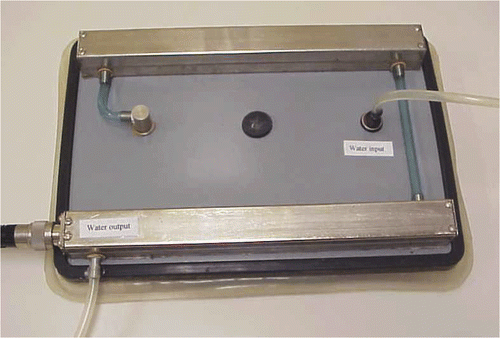
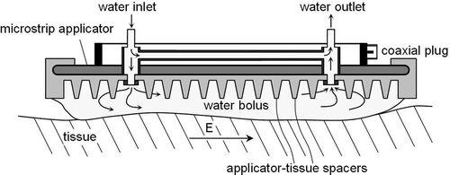
The Capacitive Contact Flexible Microstrip Applicator that was examined in this study is shown in . The applicator has an aperture of 20 cm × 29 cm and is operated at 70 MHz with an upper power limit of 300 W. A schematic representation of the mechanical construction of the applicator and its water cooling circuit is given in . A detailed description of the design and principle of operation of this type of applicator, a capacitive CFMA, is given by Gelvich and Mazokhin Citation[12]. This paper also describes inductive type CFMAs operating at higher frequencies and discusses specific properties of both types. The suppleness of the electrodes and the substrate enables some adaptation of the applicator to the cylindrical shapes of heated body parts. The applicator can only be bent around the axis parallel with the direction of the main E-field component of the irradiated EM-field. Coupling of the CFMA-70 applicator to the patient or phantom is realised by a water-filled silicon bolus that is fixed to the applicator. Through the bolus, water is circulated continuously to provide cooling of the skin and to avoid overheating of the applicator. The thickness of the water layer in the bolus can be varied between 0.5 and 3 cm. At a frequency of 70 MHz a variation in bolus thickness within this range is expected to have negligible influence on the SAR pattern Citation[13],Citation[14].
Phantoms and measurement techniques
Experiments to determine the E-field pattern of the CFMA-70 were performed in an elliptical phantom (cross-section 24 cm × 36 cm, length 84 cm) with a 2-mm PVC wall (). The phantom is filled with a 3 g/L saline solution. At 70 MHz and at 22°C this solution has a relative dielectric permittivity εr of 77 and a conductivity σ of 0.51 S/m. This conductivity is representative of the volume average of the conductivities of tissues within the human torso Citation[15]. Lagendijk and Molls Citation[16] recommend the applied phantom as a standard for deep body hyperthermia quality assurance. This phantom is generally applied in experiments with radiative hyperthermia systems for the treatment of deep-seated tumours such as the AMC four-waveguide array Citation[17]. As the applicators of this array operate at the same frequency as the CFMA-70 it was decided to use this phantom in this study as well.
Figure 3. Schematic representation of the experimental set-up used for measurement of the E-field pattern emanating from the CFMA-70. The elliptical phantom (cross section 24 cm × 36 cm, length 84 cm) has a 2-mm PVC wall and is filled with a saline solution. In the lower-right transparent representation the scanning planes are visualised.
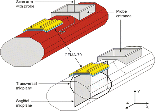
Fields scans were made using an E-field vector probe that was developed in cooperation with TNO-FEL laboratory (Netherlands Organization for Applied Scientific Research; Physics and Electronics Laboratory). The design is based on an electrically short dipole antenna (diameter 5 mm, length 5 mm) and an RF mixer in the sensor connected to a remote reference mixer Citation[18]. Low frequency signals from both mixers are compared to derive both phase and amplitude information. The probe is constructed using thin film technology, allowing component integration and small physical dimensions (diameter 5 mm, length 20 mm). The three orthogonal components of the E-field have to be measured separately: this can be done by rotating the probe to the orientation of interest. The overall accuracy of the amplitude and phase of the measured E-field is estimated to be better than 5% and 10 degrees respectively. Only in situations where the field strength is very low and the generator power and/or the amplification factor of the probe's signal processing unit have to be increased drastically to obtain an adequate signal the errors become significantly larger. This is a result of increasing noise levels and becomes apparent for instance when the y-component of the E-field is measured in the lower half of the sagittal midplane (defined below).
Measurements of the E-field were performed using a home built scanning system that was fixed to the probe entrance of the phantom. The applicator was placed on top of the phantom with its long axis parallel to the long axis of the phantom (). In this orientation the main field component of the applicator is in the z-direction. Scans were made in two planes perpendicular to the applicator (): the transversal midplane (XY-plane) and the sagittal midplane (YZ-plane). It is expected from the applicator design that in these planes the x- and/or y-component of the field will be close to zero and have negligible contribution to the SAR due to the predominant z-component of the field. To decide whether a component is negligible or not we used the criterion whether its contribution to the total SAR is (much) smaller than the uncertainty in the SAR due to uncertainty in field strength of the main E-field component. Coarse scans were made to verify negligibility of the x- and y-component in the transversal midplane and the x-component in the sagittal midplane. Detailed measurements were performed for the main field components: the z-component in the transversal midplane and the z- and y-component in the sagittal midplane. For these components horizontal and vertical scans were made with 2 cm distance between the scan lines. During scans the field strength is measured 1 to 4 times per mm dependent on the scanning speed. For analysis the scan data is reduced to 1 point per mm.
E-field measurements and data evaluation
Extensive E-field measurements are performed for a CFMA-70 applicator with a bolus thickness of 1 cm and 3 cm. As the probe has not been calibrated with respect to an absolute E-field standard all measurements are normalised to the E-field vector in the centre of the phantom (i.e. at 12 cm depth in the saline below the centre of the applicator). At this point the E-field was defined to be 100% in amplitude and zero degrees in phase. As the amplitude of the x- and y-component of the E-field is zero or close to zero at the centre of the phantom this means that the amplitude of the z-component is 100% at the normalisation point. Contour plots of the E-field patterns were calculated using a graphical program applying the ‘minimum curvature’ option, which generates the smoothest possible surface while attempting to respect the data as much as possible. Relative SAR distributions are calculated by summing the squares of the orthogonal field components and normalising the maximum SAR in the plane at 1 cm depth in the saline to 100%.
Contour plots of the E-field patterns are used for a qualitative comparison of the fields emanated by the CFMA-70 and by a 70 MHz waveguide. Waveguides with an aperture of 20 cm × 34 cm are used in the AMC four-waveguide array for the treatment of deep-seated tumours. The field pattern emanated by waveguides has been measured and evaluated according to the same procedure as described in the section Phantom and measurement techniques.
To enable a quantitative comparison with superficial applicators, the CFMA-434 applicators as published by Lamaitre et al. Citation[7], two parameters which are often used for characterisation of superficial applicators are derived from the SAR distributions. The quantitative parameters are the effective field size, EFS, and the effective heating depth, EHD. The EFS indicates the area of effective heating. It is defined by the 50% SAR contour in a plane at 1 cm depth from the surface of a (plane) homogeneous phantom. In this study, the EFS is represented by the width and length of the 50% SAR contour at 1 cm depth. These distances are along the major axes of the indicated plane and can be obtained from the contour plots of the transversal and sagittal midplane. The second quantitative parameter, the EHD, indicates the applicator's range of heating depth and is determined from a scan along the central y-axis, i.e. the percentage depth SAR or PDSAR. It is defined as the distance below 1 cm depth in the saline at which the SAR is reduced to 50% of the SAR at 1 cm depth. The EHD is identical to the penetration depth as defined in the QA guidelines of the European Society of Hyperthermic Oncology (ESHO) Citation[19], but was renamed by Lamaitre et al. Citation[7] to avoid confusion with the penetration depth δ (commonly used in physics as the distance over which the amplitude of the electric field is reduced by a factor of e). The EHD is determined with the CFMA-70 positioned on top of the elliptical phantom (as shown in ) as well as on its lateral side, which has a stronger curvature than the top side. In the latter situation the applicator is bent to fit to the curvature of the phantom. The EHD is also derived from an additional PDSAR measurement with the phantom filled with a muscle equivalent saline solution (4.75 g/L saline, εr = 77 and σ = 0.8 s/m at 22°C and 70 MHz). This additional measurement was performed as it is custom to use muscle equivalent phantoms for superficial applicators as opposed to the average torso mixtures that are applied for experiments with applicators operating at 70 MHz.
Clinical application of the CFMA-70
Patients have been selected for treatment with the new applicator based on tumour depth, 4 cm or more, which is regarded as too large to be treated adequately with CFMAs operating at 434 MHz. Hyperthermia was prescribed once weekly after radiotherapy, to a total of four treatments. The aimed tumour temperature between 41° and 43°C was to be maintained for 60 minutes. Temperatures were measured with invasive and non-invasive multi-point thermocouple probes. Each probe has 14 or 21 sensor points per probe with sensor spacing of 5, 7.5 or 10 mm. Due to the large number of sensor points it is not necessary to move the probe during treatment to increase the density of data points. The thermometry system and the measures to avoid artefacts are described by De Leeuw et al. Citation[20]. The probes are positioned perpendicular to the field direction as much as possible to minimise EM disturbances such as self-heating of the probe and cold-junction heating. Besides, the effect of self-heating is limited by determination of the temperatures at the end of a power-off period during a 25s/5s power on/off duty cycle. Cold-junction heating is prevented by application of ferrite suppression beads around the probe leads.
Results
E-field distribution and comparison to other AMC hyperthermia applicators
Coarse scans were made to verify negligibility of the x- and y-component in the transversal midplane and the x-component in the sagittal midplane. The scans showed that in large areas these components are below detection level and without exception their contribution to the local SAR is smaller than 4%. The criterion to decide whether an E-field component is negligible or not, is whether its contribution to the total SAR is (much) smaller than the uncertainty in the SAR due to uncertainty in field strength of the main field component: as the accuracy of the measured field strength is 5% the accuracy of the SAR is 10%. The contribution to the SAR of the x- and y-component in the transversal midplane and the x-component in the sagittal midplane is below 4%, and consequently these components are classified as negligible.
Contour plots of the main E-field components emanated by the CFMA-70 with a 1–cm thick bolus are shown in . The applicator (dark grey) and water bolus (light grey) are represented schematically. As the effect of the bolus thickness on the E-field pattern of the CFMA-70 appeared to be very small, the results for the experiment using a 3-cm bolus are not shown here. With increasing bolus thickness the single maximum does not split into two maxima. Contour plots of the SAR distribution emanated by the CFMA-70 with a 1-cm thick bolus are shown in . PDSAR profiles for the CFMA-70 positioned on the top and side of the phantom are demonstrated in for two different saline solutions. The penetration depth increases with increased curvature of the applicator or a decrease in saline concentration.
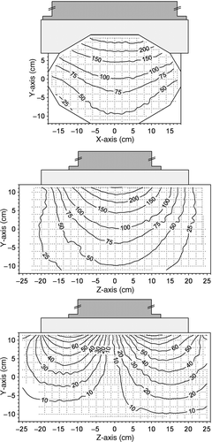
Figure 4. Contour plots of the E-field pattern emanating from the CFMA-70 applicator with a 1-cm thick bolus. The Z-component of the E-field in the origin of the phantom is normalised to 100%. Top graph: Z-component of the E-field in the XY-plane; Middle: Z-component of the E-field in the YZ-plane; Bottom: Y-component of the E-field in the YZ-plane. For all graphs the interval between contour lines is 50 and 25 for contours above and below 100 respectively.
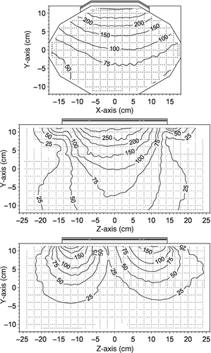
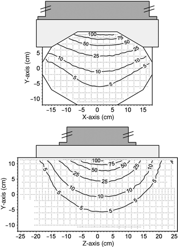
Contour plots of the E-field and SAR emanated by a waveguide operating at 70 MHz are shown in and respectively. PDSAR profiles from the waveguide are demonstrated in . The penetration depth of the CFMA-70 strongly resembles that of the waveguide. However, the effective power needed to achieve the same field strength along this line is 70% ± 20% higher for the CFMA-70 than for the waveguide. The EFS of the waveguide is smaller than the EFS of the CFMA-70. The difference in EFS is restricted to the z-direction: 26 cm for the CFMA-70 compared to 20 cm for the waveguide. Looking at the bottom plots of and it appears that the y-component of the field is more than twice as high for the CFMA-70 as it is for the waveguide.
Figure 5. Contour plots of the SAR patterns in the XY-plane and YZ-plane emanating from the CFMA-70 applicator with a 1-cm thick bolus. The SAR is normalised to 100% at 1 cm depth in the saline solution below the centre of the applicator.
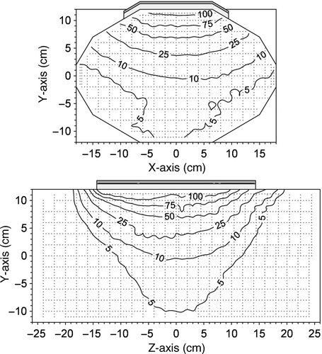
As stated already in the section on E-field measurements and data evaluation, the comparison of applicators for superficial hyperthermia is performed using two parameters: the effective heating depth (EHD) and the effective field size (EFS). For the CFMA-70 and two applicators that are currently applied at our department for superficial hyperthermia, CFMAs operating at 434 MHz, these parameters are given in . For the CFMA-70 the EFS (by definition at 1 cm depth from the surface) is 26 cm and 14 cm for the direction parallel and perpendicular to the major field direction, respectively. It should be noted that the extent of the EFS in the direction perpendicular to the major E-field is limited by the curved surface of the elliptical phantom. At 3 cm depth below the phantom surface the 50% SAR contour intersects with the phantom edge and is 20 cm wide. This means that the EFS approximately equals the size of the applicator (29 cm × 20 cm). In contrast, for CFMAs operating at 434 MHz the EFS is generally smaller than the aperture of the applicator.
Figure 6. PDSAR profiles, SAR as a function of distance below the phantom surface, for CFMA-70 and waveguide. Profiles are given for two different saline solutions. The CFMA-70 has been positioned on the top of the phantom surface (low curvature) as well as on its side (higher curvature). The SAR is normalised to 100% at 1 cm depth in the saline solution.
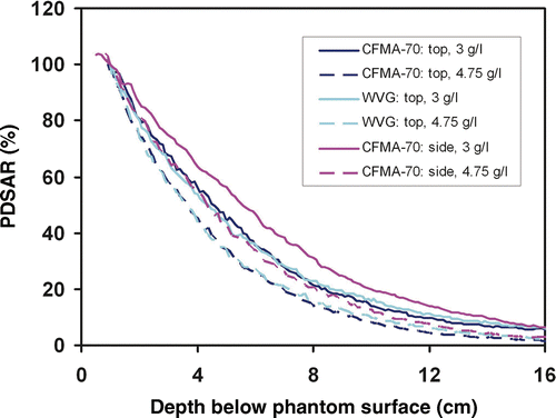
The EHD for the CFMA-70 is approximately 50%, or 1 cm, larger than for the CFMA-434 3H applicator. As Lamaitre et al. Citation[7] observed for the CFMA-434 3H applicator, the EHD increases for the CFMA-70 if it is placed on a surface with a smaller radius of curvature. As the applicator is bent around the axis parallel with the direction of the main E-component of the irradiated EM field some focussing will take place resulting in the increase of EHD.
Figure 7. Contour plots of the E-field pattern emanating from a 70 MHz waveguide with a 4-cm thick bolus. The Z-component of the E-field in the origin of the phantom is normalised to 100%. Top graph: Z-component of the E-field in the XY-plane; Middle: Z-component of the E-field in the YZ-plane; Bottom: Y-component of the E-field in the YZ-plane. For the top and middle graphs the interval between contour lines is 50 and 25 for contours above and below 100 respectively. For the bottom graph the interval between contour lines is 10.
Clinical experience
In a period of two years, six patients have been treated with the new applicator. All patients selected had advanced primary or recurrent breast cancer and were previously treated with radiotherapy, chemotherapy, and in three cases mastectomy. The extension of the tumours in depth was 5 cm or more. Temperatures were measured with multi-point thermocouples. Two to four non-invasive thermocouples were placed on the skin below the applicator (on average 45 points). They were positioned parallel to each other, 2 to 4 cm apart, with intention to cover the surface above the tumour. Zero to three invasive thermocouples were inserted into catheters that had been implanted previously (on average 30 points, see example in ). The orientation of 9 out of 11 invasive catheters was more or less parallel to the body surface/applicator plane. Two invasive catheters were implanted normal to this plane. The average distance of all invasive thermocouple points to the skin was 22.1 mm. The deepest measurement point varied from 19.5 to 64.5 mm (average 41.2 mm) among patients.
Figure 8. Contour plots of the SAR pattern in the XY-plane and YZ-plane emanating from the 70 MHz waveguide with a 4-cm thick bolus. The SAR is normalised to 100% at 1 cm depth in the saline solution below the centre of the applicator.
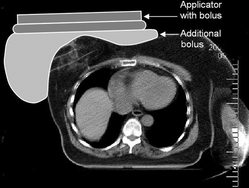
During the first treatment it appeared to be difficult to conform the shape of the antenna to the shape of the breast. This was a consequence of the fact that the applicator is less flexible than the 434 MHz CFMA applicators used for superficial hyperthermia and of the fact that the breast or tumour was vast, irregular and quite rigid. As the applicator did not make contact with the skin at several places up to 50% of the power was reflected resulting in poor heating of the tumour. To cope with this problem an additional bolus (28 cm × 38 cm) was placed on the breast for the next treatments. As the bolus is flexible the water will go downwards to the sides of the breast, adding almost no water layer between the top of the breast and the applicator as shown in . The application of the additional bolus resulted in a drastic decrease of the reflected power (now almost negligible) and better tumour heating. The application of an additional bolus was required for all patients.
Figure 9. Example of clinical application. CT-slice of the breast with a schematic representation of applicator and additional bolus. The applicator and bolus are kept in position using a belt around the thorax. Note the two catheter tracks in the breast for placement of thermocouple probes (third track not visible in this CT-slice).
As there was no previous experience with the treatment of large ‘superficial’ tumours using 70 MHz EM fields the temperature of the water circulating through the bolus was initially set at room temperature to prevent overheating of the skin. It appeared, however, that the water bolus temperature had a major impact on the temperature reached at the skin and the tissue directly below the skin. As a consequence no therapeutic temperatures could be achieved in this superficial area whilst there was sufficient power deposition even at a distance 6 to 8 cm from the applicator surface. During subsequent treatments the temperature of the water boli was increased using a thermostatic bath/circulator (Lauda). Experiments with the applicator/bolus positioned on top of a phantom at 37°C demonstrated that in the clinically applied range the water temperature within the bolus is 2° ± 0.5°C lower than the set temperature of the thermostatic bath. To a considerable extent this large temperature difference is caused by the heat exchanger, which has to be positioned between the thermostatic water bath and the water bolus circulation circuit: it is necessary to create a closed water circuit to control the water bolus thickness. The temperature of the thermostatic bath was set between 40° and 45°C (average 43.7°C), resulting in a water bolus temperature in the range 38° to 43°C (average 41.7°C). Even at these high bolus temperatures, in addition to the high power deposition at the body surface, the skin never reached temperatures much higher than 43.5°C. This indicates that the blood perfusion in the skin is huge and has a high cooling capacity: T10, T50 and T90 of the skin averaged over all patients are 41°C, 40°C and 39.1°C respectively.
Table I. Properties of the CFMA-70 and CFMA-434 applicators. Data regarding the CFMA-434 is taken from Lamaitre et al. Citation[7].
Evaluation of the invasive tumour temperature data showed that the temperature distributions were rather inhomogeneous and T50 was below the aimed therapeutic temperature: T10, T50 and T90 of the invasive tumour temperature points averaged over all patients are 41°C, 39.6°C and 38.5°C respectively.
In 10 out of a total of 21 sessions patients experienced pain. In one case complaints were related to the limited tolerance of the patient who experienced pain by pressure of the bolus and applicator. Other complaints were related to hot spots which in eight cases were treatment limiting and a reason to reduce the generator power or change the orientation of the applicator and bolus. Hot spots occurred mainly below the ends of the applicator in areas close to superficial bony structures such as the clavicle, sternum and ribs or in the axilla.
Discussion
E-field distribution and comparison to other AMC hyperthermia applicators
The CFMA-70 investigated in this study has properties of applicators applied for superficial hyperthermia as well as of applicators applied for deep hyperthermia: its geometry resembles that of superficial applicators Citation[7]; it operates at the same frequency as applicators used in AMC phased array systems for regional hyperthermia Citation[17]. The selection of the phantom applied in this study was driven by the frequency of the applicator under investigation aiming at appropriate interaction of the EM-field with the phantom material. The box-shaped and elliptical phantoms applied by Lamaitre et al. Citation[7] for evaluation of the SAR characteristics of three types of CFMAs for superficial hyperthermia are not applicable in this study. These phantoms are covered with a 1-cm thick artificial fat layer which mimics the dielectric properties of fat at a frequency of 434 MHz instead of 70 MHz. The elliptical phantom used in this study has often been used for measurements with applicators operating at 70 MHz, such as the 70 MHz waveguides of the AMC phased arrays. The elliptical phantom has a 2-mm PVC wall. Schneider et al. Citation[21] investigated the effect of the phantom wall material on the radiation efficiency of 70 MHz waveguides. They concluded that no obviously different experimental results were found between phantoms made from a 2 mm-PVC layer and one made from 1 cm artificial fat.
A direct comparison of the EFS of a CFMA-434 as published by Lamaitre et al. Citation[7] with those of the CFMA-70 is hampered by the fact that the saline solution used by Lamaitre et al. Citation[7] mimics a different tissue type as the saline solution applied in this study: Lamaitre et al. Citation[7] used a 6 g/L saline solution which mimics the properties of pure muscle at 434 MHz, whereas the saline solution applied in this study mimics a tissue whose conductivity equals the volume average of the conductivity of the tissues within the human torso. The higher conductivity of the saline applied by Lamaitre et al. Citation[7] may reduce the EFS slightly as the energy absorption in this solution is higher. On the other hand, the EFS for the 434 MHz CFMAs is measured on a flat-surfaced phantom and is not limited by the phantom. To enable a more direct comparison of the EHD the relatively simple PDSAR measurement is repeated for the CFMA-70 with the phantom filled with a saline solution which mimics the dielectric properties of pure muscle at 70 MHz (4.75 g/L saline, εr = 77 and σ = 0.8 S/m at 22°C), see also . In comparing the EHD of the CFMA-70 with that of the CFMA's operating at 434 MHz (see ), the only remaining difference in measurement set-up is the phantom wall. However, the latter will not result in different experimental results according to Schneider et al. Citation[21]. Taking this into account it can be concluded that the CFMA-70 has higher EHD than CFMA applicators operating at 434 MHz, as was desired. A comparison of separate E-field components cannot be made as these are not given by Lamaitre et al. Citation[7].
E-field pattern distortions, splitting of a single maximum into two or more maxima, may occur for microstrip applicators if the water bolus thickness exceeds a critical value. The occurrence of this effect has been demonstrated by Lamaitre et al. Citation[7] for CFMA-434 applicators. According to a theoretical analysis of this effect by Gelvich et al. Citation[14] the critical bolus thickness equals 11.8 cm for 70 MHz applicators. This value is well beyond the range applied clinically, 1–3 cm, and the distortions referred to have not been observed with this applicator. Regarding this specific property the CFMA-70 may act as a replacement for the CFMA-434 if the bolus thickness is difficult to control (e.g. uneven surfaces).
A comparison of the CFMA-70 to the waveguide operating at the same frequency shows that in the central XY-plane the E-field- and SAR-patterns of these applicators closely resemble each other. This also holds for the PDSAR profiles. However, differences in the E-field and SAR patterns are present in the YZ-plane. The y-component of the E-field directly below the applicator surface is more than twice as high for the CFMA-70 than it is for the waveguide, as can be seen in the bottom graph in and . This field component may induce hot spots in the subcutaneous fat layer or at tissue interfaces in the y-direction Citation[22]. Looking at the SAR distributions in and it appears that the EFS (range 50% at 1 cm below the phantom surface) in the z-direction is 26 cm for the CFMA and 20 cm for the waveguide. A significant contribution to the larger field size in this direction is caused by the aforementioned large y-component of the CFMA-70. The effective power needed to achieve equal field strength or SAR at a point along the central axis of the applicator is 70% ± 20% higher for the CFMA-70 than for the waveguide. This difference may have various causes. Firstly, the CFMA-70 distributes more of its energy into areas away from the central axis than the waveguide; it has a larger field size in this direction. Secondly, there are losses in components of the applicator. The manufacturer of the CFMA-70 explicitly states that during operation of the applicator the cooling system should be active to provide cooling of components. Even with active cooling, an increase in temperature of the metal ribs on top of the applicator (see ) was observed during operation at high power levels.
In the RTOG guidelines for clinical trials using hyperthermia Citation[23] it is stated that the selection of a heating device should be based on the SAR characteristics in a flat muscle equivalent phantom. Tumour margins should be encompassed by the 25% iso-SAR contour, taken relative to the maximum SAR within the phantom. The depth of this contour is given in , designated as RTOG25%muscle. It should be noted that opposed to phantoms proposed by the RTOG the elliptical phantoms as described earlier have been used for determination of this depth (applicator placed on top of the phantom).
The normalisation of the EM-field contour plots of the CFMA-70 () is unusual for superficial heating applicators. For single electromagnetic sources with exponential decay of power deposition into lossy tissue SAR is usually normalised at 1 cm below the surface, or 1 cm below a 1-cm fat layer. Of course, the choice of the normalisation point does not alter the form of the E-field contours. The reader can do a renormalisation by dividing the data in the contour plots by a fixed value: i.e. the relative E-field value at 1 cm below the phantom surface/100%. These values are 320%/100 for the CFMA-70 and 300%/100% for the waveguide.
Clinical experience
The inhomogeneity of the temperature distribution may be caused by inhomogeneous blood flow within the treated volume (large blood vessels, necrotic areas in previously treated tissue). Additionally, the irregular shape and structure of the breast may introduce inhomogeneities in the power deposition pattern. Vernon et al. Citation[6] published the results of an international study on the treatment of superficial localised breast cancer with or without hyperthermia. The maximum allowed tumour depth in their study was 4 cm (median 2 cm). They reported a median T50 and T90 of the invasive tumour temperature points of 42°C respectively 40.3°C. Whereas the homogeneity appears to be only slightly better, the achieved temperatures are considerably higher. The relatively low average temperatures achieved in our study are expected to be caused by the occurrence of hot spots which limit the applied generator power. The penetration depth of the EM-field appeared to be sufficient and the applied power levels, on average 220 W, were well below the maximum level for this applicator, 300 W.
In eight treatment sessions hot spots occurred that were treatment limiting. Possible cause for occurrence of these hot spots is the E-field component normal to the tissue surface. In their paper on CFMA applicators Gelvich and Mazokhin Citation[12] state that one of the most complicated problems common to capacitive applicators–fat tissue overheating–is basically solved, due to coplanar alignment of the capacitive plates, leading to mainly a tangential direction of the radiated EM field. Still, in the design of these applicators a compromise had to be made between large effective field size and low normal component and consequently a residual normal component does exist. According to Gelvich and Mazokhin Citation[12] the surface cooling abilities of these applicators are, as a rule, sufficient to avoid local fat overheating through this residual normal component. In the current study, however, it appeared that using a bolus temperature around 20°C results in tissue temperatures below the therapeutic range at least in the first few mm of the tissue. Van der Gaag et al. Citation[24] demonstrated that the range of tissue in which the temperature is influenced by the bolus is dependent on bolus type, thickness of the fat layer and blood perfusion rates: e.g. using a single applicator and a water bolus at 36°C the position of the temperature maximum varied from 5 mm up to 20 mm tissue depth with increasing thickness of the fat layer. Thus relatively high bolus temperatures are required to realise sufficient heating of the superficial tissue in areas where the normal component of the E-field is negligible. Consequently, low bolus temperatures cannot be used as a cooling feature for local hot spots caused by a large component of the E-field normal to the tissue surface.
During the first treatments it appeared to be difficult to conform the shape of the CFMA-70 to the shape of the breast. This was a consequence of the fact that most targets or tumours were large, irregular and quite rigid, but also of the fact that the applicator is less flexible than the 434 MHz CFMA applicators used for superficial hyperthermia. In all cases an additional bolus was positioned between applicator and patient to ensure adequate coupling of the EM waves to the patient. With this adjustment the set-up becomes bulkier and one might wonder whether a 70 MHz waveguide, with equal penetration depth, would give the same clinical results. Based on E-field distribution patterns this can indeed be expected. Besides, waveguides appeared to have a smaller E-field component normal to the tissue interface below the applicator edges and consequently lower probability of hot spots. The latter finding, however, is dependent on the size of the bolus below the waveguide. Wiersma et al. Citation[17] demonstrated that insufficient prolongation of the bolus beyond the waveguide edges results in an increase of fringing fields, i.e. a larger E-field component normal to the tissue interface. Such prolongation of the bolus would have seriously compromised patient comfort or would be impossible in four out of six patients selected for this study, thus a waveguide is no feasible alternative for this group of patients. For patients with large tumours in the intact breast, dedicated treatment units are being developed using a waveguide (our institute) or an RF-phased array as described by Wu et al. Citation[25]. For both systems the patient is in prone position with the breast being suspended in an open water bolus respectively surrounded by the applicator(s). These new units seem preferable over the CFMA-70 for the subset of patients with an intact breast, but still have to be tested clinically. For three out of six patients, however, these new systems would not have been an appropriate alternative. These patients underwent a mastectomy and had tumour invasion deep in the sternum or thoracic wall. The CFMA-70 seems an appropriate applicator for this last subset of patients, i.e. patients having a tumour growing inwards with extension in depth beyond the range of regular superficial applicators (though not deeper than 7 cm) and with limited irregularities of the body surface (e.g. no intact breasts).
Conclusions
The effective heating depth of the CFMA-70 is 50% larger than for the CFMA-434, adequate for the treatment of superficial tumours exceeding a depth of 4 cm. Its effective field size is 26 × 20 cm, which is larger than the EFS of an equal size CFMA-434. In contrast to the CFMA-434 the E-field pattern of this applicator is insensitive to the bolus thickness and thus may also be applied in situations where the bolus thickness is difficult to control (e.g. uneven surfaces). The CFMA-70 has a larger effective field size than waveguides operating at the same frequency. Compared to the waveguides 70% ± 20% more generator power is required to obtain an identical field strength at the central y-axis. The normal E-field component of the CFMA-70 is 100% larger than that of the 70 MHz waveguides. Because of this, hot spots may be induced at tissue interfaces in the direction normal to the applicator's surface.
So far, six patients were selected for treatment with the new applicator. The geometry of the volume to be heated was considered to be difficult to treat as in most cases the breast or tumour was large, irregular and quite rigid. Because of this it was difficult to conform the shape of the antenna to the shape of the breast and an additional flexible bolus was placed on the breast to cope with this problem. Although acceptable temperatures were realised in individual sessions, on average they were below the target level. The substantial surface irregularity of the heated volume may have contributed to this, but in several cases it was caused by hot spots. These occurred mainly below the ends of the applicator where the normal E-field component is largest.
Declaration of interest: The authors report no conflicts of interest. The authors alone are responsible for the content and writing of the paper.
References
- Myerson RJ, Perez CA, Emami B, Straube W, Kuske RR, Leybovich L, Von Gerichten D. Tumor control in long-term survivors following superficial hyperthermia. Int J Rad Oncol Biol Phys 1990; 18: 1123–1129
- Van der Zee J, Van der Holt B, Rietveld PJM, Hell PA, Wijnmaalen AJ, Van Putten WLJ, Van Rhoon GC. Reirradiation combined with hyperthermia in recurrent breast cancer results in a worthwhile local control. Br J Cancer 1999; 79: 483–490
- Albregts M, Hulshof MC, Zum Vorde Sive Vording PJ, Van Lanschot JJ, Richel DJ, Crezee H, Fockens P, van Dijk JD, Gonzalez Gonzalez D. A feasibility study in oesophageal carcinoma using deep loco-regional hyperthermia combined with concurrent chemotherapy followed by surgery. Int J Hyperthermia 2004; 20: 647–59
- van der Zee J, Gonzalez Gonzalez D, van Rhoon GC, van Dijk JD, van Putten WL, Hart AA. Comparison of radiotherapy alone with radiotherapy plus hyperthermia in locally advanced pelvic tumours: A prospective, randomised, multicentre trial. Dutch Deep Hyperthermia Group. Lancet 2000; 355: 1119–1125
- Overgaard J, Gonzalez Gonzalez D, Hulshof MC, Arcangeli G, Dahl O, Mella O, Bentzen SM. Randomised trial of hyperthermia as adjuvant to radiotherapy for recurrent or metastatic malignant melanoma. European Society for Hyperthermic Oncology. Lancet 1995; 345: 540–543
- Vernon CC, Hand JW, Field SB, Machin D, Whaley JB, van der Zee J, van Putten WL, van Rhoon GC, van Dijk JD, Gonzalez Gonzalez D, et al. Radiotherapy with or without hyperthermia in the treatment of superficial localized breast cancer: Results from five randomized controlled trials. International Collaborative Hyperthermia Group. Int J Radiat Oncol Biol Phys 1996; 35: 731–744
- Lamaitre G, Van Dijk JDP, Gelvich EA, Wiersma J, Schneider CJ. SAR characteristics of three types of contact flexible microstrip applicators for superficial hyperthermia. Int J Hyperthermia 1996; 12: 255–269
- Hulshof MC, Raaymakers BW, Lagendijk JJ, Koot RW, Crezee H, Stalpers LJ, Gonzalez Gonzalez D. A feasibility study of interstitial hyperthermia plus external beam radiotherapy in glioblastoma multiforme using the Multi ELectrode Current Source (MECS) system. Int J Hyperthermia 2004; 20: 451–463
- Van Wieringen N, van Dijk JD, Nieuwenhuys GJ, Snel CE, Cetas TC. Power absorption and temperature control of multi-filament palladium-nickel thermoseeds for interstitial hyperthermia. Phys Med Biol 1996; 41: 2367–2380
- Westermann AM, Wiedemann GJ, Jager E, Jager D, Katschinski DM, Knuth A, Vorde Sive Vording PZ, Van Dijk JD, Finet J, Neumann A, et al. Systemic Hyperthermia Oncologic Working Group. A Systemic Hyperthermia Oncologic Working Group trial. Ifosfamide, carboplatin, and etoposide combined with 41.8°C whole-body hyperthermia for metastatic soft tissue sarcoma. Oncology 2003; 64: 312–321
- Westermann AM, Jones EL, Schem BC, Van der Steen-Banasik EM, Koper P, Mella O, Uitterhoeve AL, de Wit R, Van der Velden J, Burger C, et al. First results of triple-modality treatment combining radiotherapy, chemotherapy, and hyperthermia for the treatment of patients with stage IIB, III, and IVA cervical carcinoma. Cancer 2005; 104: 763–770
- Gelvich EA, Mazokhin VN. Contact flexible microstrip applicators (CFMA) in a range from microwaves up to short waves. IEEE Trans Biomed Eng 2002; 49: 1015–1023
- Gelvich EA, Mazokhin VN, Troshin II, Van Dijk JDP. Quantitative evaluation of microstrip applicator's water bolus influence on SAR distribution. Proceedings of the 15th Annual Meeting of the European Society for Hyperthermic Oncology, Oxford, September, 1995. 10
- Gelvich EA, Mazokhin VN. Resonance effects in applicator water boluses and their influence on SAR distribution patterns. Int J Hyperthermia 2000; 16: 113–128
- Hagmann MJ, Levin RL, Turner PF. A comparison of the annular phased array to helical coil applicators for limb and torso hyperthermia. IEEE Trans Biomed Eng 1985; 32: 916–926
- Lagendijk JJW, Molls M. Conclusions deep body QA. COMAC-BME Bulletin 1991; 5: 95–96
- Wiersma J, Van Dijk JDP, Sijbrands J, Schneider CJ. The measurement of fringing fields in a radio-frequency hyperthermia array with emphasis on bolus size. Int J Hyperthermia 1998; 14: 535–551
- Schneider CJ, Kuijer JPA, Colussi LC, Schepp CJ, Van Dijk JDP. Performance evaluation of annular arrays in practice: The measurement of phase and amplitude patterns of deep body hyperthermia applicators. Med Phys 1995; 22: 755–765
- Hand JW, Lagendijk JJW, Bach A, Bolomey JC. Quality assurance guidelines for ESHO protocols. Int J Hyperthermia 1989; 5: 421–428
- De Leeuw AAC, Crezee J, Lagendijk JJ. Temperature and SAR measurements in deep-body hyperthermia with thermocouple thermometry. Int J Hyperthermia 1993; 9: 685–697
- Schneider CJ, Van Dijk JDP, Sijbrands J, Van Os RJ. Evaluation of the shape of the water bolus as a critical parameter for the amplitude ratios of the applicators in a radiative deep body hyperthermia system. Book of abstracts of the 13th ESHO conference. Brussels 1993; June: 46
- Guy AW. Analysis of electromagnetic fields induced in biological tissues by thermographic studies on equivalent phantom models. IEEE Trans Micro Theory Tech 1971; 19: 205–214
- Dewhirst MW, Phillips TL, Samulski TV, et al. RTOG quality assurance guidelines for clinical trials using hyperthermia. Int J Rad Oncol Biol Phys 1990; 18: 1249–1259
- Van der Gaag ML, De Bruine M, Samaras T, Van der Zee J, Van Rhoon GC. Development of a guideline for the water bolus temperature in superficial hyperthermia. Int J Hyperthermia 2006; 22: 637–656
- Wu L, McGough RJ, Arabe OA, Samulski TV. An RF phased array applicator designed for hyperthermia breast cancer patients. Phys Med Biol 2006; 51: 1–20
