Abstract
An anti-focus is defined as the point where the pressure amplitude is zero. As an active protection means in focused ultrasound, the anti-focus was researched through simulations. A 513 element, 1 MHz, 15 cm focal depth, spherical shape transducer with a central hold was used for the simulation. An anti-focus was implemented with two different approaches and the simulation results were compared. First, the interference among foci was compared to the summation of the individual focus fields. Second, the interference among anti-foci was compared to the multiplication of the individual anti-focus fields. The minimum distance between a focus and an anti-focus was determined by the comparison between intended control values and the simulation results. The field simulation results indicate that the minimum distance to control the field is approximately 3 mm in the lateral direction and 15 mm in the axial direction. The results also demonstrate that a specific zone can be effectively protected with the addition of anti-foci and that the field can be effectively implemented by switching type amplifier systems. Results demonstrate the potential for anti-foci to significantly reduce the collateral damage in focused ultrasound through improved field control.
Introduction
Focused ultrasound provides a non-invasive method for cancer therapy by causing thermal and cavitational damage to the target cells Citation[1–6]. The deposited heat energy from focused ultrasound can induce temperature elevation in tumours and causes the coagulation of the tumour cells Citation[1],Citation[4]. The violent cavitation can also create histotripsy in the tumour volume and results in complete annihilation of tumour cells Citation[5–6].
In order to use focused ultrasound effectively, a phased array system has been widely adopted due to its versatility Citation[7–9]. The fast electronic scanning of focal spots can produce heating patterns without mechanical movement of the transducer. Multiple foci can also be generated in order to shape the larger treatment zone freely Citation[9–10]. Hence, phased array systems can reduce the operation time greatly and increase the feasibility of ultrasound surgery in practice. Phased array systems also provide systematic planning for cancer treatment through simulation Citation[11–14]. The fast scanning acoustic beams combined with the bio-heat transfer model suggest a heat deposition pattern in tissue, and this can be used to optimise the focused ultrasound procedure.
In order to generate a multiple foci field, control points where the pressure amplitude reaches local maximum are used as the input. Based on the linear field approximation, the phase and amplitude conditions of each element of the phased array can be calculated by the pseudo-inverse method Citation[9–10]. This inverse problem can also be systematically solved by the iterative method to reduce the variation of amplitudes for each element Citation[10],Citation[15].
Although multiple foci seemed to be the best focusing method in focused ultrasound at first, previous studies have shown that the multiple foci do not provide a significant advantage over the fast scanning of a single focus in thermal treatment Citation[9],Citation[13]. This effect is mainly attributed to the slow increases of temperature as compared to scanning speed. Additionally, if histotripsy through cavitation is intended, splitting the energy with additional foci may not be an effective approach even with a large aperture, high power transducer. Therefore, the multiple foci field has not been used widely in focused ultrasound.
In practice, focused ultrasound with a phased array system can easily provide enough energy for cell damage with reasonable accuracy. One of the obstacles in the practical use of focused ultrasound has been the control of the collateral damage on important tissues: rectal wall, nerves, and urinary tract in prostate cancer treatment, and rib cage, hepatic artery, and portal vein in liver cancer treatment. Therefore, improved healthy tissue protection using focused ultrasound requires an advanced focusing method.
In order to minimise the damage on the specific tissue area, the ultrasound beam needs to be actively defocused around that area without causing significant change in the intended focal zone. Hence, an anti-focus is defined as the point where the pressure amplitude becomes zero in this presentation and systematic methods to generate an anti-focus were exploited. The nature of interference between foci and anti-foci was analysed through field simulation along with the limit of the combinational use of foci and anti-foci. Anti-focus is expected to provide advanced protection in focused ultrasound surgery.
Theory
The complex acoustic pressure at a point from a single frequency source is given by the Rayleigh-Somerfield integralwhere
, ρ is density of medium, c is the speed of sound, k is the wave number, s′ is the surface of source, u is the particle velocity normal to the surface of source, r is observation point, and r′ is source point, respectively Citation[10],Citation[16]. If an array of N elements generates M foci which are used as the control points in the field, one can write
where
is the position on the nth element of the array, un is the particle velocity of nth element of the array,
is the surface of nth element of the array, and rm is the mth control point.
This equation can be represented in matrix form aswhere
, and
, and H is the forward propagating operator with elements
The matrix H can be obtained based on the small element and far field approximation. Since H is a linear operator, the source condition u can also be determined by the pseudoinverse method from the control point pressure p. Practically speaking, the number of foci is always smaller than the array element number (M < N), so that the pseudoinverse of the matrix H can be obtained as far as the rank of the matrix is M. Although this condition might seem a random constraint, this condition can be easily met due to two factors. The first factor is that since array elements are often relatively large (>lambda/2), many phased array transducers used in therapeutic ultrasound are designed to avoid systematic grating lobes by locating elements in a pseudo random pattern Citation[17]. Due to the random location of each element, each row of the matrix H is usually linearly independent even with symmetrically located foci. The second factor is that the wavelength is short compared to the target volume. In focused ultrasound, the target volume is in the order of 1 cm when using a 1 MHz range centre frequency. Hence, the wavelength is approximately 1.5 mm and it is approximately 1 order of magnitude smaller than the target volume. Therefore, if the matrix H does not have rank M, the full rank matrix H can be obtained by shifting some of the foci approximately a half a wavelength of 0.8 mm without a significant change in the target volume.
Although the pseudoinverse method has been effectively used for both single focus and multiple foci, it cannot directly be used for anti-foci where the pressure amplitudes at all the control points are 0. Only one trivial source condition (u = 0) can be obtained if the pseudoinverse method is applied with the zero control condition (p = 0). In order to obtain a non-trivial solution, Equation 3 is modified aswhere H′ is a normalised sub matrix of H with respect to the ith column and the modified particle velocity
. The ith column is defined as the base of the calculation and it can be any column of the matrix. Since the right side of Equation 5 is not 0, a non-trivial solution can be obtained with the pseudoinverse method on Equation 5. Therefore, the amplitudes and phases of each element for anti-focus control points can be obtained with a one dimension reduced pseudoinverse (ODRPI). Additional dimension reduction can still provide non-trivial solutions. However, additional reduction of dimension will lead to zero velocity for the corresponding elements. In other words, those elements will not be used physically. Hence, additional dimension reduction is not considered further.
If only one anti-focus is required, Equation 3 can be further simplified as
Among M possible solutions of Equation 6, one of the special solutions that cannot be guaranteed from ODRPI is the equal amplitude solution. Equal amplitude for each element is a special case since high power driving systems for phased arrays generally adopt a switching power amplifier instead of linear amplifier in medical ultrasound imaging systems. Hence, the equal amplitude condition can be an important issue in the implementation. Assuming the anti-focus is located at the geometric focus of transducer, all the H(1, k) becomes identical and Equation 6 can be reduced aswhere C is a complex number obtained from the forward propagation matrix. The easiest method to obtain the equal amplitude solution from Equation 7 is assuming that H(1, k) is the (k − 1)th power of a complex number A as follows.
Therefore, the phases can be determined as shown in Equation 9.
If the combination of foci and anti-foci are used, a nontrivial solution of Equation 3 can be obtained directly from the pseudoinverse method. It is due to at least one value of p is not zero. Additionally, the assignment of 0 to the anti-focus and 1 to the focus point can be extended further to arbitrary values between [0, 1] to shape the ultrasound beam as necessary.
Method
Transducer
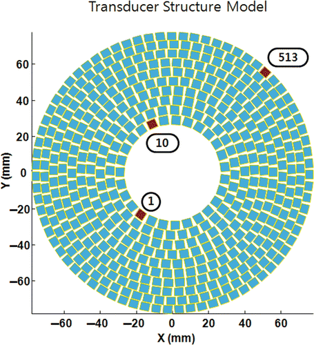
A 513 element, 1 MHz, the focal depth of 15 cm, spherical shape transducer with a central hole was used in this presentation. The aperture is approximately 15 cm in diameter and a central hole of approximately 5 cm in diameter was added for an ultrasound imaging probe. Each element is equal in size (5 mm × 5 mm) and is arranged in concentric rings at a pseudo random location to avoid a systematic grating lobe as can be seen in . This transducer type was chosen since it is a common extra-corporeal type transducer in focused ultrasound, and it was built for a future experiment Citation[17]. In the simulation, the speed of sound was assumed to be 1,540 m/s and tissue attenuation was not taken into account.
Figure 1. A 513 element transducer. The focal point is 150 mm from the surface of the transducer. Elements of 1st, 10th, and 513th were used as the basis to calculate the phase and amplitude conditions of anti-focus later in this presentation.
Although the attenuation coefficient is critical for heating and focusing in tissue, it was not considered in this presentation for two reasons. First, the attenuation coefficient in the human tissue needs to be considered with the tissue geometry. However, human skin is generally not attached to the transducer in focused ultrasound unlike ultrasound imaging, so the geometrical consideration needs to be simulated according to the treatment scenario which can be easily changed according to the target organ. The second reason is that the derating factor can be easily used in a single frequency condition and compensation can also be achieved if the path and tissue type are determined.
As the local tissue temperature increases, speed of sound (SOS) will be changed accordingly. The changes of SOS will cause thermal lens effect, defocusing, and shifting of the focal point Citation[18]. The previous research on thermal lens effect in focused ultrasound indicates that it strongly depends on the f-number of the transducer and it causes a 1 mm range discrepancy in the depth direction Citation[18]. However, SOS is assumed as a constant in this presentation due to two reasons. First, focused ultrasound generally starts from the deep tissue and moves toward the outside to preserve an acoustic window during the procedure. Hence, only local changes of SOS around the foci during the insonification will be critical. Second, the discrepancy in the depth direction is systematic in focused ultrasound, so that it might be compensated again later by iteration.
A single anti-focus
Two different methods were applied to calculate the phase and amplitude condition of each element for an anti-focus at the geometric focus point of the transducer. The first method was based on an M order complex root of 1 as shown in Equation 9, so that the amplitudes of all elements equal to 1. The other method was based on the ODRPI as shown in Equation 5. The choice of the base column can be a deterministic factor in the field, hence the 1st, the 10th, and the 513th elements were chosen in the simulation for comparison. The phase and amplitude conditions of the above four cases were compared. An additional field simulation was conducted with the phase condition from ODRPI and the amplitude modified to 1, in order to demonstrate the role of amplitude modulation in an anti-focus.
Multiple foci and multiple anti-foci
The multiple foci and anti-foci can interfere with each other, so that an unexpected field pattern may result due to their interference. The interference characteristics of multiple foci were analysed by the comparison of a multiple foci field and the summation of the individual single focus fields. On the other hand, the multiple anti-foci field was compared to the product of individual single anti-focus fields, since each anti-focus can be preserved by multiplication.
The combination of foci and anti-foci
Unlike multiple foci or multiple anti-foci, the field of the combination of foci and anti-foci cannot be approximated with a single operation on individual fields. Additionally, there are countless ways to combine even a small number of foci and anti-foci that can be formed for various purposes. Hence, the interference of foci and anti-foci was analysed for a simple case: four symmetrically located foci around a central anti-focus. This specific condition has been chosen since as an extreme case to protect important tissue while treating all the surrounding area. The distance between each focus and anti-focus was used as a variable. The minimal distance, which satisfies the intended control values of 1 and 0 at the control point, between a focus to the anti-focus was calculated.
Additionally, the reduction or relocation of a side lobe of a focus was demonstrated with symmetrically located anti-foci around a central focus. This specific case was chosen for the purpose of possible application of anti-foci in the ultrasound imaging.
An application example of multiple foci with anti-focus
For thermal damage effects, direct temperature control is more critical than the beam pattern. Hence, temperature-focused studies need to be conducted. The bio-heat transfer equation can be a model for simulation research as in the previous studies Citation[19–20]. A simple application of the anti-focus was tested in two dimensions with the bio-heat transfer equation and the thermal dose calculation based on Equations 10 and 11.where
, ρt is the tissue density, Ct is the specific heat of tissue, kt is thermal conductivity of tissue, ρb is blood density, Cb is the specific heat of blood, W is blood perfusion rate, α is the attenuation coefficient of tissue, p is the acoustic pressure amplitude, T is temperature, and Ta is the ambient temperature of human body, respectively.
where D(x, y, z) is the local thermal dose, and tT is the duration, respectively. The parameters used in the simulation are as shown in Citation[18],Citation[21].
Table I. Parameters for bio heat transfer equation.
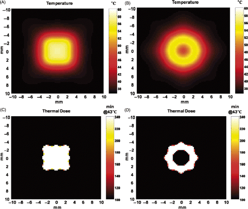
For the comparison of thermal damage results, two multiple foci fields and two multiple foci with anti-foci fields were simulated. The arrangement of foci and anti-foci of individual fields are described in .
Table II. Foci and anti-focus arrangement for an application example.
First, Fields I and II were insonified for 20 m/s each in an alternating pattern for a total duration of 2.8 s. The temperature distribution was calculated based on Equation 10 for 8 s starting from the insonification. The accumulated thermal dose was obtained from the temperature simulation result with Equation 11. Similarly, the temperature distribution was also computed for 8 s with alternating insonification (20 m/s each) of Fields III and IV for a total duration of 2.8 s. The accumulated thermal dose was also calculated. The resultant temperature distributions and the thermal doses were compared.
Results
A single anti-focus
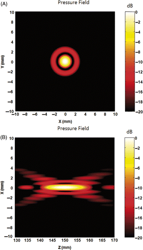
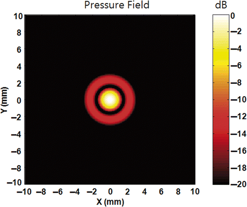
As a comparative measure, a single focus field simulation is conducted as shown in . The simulation results indicate the full width half maximum (FWHM) focus size is approximately 1.8 mm in the lateral direction and 15 mm in the axial direction, respectively. The first side lobe is approximately 12 dB down compared to the main focus amplitude. Its peak location is approximately 2.4 mm and it extends approximately 3 mm away from the focus point in lateral direction.
Figure 2. Pressure field at the geometric focus of the transducer with the equal phase and amplitude condition on each element. (A) is the x-y plane (lateral) field and (B) is the x-z plane (axial) field.
shows pressure fields of an anti-focus simulated with different phase and amplitude conditions. are the x-y and y-z plane field, respectively, based on the phase and amplitude conditions from an M-order complex root of 1. As can be seen in , the anti-focus was achieved by the systematic shift of the focus point in the axial direction. Since the goal is providing protection without causing significant change in any focus, the shift of the focus is not a proper solution.
Figure 3. Pressure field of an anti-focus located at (0, 0, 150). (A) and (B) are the x-y and y-z plane field, respectively, obtained from M-order complex root of 1. (A) and (B) show that the zero pressure point is achieved by systematic shifting of the focus point. (C) and (D) are x-y and y-z plane field, respectively, obtained using ODRPI with the first element as the basis. (E) and (F) are x-y plane fields obtained using ODRPI with the 10th and the 513th element as the basis, respectively. (C) to (F) show the anti-focus with ODRPI is not a systematic shift of a focus. Additionally, the choice of the base element determines the overall shape of the field around the anti-focus point.
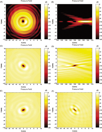
are the x-y and y-z plane field, respectively, obtained with ODRPI when the first element was used as the base element. Since the pressure at the anti-focus is zero, the field is displayed with respect to the maximum pressure value in dB. As can be seen in , the field around anti-focus does not have strong side lobes and the anti-focus appears as a singular point where the pressure around it does not change smoothly. Although it seems quite different compared to , , the anti-focus in the amplitude map always appears as a singular point since there is sign change around the zero pressure point. Additionally, the appearance of the anti-focus becomes much more distinct since the dB scale utilises the relative amplitude ratio in the logarithmic scale, which results in −∞ dB at the anti-focus. shows that the extent of the low amplitude area in the axial direction is in the order of 10 mm compared to 2–3 mm in the lateral direction.
The effect of the base element location can be deduced from the comparison of . As can be seen in those figures, the field shape becomes closer to circular as the base element approaches the centre. Additionally, the direction of the elongation of the field is perpendicular to the location of the base element.
show the amplitude and phase conditions used for an anti-focus simulation. As can be seen in , the amplitude of only the base element is 1 and those of all other elements are nominal in case ODRPI method is used. And the phase values are almost identical considering 2π periodicity. This indicates that the calculated phase condition for an anti-focus is identical to that for a focus. A focus instead of an anti-focus was generated by simply replacing the amplitude to a single value of 1 as shown in .
Figure 4. Amplitude and phase of each element for an anti-focus. (A) shows the normalised amplitude of each channel to generate the anti-focus, and (B) shows the relative phase of each channel. Only the amplitude of the base element is 1 and the amplitudes of all other elements are nominal and the phases are identical considering 2π periodicity, if ODRPI is used. On the other hand, an anti-focus can also be achieved by simple phase modulation with equal amplitude, if M-order complex root of 1 is used.
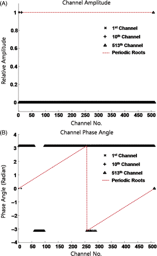
Figure 5. The simulated field obtained with phased conditions from ODRPI and the amplitude modified to 1. If each element is driven with phases from ODRPI and equal amplitudes, a focus can be generated instead of an anti-focus. Hence, the amplitude modulation is the main factor for a single anti-focus, if ODRPI is used.
Multiple foci and multiple anti-foci
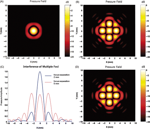
shows the four foci field simulation. As can be seen in , the four foci seem to merge and form a new focus when the control points are close enough. However, closer inspection of the field map indicates that the actual pressure at the control points is still 1, which was the intended control value as seen in . A new focus point was formed due to strong interference among four foci, and the pressure at the interference point simply happened to be larger than those at the intended control points. Hence, individual focus fields are still independent although it appears not to be. This characteristic can be clearly visualised by the comparison between a field with multiple foci and the summation of individual single focus fields, as shown in . The two fields are almost identical except for a scale factor. Therefore, the multiple foci field can be approximated by the summation of individual focus fields.
Figure 6. Pressure field of multiple foci. (A) is the field when foci are located at (1, 0, 150), (0, 1, 150), (−1, 0, 150), and (0, −1, 150). (B) is the field when foci are placed at (2.5, 0, 150), (0, 2.5, 150), (−2.5, 0, 150), and (0, −2.5, 150). Figures indicate a new focus can be formed by closely located foci. (C) shows a line of field at y = 0 from (A) (B). As can be seen in (C), the intended pressure value 1 was achieved at the control points (intended foci). This implies the individual pressure fields are independent from each other. (D) is the summation of the four single focus fields. The comparison between (B) and (D) indicates that the multi-foci field is almost identical with the summation of individual focus fields.
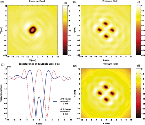
Unlike the multiple foci, the field simulation of multiple anti-foci does not show strong interference regardless of the distance between individual anti-focus, as can be seen in . Since zero pressure amplitude at the control points can be preserved by the multiplication operator, the multiple anti-foci field is compared to the product of individual anti-focus fields as shown in . Although the two fields are not identical, they show very similar field characteristics around the anti-foci. This is due to the amplitude of the field around an anti-focus slowly decreasing after it reaches the maximum point. This indicates that multiple anti-foci can be approximated with multiplication of individual anti-focus fields.
Figure 7. Pressure field of multiple anti-foci. (A) is the field when foci are located at (1, 0, 150), (0, 1, 150), (−1, 0, 150), and (0, −1, 150). (B) shows the field when foci are placed at (2.5, 0, 150), (0, 2.5, 150), (−2.5, 0, 150), and (0, −2.5, 150). (C) shows a line of field at y = 0 from (A) and (B). Figures indicate anti-foci are independent to each other. The comparison between (B) and (D) shows that the multiple anti-foci field can be approximated with a product of individual anti-focus fields.
The combination of foci and anti-foci
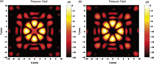
shows the simulated field characteristics of four symmetrically located foci around a central anti-focus. As can be seen in , the intended value at the control points can be achieved by separating foci with the anti-focus by approximately 3 mm which is the end of the first side lobe of the transducer. If the distance is shorter, the intended focus points are pushed away from the anti-focus as indicated in . Additionally, the pressure amplitude at the shifted focus increases, too. confirms the minimal distance is approximately the end of the first side lobe. By simply increasing the frequency three times and reducing the focal size three times, the intended pressure values at the control points can be achieved at one third of the distance.
Figure 8. Pressure field of the combination of an anti-focus and multiple foci. With a single anti-focus at the (0, 0, 150), three different sets of four foci are applied to create (A)–(C). The first set is [(1, 0, 150), (0, 1, 150), (−1, 0, 150), (0, −1, 150)], the second set is [(2.5, 0, 150), (0, 2.5, 150), (−2.5, 0, 150), (0, −2.5, 150)], and the third set is [(3, 0, 150), (0, 3, 150), (−3, 0, 150), and (0, −3, 150)], respectively. (D) shows the centre line of the pressure field at y = 0. As shown in (D), if the distance between focus and anti-focus reaches 3 mm which is approximately the end of the first side lobe, the interference at control points becomes nominal.
![Figure 8. Pressure field of the combination of an anti-focus and multiple foci. With a single anti-focus at the (0, 0, 150), three different sets of four foci are applied to create (A)–(C). The first set is [(1, 0, 150), (0, 1, 150), (−1, 0, 150), (0, −1, 150)], the second set is [(2.5, 0, 150), (0, 2.5, 150), (−2.5, 0, 150), (0, −2.5, 150)], and the third set is [(3, 0, 150), (0, 3, 150), (−3, 0, 150), and (0, −3, 150)], respectively. (D) shows the centre line of the pressure field at y = 0. As shown in (D), if the distance between focus and anti-focus reaches 3 mm which is approximately the end of the first side lobe, the interference at control points becomes nominal.](/cms/asset/ea3eb61b-7504-48ac-9757-1b2f4ed5db29/ihyt_a_419009_f0008_b.gif)
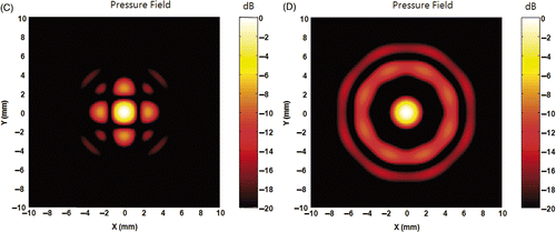
Figure 9. Field map of the combination of an anti-focus and foci at higher frequency and modified amplitude condition. (A) shows the field with an anti-focus and four foci at [(1, 0, 150), (0, 1, 150), (−1, 0, 150), (0, −1, 150)] with a frequency of 3 MHz. (A) confirms that the recommended distance between anti-focus and focus is approximately the end of the first side lobe of the transducer. (B) was obtained by modifying the amplitude condition to 1. An anti-focus and four foci were successfully created as intended with additional side lobes. This indicates that a switching type amplifier can be effectively used with anti-foci.
![Figure 9. Field map of the combination of an anti-focus and foci at higher frequency and modified amplitude condition. (A) shows the field with an anti-focus and four foci at [(1, 0, 150), (0, 1, 150), (−1, 0, 150), (0, −1, 150)] with a frequency of 3 MHz. (A) confirms that the recommended distance between anti-focus and focus is approximately the end of the first side lobe of the transducer. (B) was obtained by modifying the amplitude condition to 1. An anti-focus and four foci were successfully created as intended with additional side lobes. This indicates that a switching type amplifier can be effectively used with anti-foci.](/cms/asset/b860a342-1c9b-4717-9095-982a45a7362c/ihyt_a_419009_f0009_b.gif)
As shown in and , the amplitude modulation is the main factor for generating a single anti-focus when the ODRPI method is used. However, amplitude modulation is not the main factor in the case of the combination of foci and anti-foci, as shown in . Even after replacing all the amplitudes to 1, the intended field pattern can still be approximated with an increase of side lobes. Hence, driving the medical ultrasound system with a switching power amplifier can effectively implement the combinational field of foci and anti-foci.
As can be seen in , the addition of four anti-foci around a focus at a distance of 3 mm is not effective at reducing the first side lobe. Fortunately, the anti-foci need to be located in a symmetric pattern around a focus in order to reduce the first side lobe completely. Hence the focus point is not affected by the closely located anti-foci as shown in . Although reduction of the first side lobe seemed plausible with additional anti-foci around a focus, the additional anti-foci can cause further problems. shows the resultant field when eight anti-foci were used around a focus. The first side lobe was pushed away from the original point but the amplitude of it increases approximately 3 dB. Hence, the resultant field can be expressed as the relocation of the first side lobe instead of the reduction. However, this simulation result is conducted in a steady state condition. Therefore, it cannot be directly translated for the broadband short pulse condition in ultrasound imaging with frequency dependent attenuation. Considering a short pulse condition, the side lobe reduction will be less at the beginning and the end of the pulse due to the lack of destructive interference.
Figure 10. Side lobe relocation by anti-foci around a focus. A set of anti-foci were applied to relocate side lobe with a focus at (0, 0, 150). (A) is the result of four anti-foci [(3, 0, 150), (0, 3, 150), (−3, 0, 150), (0, −3, 150)]. (B) is the result of four anti-foci [(2.5, 0, 150), (0, 2.5, 150), (−2.5, 0, 150), (0, −2.5, 150)]. (C) is the result of four anti-foci of [(1.77, 1.77, 150), (−1.77, 1.77, 150), (1.77, −1.77, 150), (−1.77, −1.77, 150)]. (D) is the pressure field result with eight anti-foci [(2.5, 0, 150), (0, 2.5, 150), (−2.5, 0, 150), (0, −2.5, 150), (1.77, 1.77, 150), (−1.77, 1.77, 150), (1.77, −1.77, 150), (−1.77, −1.77, 150)]. Addition of anti-focus at the 3 mm does not reduce the side lobe greatly as shown in (A). However, placing anti-foci at the peak location of first side lobe can locally reduce the amplitude of side lobe as can be seen in (B) and (C). Unfortunately, anti-foci cannot be added without causing strong interference and the side lobe is relocated instead of total reduction.
![Figure 10. Side lobe relocation by anti-foci around a focus. A set of anti-foci were applied to relocate side lobe with a focus at (0, 0, 150). (A) is the result of four anti-foci [(3, 0, 150), (0, 3, 150), (−3, 0, 150), (0, −3, 150)]. (B) is the result of four anti-foci [(2.5, 0, 150), (0, 2.5, 150), (−2.5, 0, 150), (0, −2.5, 150)]. (C) is the result of four anti-foci of [(1.77, 1.77, 150), (−1.77, 1.77, 150), (1.77, −1.77, 150), (−1.77, −1.77, 150)]. (D) is the pressure field result with eight anti-foci [(2.5, 0, 150), (0, 2.5, 150), (−2.5, 0, 150), (0, −2.5, 150), (1.77, 1.77, 150), (−1.77, 1.77, 150), (1.77, −1.77, 150), (−1.77, −1.77, 150)]. Addition of anti-focus at the 3 mm does not reduce the side lobe greatly as shown in (A). However, placing anti-foci at the peak location of first side lobe can locally reduce the amplitude of side lobe as can be seen in (B) and (C). Unfortunately, anti-foci cannot be added without causing strong interference and the side lobe is relocated instead of total reduction.](/cms/asset/43006068-ab19-4463-a183-9d6f266d8e03/ihyt_a_419009_f0010_b.gif)
An application example of multiple foci with anti-focus
The 2D simulation results are presented in . As seen in , multi-foci fields can cover a large area. However, it does not provide the fine control necessary for minimising tissue damage, which can be a critical factor in practice. On the other hand, the simple addition of anti-foci created the protected area at the centre of the foci without any cooling time as shown in . These simulation results indicate that anti-foci can provide an active protection measure in focused ultrasound.
Figure 11. An application example of anti-focus. (A) A simulated temperature distribution computed 8 seconds after alternating insonification of 20 m/s for Field I and Field II for a total duration of 2.8 s. (B) A simulated temperature distribution computed 8 seconds after alternating insonification of 20 m/s for Field III and Field IV for a total duration of 2.8 s. The peak pressure amplitude is 5 MPa in all four cases. (C) The accumulated thermal dose of (A) and (D) is the accumulated thermal dose of (B).
Discussion
Although the interference between foci and anti-foci has not been fully covered in this presentation, the simulation results indicate that improved tissue protection can be achieved. Anti-foci can be placed near foci and the driving condition of each element can be obtained with the pseudoinverse method. Additionally, the obtained condition can be effectively used with switching type amplifying systems found in medical ultrasound systems. For reasonable control of the pressure field for therapeutic purposes, the distance between anti-focus and focus in the lateral direction is recommended to be greater than the location of the end of the first side lobe.
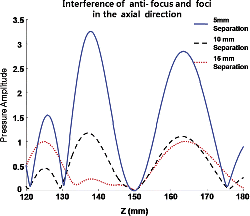
On the other hand, the interference between an anti-focus and a focus becomes nominal if they are separated more than 15 mm in the axial direction, as can be seen in . Unlike the distance in the lateral direction, the minimal distance between an anti-focus and a focus approximately matches the size of FWHM focus of the transducer.
Figure 12. Interference between anti-focus and foci in the axial direction. The intended control values can be obtained when the foci are located approximately 15 mm away from an anti-focus.
As shown in previous studies Citation[10],Citation[15], iterative weighting can be used in the pseudoinverse method to reduce the variation of amplitudes as:where W is a N × N weighting matrix, H*t is the conjugate transpose of H Citation[10]. The weighting matrix element can be determined as follows:
Unlike the multiple foci cases, the number of iterations can be a significant factor, as can be seen in . If an odd number of iterations was conducted, the anti-focus almost disappears. However, if an even number of iterations was conducted, an anti-focus can be effectively formed. This result appears due to the weighting factor of 1 over the absolute value of the element amplitude. Generally, all the component values of the forward propagation matrix H in Equation 4 are very large (e.g., in the order of 1012–1013), so that the corresponding component values of its pseudoinverse is very small. Since iteration is required, the order of component values for the forward calculation and its pseudoinverse matrix is reversed at each iteration step. In the calculation for only multiple foci, this factor does not seem to be critical since the objective is to determine the condition where the foci are local maximum pressure points. However, this factor may become critical in the anti-foci case since anti-foci are supposed to have the precise amplitude of zero. Hence, the number of iterations should be carefully chosen for anti-foci.
Figure 13. Field simulation of four foci around an anti-focus obtained by iterative weighting. (A) The field after 7 iterations, and (B) the field after 8 iterations, respectively.
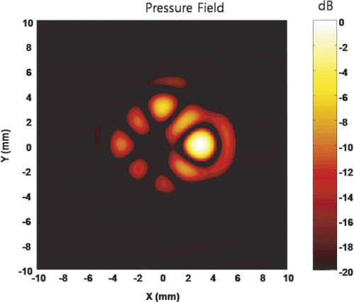
In the calculation of the phase and amplitude condition of elements with the pseudoinverse approach, the control value for the anti-foci was 0 and that for the foci was 1. This implies that any value between 0 and 1 can be used as necessary and the actual pressure field can be generated by multiplication of a scale factor. demonstrates that an arbitrary control values of 1, 0.5, 0.3, 0.2, and 0 at (3, 0, 150), (0, 3, 150), (−3, 0, 150), (0, −3, 150), and (0, 0, 150) can be successfully obtained. Therefore, more accurate field pattern can be generated with a constraint of interference between each control point.
Figure 14. Generation of arbitrary shape field. The field was obtained with the condition of an anti-focus at the (0, 0, 150), a focus at the (3, 0, 15) with the control value of 1, a focus at the (0, 3, 15) with the control value of 0.5, a focus at the (−3, 0, 15) with the control value of 0.3, and a focus at the (0, −3, 15) with the control value of 0.2. Any value between 0 and 1 can be used successfully to create an arbitrary field as necessary.
The reduction of side lobes can improve image quality, since ultrasound imaging generally operates over a 40 dB dynamic range and the first side lobe cannot be over −40 dB. Unfortunately, the preliminary simulation results can only relocate the first side with the aid of anti-foci. However, it might be still useful, since ultrasound imaging is a transmitting and receiving system. In other words, the first side lobe might be reduced by the proper combination of different transmitting and receiving patterns with the transducer array.
Although 2D simulations of the given application example indicate great improvement for protection around a damage zone with anti-foci, a 3D calculation is required for practical use of anti-foci. Currently, faster and more flexible 3D simulation tools are under development for future use. More thorough application studies of anti-foci will be presented in subsequent presentations.
As mentioned in Methods above, a constant SOS and zero attenuation were assumed in most cases except for the temperature simulation shown in . Since the changes of SOS can systematically cause focal spot relocation, it needs to be investigated in detail. Additionally, the non-linear effect in focused ultrasound can also cause different thermal deposition. Hence, time domain analyses of the field with attenuation and non-linear factors will be required for the verification of the applications of anti-foci.
Experimental verification is also required for anti-foci. The authors currently are building the driving system for the phased array transducer. The experimental verification is expected to be conducted in the near future.
Conclusion
The anti-focus, where the acoustic pressure is zero, was studied with field simulations as an active protection means of important tissue. The addition of anti-foci can interfere with the given foci with the distance between foci and anti-foci as the main factor. The recommended minimal distance between the foci with anti-foci is approximately the location of the end of the first side lobe from the focus. Anti-focus is expected greatly to improve the control of collateral damage in the focused ultrasound.
Acknowledgement
This work is supported by the Ministry of Knowledge Economy, Republic of Korea.
Declaration of interest: The authors report no conflicts of interest. The authors alone are responsible for the content and writing of the paper.
References
- Fry WJ, Mosberg WH, Barmard JW, Fry FJ. Production of focal destructive lesions in the central nervous system with ultrasound. J Neurosurg 1954; 11: 471–478
- Linke CA, Carstensen EL, Frizzell LA, Elbadawi A, Fridd CW. Localized tissue destruction by high-intensity focused ultrasound. Archives Surgery 1971; 107: 887–891
- ter Haar GR. Ultrasound focal beam surgery. Ultrasound Med Biol 1995; 21: 1089–1100
- Watkin NA, Morris SB, Rivens IH, ter Haar GR. High-intensity focused ultrasound ablation of the kidney in a large animal model. J Endourology 1997; 11: 191–196
- Parsons JE, Cain CA, Abrams GD, Fowlkes JB. Pulsed cavitational ultrasound therapy for controlled tissue homogenization. Ultrasound Med Biol 2006; 32: 115–129
- Tran BC, Seo J, Hall TL, Fowlkes JB, Cain CA. Effects of contrast agent infusion rates on thresholds for tissue damage produced by single exposures of high-intensity ultrasound. IEEE Trans UFFC 2005; 52: 1111–1120
- Cain CA, Umemura SI. Concentric-ring and sector-vortex phased-array applicators for ultrasound hyperthermia. IEEE Trans MTT 1986; MTT-34: 542–551
- Daum DR, Hynynen K. A 256-element ultrasonic phased array system for the treatment of large volumes of deep seated tissue. IEEE Trans UFFC 1999; 46: 1254–1268
- Fan X, Hynynen K. A study of various parameters of spherically curved phased arrays for noninvasive ultrasound surgery. Phys Med Biol 1996; 41: 591–608
- Ebbini ES, Cain CA. Multiple-focus ultrasound phased-array pattern synthesis: Optimal driving-signal distributions for hyperthermia. IEEE Trans UFFC 1989; 36: 540–548
- McGough RJ, Kessler ML, Ebbini ES, Cain CA. Treatment planning for hyperthermia with ultrasound phased arrays. IEEE Trans UFFC 1996; 43: 1074–1084
- Wan H, Ebinni ES, Cain CA. Ultrasound surgery: Comparison of strategies using phased array systems. IEEE Trans UFFC 1996; 43: 1085–1098
- Wan H, Aarsvold J, O’Donnell M, Cain CA. Thermal dose optimization for ultrasound tissue ablation. IEEE Trans UFFC 1999; 46: 913–928
- McGough RJ, Ebbini ES, Cain CA. Direct computation of ultrasound phased-array driving signals from a specified temperature distribution for hyperthermia. IEEE Trans Biomed Eng 1992; 39: 825–835
- Wang H, Ebbini ES, Cain CA. Computationally efficient algorithm for control of ultrasound phased array hyperthermia applicators based on a pseudo-inverse method. IEEE Trans UFFC 1990; 37: 247–277
- Ocheltree K, Frizzell L. Sound field calculation for rectangular sources. IEEE Trans UFFC 1989; 36: 242–249
- Kluiwstra JA, McGough RJ, Hamilton JD, O’Donnell M, Cain CA. Design strategies for therapeutic ultrasound phased arrays. SPIE Med Imaging Symp Proc 1997; 3037: 62–70
- Connor CW, Hynynen K. Bio-acoustic thermal lensing and nonlinear propagation in focused ultrasound surgery using large focal spots: A parametric study. Phys Med Biol 2002; 47: 1911–1927
- Pennes HH. Analysis of tissue and arterial blood temperatures in the resting human forearm. J Appl Physiol 1948; 1: 93–122
- Sapareto S, Dewey W. Thermal dose determination in cancer therapy. Int J Rad Oncol Biol Phys 1984; 10: 787–800
- Hong W. Thermal dose optimization for ultrasound tissue ablation. PhD Thesis submitted to University of Michigan, Ann Arbor 1999
