Abstract
Purpose: To improve the efficacy of hyperthermia treatment, a novel method of non-invasive measurement of changes in body temperature is proposed. The proposed method is based on phase changes with temperature in electromagnetic waves in a heating applicator and the temperature dependence of the dielectric constant. An image of the temperature change inside a body is reconstructed by applying a computed tomography algorithm. This method can be combined easily with a heating applicator based on a cavity resonator and can be used to treat cancer effectively while non-invasively monitoring the heating effect. In this paper the phase change distributions of electromagnetic waves with temperature changes are measured experimentally, and the accuracy of reconstruction is discussed.
Materials and methods: The phase change distribution is reconstructed by using a prototype system with a rectangular aluminum cavity resonator that can be rotated 360° around an axis of rotation. To make measurements without disturbing the electromagnetic field distribution, an optical electric field sensor is used. The phase change distribution is reconstructed from 4-projection data by using a simple back-projection algorithm.
Results: The paper demonstrates that the phase change distribution can be reconstructed. The difference between phase changes obtained experimentally and by numerical analysis is about 20% and is related mainly to the limited signal detection sensitivity of electromagnetic waves.
Conclusions: A temperature change inside an object can be reconstructed from the measured phase changes in a cavity resonator.
Introduction
Hyperthermia is an effective therapeutic technique used in conjunction with radiotherapy or carcinostatic agents. However, some researchers have been sceptical about the clinical usefulness of hyperthermia Citation[1], Citation[2]. One reason for this is that it is difficult to administer heat treatment to a local region in the living body to attain the desired temperature in basic clinical or in vivo experiments. Moreover, internal body temperature changes cannot be easily measured non-invasively and precisely. Hence, it is indispensable to develop a method and equipment that can perform quantitative temperature measurement in vivo.
Although many non-invasive thermometry methods using the temperature dependence of acoustic velocity, attenuation of ultrasound, impedance, and so on Citation[3] have been examined over many years, a satisfactory method of measuring the temperature inside a living body has not been established. We recently proposed non-invasive thermometry using magnetic resonance imaging (MRI) Citation[4], Citation[5]. The internal temperature change in an object was imaged with a measurement error of less than 1°C by measuring the water proton chemical shift change observed with MRI. This procedure was applied in conjunction with therapeutic devices using focused ultrasound Citation[6] and radiofrequency waves Citation[7]. However, bulky and expensive MRI equipment is necessary for monitoring the temperature change.
Non-invasive thermometry in the human body using microwave computed tomography (CT) has also been proposed Citation[8]. This technique, like our proposed method, uses a complex dielectric constant and CT algorithms; an image of the temperature change distribution inside a body can be estimated by the attenuation and phase shifts of microwaves that penetrate the human body. In many microwave CT techniques, however, the measurement error becomes large because of microwave scattering. To solve this problem, a reconstruction method that extracts only a rectilinear propagation wave with a chirp signal and applies a CT algorithm was proposed Citation[9]; however, a measuring device for analysing frequency components with high precision is needed. In addition, since it is necessary to set up the transmission/reception antennas and a bolus for impedance matching of the microwaves in the heating applicator, it is difficult to apply this technique to heating applicators based on a cavity resonator because the added antennas and bolus degrade the heating characteristics.
We focused on changes in the characteristics of electromagnetic waves with temperature changes in a heating applicator based on a cavity resonator and proposed a new non-invasive thermometry method using the temperature dependence of the dielectric constant Citation[10–12]. In this method, the measurement accuracy is improved because changes in the dielectric constant accompanying a temperature change are detected by observing phase changes in electromagnetic waves. After spatial measurements of the phase changes of electromagnetic waves in a cavity, an image of the temperature change distribution inside an object is reconstructed by applying a CT algorithm Citation[13]. Since the electromagnetic waves in a cavity resonator form standing wave patterns in the electric field, this method is expected to suppress the errors caused mainly by scattering and reflection that occur in previous techniques that use microwaves. Thus, since it is easy to combine this method of thermometry with a heating applicator based on a cavity resonator, this novel integrated treatment system may be able to treat cancer effectively while non-invasively monitoring the heating effect.
We have already confirmed the validity of the reconstruction algorithm for the temperature change distribution by numerical analysis based on the finite-difference time-domain (FDTD) method Citation[12]. In this study, to investigate the efficiency of the proposed method and evaluate the numerical analysis, the phase change distributions were reconstructed with a prototype system, and the measurement accuracy was discussed.
Principle
Phase changes in electromagnetic waves in a cavity resonator
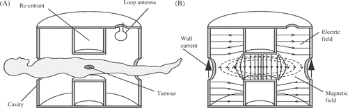
We have studied the cavity-based heating applicator described by Ishihara and colleagues Citation[14–17]. In the rectangular cavity resonator shown in , for example, the electric field distribution is generated as a standing wave in the vertical direction of the cavity resonator, and the field strength at the resonator's centre reaches a maximum with the lowest resonant mode. Localised heating can be obtained by using this electric field distribution as a heat source. In addition, superior localised heating characteristics are obtained Citation[14–17], especially in our proposed re-entrant cavity resonator, since the electric field distribution is that shown in . Thus, by placing a region of the human body between the re-entrant electrodes for treatment, a deep lesion in the body can be heated locally, non-invasively, and without contact.
Figure 1. Electromagnetic distribution of the lowest (TE101) mode in a rectangular cavity resonator.
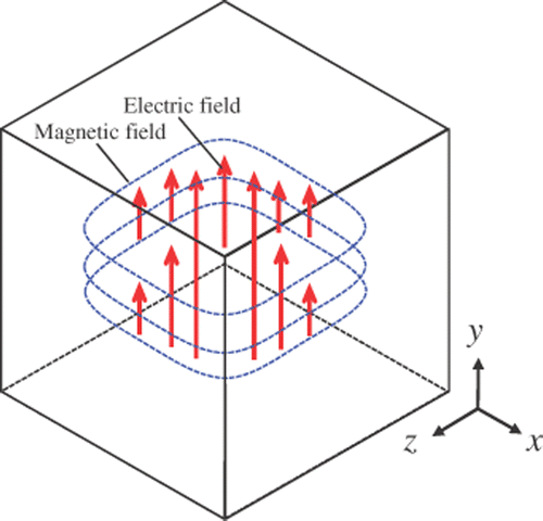
Figure 2. Cross section of applicator and electromagnetic field distribution of the lowest (TM010) mode in a re-entrant cavity resonator.
Even if non-invasive heating can be achieved by these methods, a temperature probe would need to be inserted into the heating target region to measure the temperature change. In this study, therefore, we considered the temperature dependence of the dielectric constant. For example, the temperature dependence of the dielectric constant of pure water is given by Equation 1 Citation[18] and allows the resonant frequency change due to the change in dielectric constant ε with temperature to be detected.T represents the temperature (°C). It is well known in the field of material analysis that the dielectric constant of a target material can be measured from the resonant frequency of a cavity resonator by using changes in the dielectric constant Citation[19], Citation[20]. The temperature dependence of the dielectric constant for some materials can then be estimated by observing the resonant frequency change with temperature using the same principle. However, since it is necessary to measure a frequency change of only tens of kilohertz, in contrast to a resonant frequency of hundreds of megahertz, this measurement is particularly difficult when a living body is the target. In such cases, the frequency change with temperature cannot be measured directly; furthermore, the spatial frequency change (distribution) cannot be distinguished.
Thus, we focus on the fact that a phase change due to a frequency change may be detected, which improves the measurement accuracy and provides spatial information. As expressed in Equation 2, the minute frequency change with temperature can be detected as an expanded phase change in the electromagnetic waves (i.e. Δθ) by adjusting the observation time. (It corresponds principally to a delay time with respect to a certain reference time.)T0, r, and tdelay represent the reference temperature (°C), spatial vector, and time delays with respect to a reference time (s), respectively. Accordingly, we expect that the dynamic range of the detectable temperature change can be improved.
CT algorithm
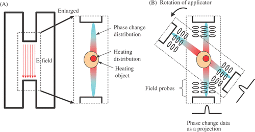
Electromagnetic waves can be observed only outside the target body. Therefore, it is necessary to estimate the phase change distribution inside a target body and convert the phase change to a temperature change. An example is illustrated in . The phase change distribution of the electromagnetic waves formed in the cavity resonator is distributed mainly in the direction parallel to the electric field Citation[12], which will be shown later. In this case, the projection data reflecting the line integral value of the phase change distribution along the electric field are similar to those showing X-ray absorption in the case of X-ray CT. Therefore, we believe that the phase distribution within an object can be estimated by rotating the cavity resonator, as shown in , as in the case of that obtained in an object with X-ray CT. We demonstrate that a CT algorithm based on a back-projection method could be applied by considering the characteristics of the electromagnetic field formed in a cavity resonator and the temperature dependence of the dielectrics in an object.
Figure 3. CT algorithm. Phase change distribution before and after a temperature change in a heating applicator (re-entrant cavity resonator) (A) is acquired as projection data at each rotational angle (B).
Methods
Experimental system
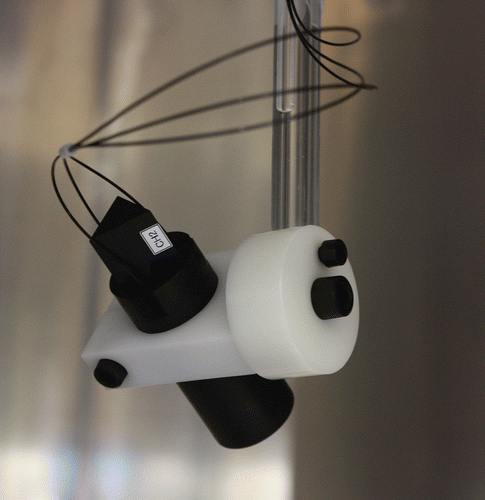
To evaluate the efficiency of the proposed method and the results of computational analysis Citation[12], we built a prototype system based on a rectangular cavity resonator. A configuration diagram of this system is shown in , and an outline drawing and photograph are provided in . The cavity resonator is a 1.0 m aluminum cube with a resonator frequency of about 212 MHz; it can be rotated 360° about the z-axis (). Its internal structure is shown schematically in . To make measurements without disturbing the electromagnetic field distribution, we used an optical electric field sensor head (OEFS-NS; Seikoh Giken, Matsudo, Chiba, Japan). The phantom installation table and a fixture for the sensor are made of acrylic, and part of the axis of rotation is made of Teflon (). Since the antenna electrode inside the sensor was arranged along three axes, the sensor can measure three components of the electric field distribution.
Figure 4. Configuration diagram of prototype temperature measurement system.
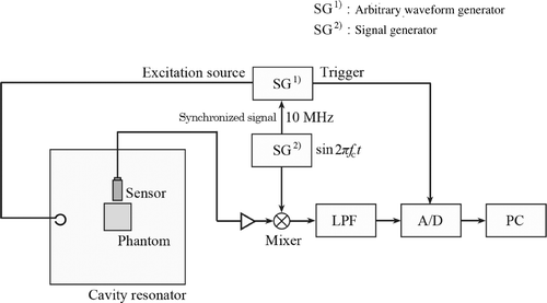
Figure 5. Overview of prototype system. Third angle projection of rectangular cavity resonator (A). External view of entire system (B).
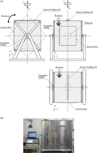
Figure 6. Internal structure of rectangular cavity resonator.
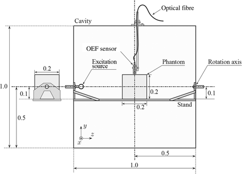
Figure 7. Optical electric sensor head held by a Teflon fixture.
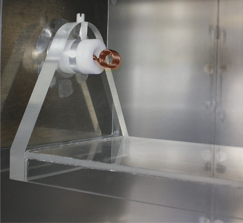
To excite the cavity resonator, a loop antenna with five turns was installed, as shown in , and excitation waves were supplied by an arbitrary waveform generator (SG1, E4430B; Agilent Technologies, Santa Clara, CA). It was difficult to perform direct analogue-to-digital (AD) translation of measured electromagnetic wave data at high frequency (about 200 MHz). Therefore, the data were subsequently converted to an intermediate frequency of 10 MHz by using signal generator SG2 (AFG3252; Tektronix, Beaverton, OR), which satisfied the sampling condition of an AD converter (M2i4031; Mish, Tokyo, Japan). The down-converted data were loaded into a personal computer (dc7800 MT/CT; Hewlett-Packard, Palo Alto, CA). Here, to ensure the synchronisation of the two signal generators, SG1 and SG2, the reference synchronising signal of SG2 was supplied to SG1 for an excitation source output.
Figure 8. Fixed table made from acrylic to hold the phantom.
Phantom model
Ideally, the projection data for image reconstruction should be measured for various temperatures of the phantom placed inside a cavity resonator, and the proposed image reconstruction method should be evaluated. However, in this experiment, the difference in the dielectric constants of two phantoms (water and glycerine) was used to simulate a temperature change. Each liquid substance was enclosed in an acrylic case consisting of a 0.1 m cube placed at the centre of the cavity resonator (). Here, the phantom temperature during a measurement period was maintained at a constant 22°C (the dielectric constants of water and glycerine are 79.3 and 42.8, respectively, at this temperature).
Excitation waveform
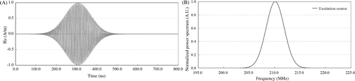
To form the standing wave mode of the cavity resonator shown in , it was necessary to excite the resonator with the resonant frequency corresponding to the standing wave mode. At the same time, it was necessary to cut off the electromagnetic field components of other resonance modes of the resonator. An excitation wave has to include frequency components that cover the range of frequency changes accompanying temperature change Citation[12]. Therefore, after the resonant frequency was measured using a spectrum analyser (E4402B; Agilent) when the water and glycerine phantoms were inserted separately into the resonator, the average of both resonant frequencies (pure water: 210.05 MHz, glycerine: 210.13 MHz) was set as the central frequency f0 of the excitation source. A time series waveform that covered this frequency band was chosen as the excitation source Hx ().
Figure 9. Excitation waveform for cavity resonator. Gaussian waveform modulated by resonant frequency (A). Frequency component of this time waveform (B).
Electromagnetic wave measurement and image reconstruction
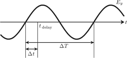
After each phantom was inserted into the cavity resonator, the optical electric field sensor was arranged in a position about 0.01 m (y = 0.61 m) from the upper part of the phantom's surface. The sensor was then scanned in steps of 0.025 m from 0.25 m to 0.75 m along the x direction, and time series electric field data with a y-direction component were measured at a total of 21 points (). The phase change corresponding to Equation 2 was computed on the basis of from the obtained electromagnetic waves. Next, the phase change was computed by Equation 3 using the time difference (Δt) on the basis of the delay time (tdelay) and the period of electromagnetic waves (ΔT) observed around tdelay.
Figure 10. Set-up of phantom and collection range of projection data in cavity resonator.
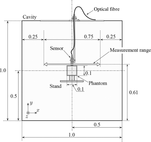
Figure 11. Definition for calculating the phase information at a given delay time.
An image of the phase change distribution was reconstructed using these phase changes as projection data in a simple back-projection method Citation[13].
Results
Measured electromagnetic waves and projection data
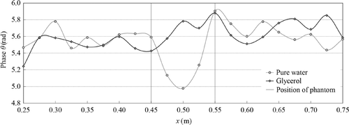
Examples of the y component of electromagnetic waves for each phantom are shown in . Each figure includes the time series data per 1 µs at the measuring positions x = 0.3, 0.4, and 0.5 m (10 000 signals are averaged for each data point). The phase distribution of the x component of the electromagnetic waves for each phantom at a delay time of 400 ns is shown in . Here, although the results of numerical analysis Citation[12] and later discussion (see ) showed that the phase change was most clearly detected with high sensitivity at a delay time of around 200 ns, the delay time was set to 400 ns, since (1) the signal intensity was small at a delay time of about 200 ns, especially for glycerine, as shown in , and (2) a resonator would be in a completely resonant condition when the delay time is considerably greater than 400 ns. shows that the phase value at the phantom's position (around x = 0.5 m) became smaller than that at the other positions (x = 0.250–0.425 m and 0.575–0.750 m).
Figure 12. Waveform of electric field measured using optical electric field sensor at each position. The sensor was moved in the x (axial) direction near the centre of the cavity resonator, as shown in (x = 0.25–0.75 m). Time series waveform of y component of electric field for pure water (A). Time series waveform of y component of electric field for glycerine (B).
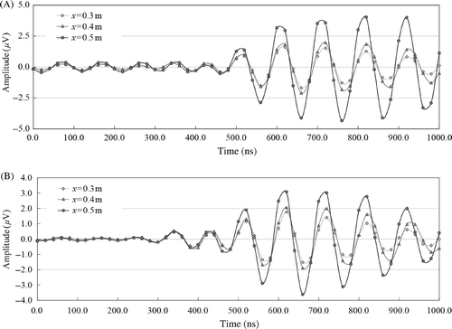
Figure 13. Phase distribution of electromagnetic waves for each phantom.
shows the projection data computed from both phantoms’ phase differences, which became large around the phantom's position due to the difference between the phantoms’ dielectric constants. Therefore, this indicated that a temperature change (represented here by the change in dielectric constant) could be detected using the phase information for the y component of a standing wave in the cavity resonator.
Figure 14. Phase difference with the dielectric constant change, which simulated a temperature change, as projection data.
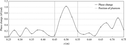
However, a relatively large error (0.64 rad) around the periphery and an average error of 0.21 rad were observed. The cause of these errors and their effect on image reconstruction are considered later.
Image reconstruction
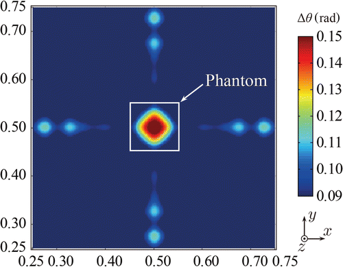
The phase change distribution reconstructed with a simple back-projection CT algorithm is shown in . Here, since the cubic phantom was arranged at the centre of the resonator and the projection data at rotation angles of 0°, 90°, 180°, and 270° became the same, a phase change profile observed from the 0° direction () was used to represent projection data observed from all four directions. The x-direction phase change profile of the reconstructed image then showed the same distribution as the projection data, confirming that reconstruction by back projection was performed correctly. Therefore, we confirmed that the phantom position, which corresponds to the region in which the dielectric constant changes, can be imaged, although the area surrounding the reconstructed phase change distribution was blurred because of the point spread function of simple back projection, as anticipated.
Figure 15. Phase change image reconstructed from 4-projection data by simple back projection.
Discussion
We experimentally confirmed the ability to detect a temperature change in an object in a cavity resonator by observing phase changes in electromagnetic waves resulting from a change in the dielectric constant associated with a temperature change. The difference in the dielectric constants of water and glycerine, which were used in this experiment, is equivalent to a temperature difference of about 130°C in a biological fluid. However, when the numerical analysis by the FDTD method Citation[12] was applied under the experimental conditions, the numerical analysis and experimental results agreed, with an error of about 22% (the phase detection sensitivities of the numerical analysis and experiment were 0.0016 rad/°C and 0.0020 rad/°C, respectively). Although the size of the temperature change region and the heterogeneity of the dielectric constant distribution must be examined in the future, we demonstrated that a temperature change of a few degrees Celsius might be detectable by this method as it is by the numerical analysis. The experimental error is related to the detection accuracy of phase changes observed mainly as projection data. Some factors that affect the detection accuracy of the projection data are discussed below.
Delay time for phase change measurement
Although it is generally well known that a change in dielectric constant can be estimated from a resonant frequency change in an entire cavity resonator (i.e. the averaged resonant frequency) Citation[19], Citation[20], the proposed method estimates the dielectric constant at each point from the phase change distribution due to the frequency change with temperature. Note that in time, the electromagnetic waves in a cavity resonator eventually reach the constant resonant frequency derived from the size of the resonator and the features of its internal material. That is, although the accumulated phase change at each point is proportional to the delay time tdelay, as shown in Equation 2, the phase change after a certain time is expected to become ‘in-phase’ at every point because the standing wave is formed in a cavity. Therefore, to detect changes in the dielectric constant with temperature using the distribution of the phase change at each point, an appropriate delay time must be chosen.
shows the results of a numerical analysis that evaluated the phase difference between the inside and outside of a phantom placed at the centre of a cavity resonator against the delay time. The phase difference was greatest around a delay time of 200 to 250 ns, so it is advantageous to acquire the phase change data using this delay time to optimise the phase detection sensitivity. (The discontinuous phase change immediately after an excitation pulse (delay time <50 ns) is considered to indicate phase wrapping resulting from an insufficient signal amplitude for calculating an accurate phase value.) However, in this experiment, since the amplitude of the electromagnetic waves around a delay time of 200 ns was small (), it was necessary to acquire data at a delay time of about 400 ns. Since the resonator approaches the resonant condition during this longer delay time, as mentioned above, the phase change detection sensitivity is expected to have deteriorated.
Figure 16. Numerical analysis results Citation[12] showing detection sensitivity of phase changes in a rectangular cavity resonator.
![Figure 16. Numerical analysis results Citation[12] showing detection sensitivity of phase changes in a rectangular cavity resonator.](/cms/asset/e8b6df5b-2906-4bb9-b2c9-638006a1b8b1/ihyt_a_602038_f0016_b.gif)
Excitation power of cavity resonator
Limitations in the signal detection sensitivity cause an image artefact in the circumference of the reconstructed image, as shown in . This is also indicated in the projection data shown in , and a large error in the phase difference is observed in the area corresponding to the circumference of the phantom. In this experiment, since the output of SG1 (13 dBm) was directly connected to the coil to excite the resonator, high-frequency power may not be transmitted efficiently. The reconstruction accuracy is likely to be improved by accurate impedance matching and amplification of the transmitted electromagnetic power (the current return loss is about 10 dB), since it is possible to increase the amplitude of the electromagnetic waves in a cavity resonator.
Sensitivity of optical electric field sensor
The antenna elements of the optical electric field sensor used for this experiment are 2 cm in length. The sensitivity could also be improved by lengthening these elements. However, since it is difficult to achieve a good balance between high spatial resolution and accuracy of the reconstructed image owing to the inverse relationship between detection sensitivity and antenna length, it is realistic to improve the measurement sensitivity by increasing the intensity of the excitation source as described above.
On the other hand, measurement using the average of 10 000 signals is required because of the inadequate signal intensity, and the measurement time corresponds to roughly several minutes. By increasing the high-frequency power output from an excitation coil as mentioned above, the time resolution can also be improved significantly. Conducting simultaneous measurements using multiple and/or parallel electric field sensors is expected to improve the time resolution considerably.
In this experiment, as described above, errors and artefacts (noise components) appeared in the reconstructed image because of limited signal detection sensitivity, and some differences from the results of numerical analysis were observed. Furthermore, since few points were sampled owing to constraints on the size of the optical electric field sensor, and few projection directions were used, the reconstructed image indicated an intensity peak at the centre. However, because an earlier numerical analysis Citation[12] indicates that the distribution that reflects a temperature change can be reconstructed by increasing the number of data points, we think that the same result would also be obtained in an experiment that uses the proposed method if the problem of the signal detection sensitivity described above were solved. To establish this method, the following issues should be addressed in addition to the signal detection sensitivity.
Coefficient of conversion from phase change to temperature change
To estimate the temperature change distributions and evaluate the reconstruction accuracy, we must convert phase change distributions associated with temperature changes into straightforward temperature changes. Since the reconstructed phase change depends on (1) the dielectric constant of an object, (2) the temperature dependence of the dielectric constant, (3) the delay time, (4) the integration range for creating projection data, and (5) the shape of the reconstruction filter, it is difficult to determine a conversion coefficient using only the measured phase change distribution. Although it is possible to use the reconstructed result when a uniform temperature change in a phantom is given as calibration data, a large error may result from differences in the resonant conditions when different objects are inserted in the resonator. Therefore, a more realistic and effective calibration method for the proposed technique is to measure the temperature of an object's surface with a fibre-optic thermometer and use the result as calibration data.
Measurement time resolution
We mentioned above that the signal detection sensitivity imposes a large constraint on the time resolution. In addition, it is necessary to obtain the projection data from all directions in this thermometry method. Therefore, reconstruction errors will occur if the temperature changes during the acquisition of projection data. Although the temperature change in hyperthermia is gradual, the time resolution may be insufficient for heating control. In this case, the time resolution can be improved by acquiring projection data at a decimated projection angle.
Temperature dependence of the dielectric constant
Since the temperature dependence of the dielectric constant is expected to differ according to the tissue type Citation[21–23], for clinical application it will be necessary to investigate the reconstruction of the temperature change distribution using a biological tissue model and to evaluate the measurement error generated in the required temperature range. However, because the range of temperature change in hyperthermia is relatively narrow (about 5°C) as compared to focused ultrasound surgery (FUS) Citation[24], differences in the temperature dependence may not be a serious problem.
Conclusions
We performed experiments to examine our proposed method of non-invasive thermometry using phase changes in electromagnetic waves in a cavity resonator. The experimentally observed phase change differed somewhat from the results of numerical analysis, mainly because of the limited detection sensitivity for electromagnetic waves. However, our experimental results indicated that a temperature change inside an object could be detected by observing the phase change distribution accompanying the associated dielectric constant change in a cavity resonator. The proposed method can be easily embedded in a heating applicator based on a cavity, so a novel cancer treatment system that combines localised heating of cancers with non-invasive temperature monitoring could be established.
Declaration of interest: This study was supported by the Industrial Technology Research Grant Program 2006 from the New Energy and Industrial Technology Development Organization (NEDO) of Japan and a Grant-in-Aid for Scientific Research (B), 20300155, 2008 from the Japan Society for the Promotion of Science (JSPS). The authors alone are responsible for the content and writing of the paper.
References
- Perez CA, Gillespie B, Pajak T, Emami NB, Rubin P. Quality assurance problems in clinical hyperthermia and their impact on therapeutic outcome: A report by the radiation therapy oncology group. Int J Radiat Oncol Biol Phys 1989; 16: 551–558
- Perez CA, Pajak T, Emami B, Hornback NB, Tupchong L, Rubin P. Randomized phase III study comparing irradiation and hyperthermia with irradiation alone in superficial measurable tumors. Final report by the radiation therapy oncology group. Am J Clin Oncol 1991; 14: 133–141
- Cetas CT. Will thermometric tomography become practical for hyperthermia treatment monitoring?. Cancer Res 1984; 44: 4805s–4808s
- Ishihara Y, Calderon A, Watanabe H, Mori K, Okamoto K, Suzuki Y, Sato K, Kuroda K, Nakagawa N, Tsutsumi S, A precise and fast temperature mapping using water proton chemical shift. Proceedings of the Society of Magnetic Resonance in Medicine, 11th Annual Meeting, Berlin, Germany, 1992, p. 4804
- Ishihara Y, Calderon A, Watanabe H, Okamoto K, Suzuki Y, Kuroda K, Suzuki Y. A precise and fast temperature mapping using water proton chemical shift. Magn Reson Med 1995; 34: 814–823
- McDannold N, Tempany CM, Fennessy FM, So MM, Rybicki FJ, Stewart EA, Jolesz FA, Hynynen K. Uterine leiomyomas: MR imaging-based thermometry and thermal dosimetry during focused ultrasound thermal ablation. Radiology 2006; 240: 263–272
- Gellermann J, Wlodarczyk W, Hildebrandt B, Ganter H, Nicolau A, Rau B, Tilly W, Fähling H, Nadobny J, Felix R, Wust P. Noninvasive magnetic resonance thermography of recurrent rectal carcinoma in a 1.5 tesla hybrid system. Cancer Res 2005; 63: 5872–5880
- Prionas SD, Hahn GM. Noninvasive thermometry using multiple-frequency-band radiometry: A feasibility study. Bioelectromagnetics 1985; 6: 391–404
- Miyakawa M. Tomographic measurement of temperature change in phantoms of the human body by chirp radar-type microwave computed tomography. Med Biol Eng Comput 1993; 31: S31–S36
- Ishihara Y, Endo Y, Wadamori N, Ohwada H, A noninvasive temperature measurement regarding the heating applicator based on a reentrant cavity. Proceedings of 2007 Joint Annual Meeting of the World Conference on Interventional. Oncology (WCIO) and the Society for Thermal Medicine (STM), Washington, DC, 2007, pp. 232–233
- Ishihara Y, Endo Y, Ohwada H, Wadamori N, Noninvasive thermometry in a reentrant resonant cavity applicator, Proceedings of the IEEE of the 29th Annual International Conference of the Engineering in Medicine and Biology Society, 2007, Lyon, France, 2007, pp. 1487–1490
- Ohwada H, Ishihara Y. A fundamental numerical analysis for noninvasive thermometry integrated in a heating applicator based on the reentrant cavity. Thermal Med 2010; 26: 51–62
- Kak AC, Slaney M. Principles of Computerized Tomographic Imaging. IEEE Press, New York 1988
- Ishihara Y, Gotanda Y, Wadamori N, Matsuda J. Hyperthermia applicator based on reentrant cavity for localized head and neck tumors. Rev Sci Inst 2007; 72: 024301.1–024301.8
- Ishihara Y, Wadamori N. Heating applicator based on reentrant cavity with optimized local heating characteristics. Int J Hyperthermia 2008; 24: 694–704
- Ishihara Y, Kameyama Y, Wadamori N, Localized heating method by a rotatable applicator based on a reentrant cylindrical cavity. Proceedings of the Society for Thermal Medicine Annual Meeting, Tucson, AZ, USA, 2009, p. 172
- Ishihara Y, Kameyama Y, Ino Y, Wadamori N. Improvement in localized heating characteristics by loading dielectrics in a heating applicator based on a cylindrical reentrant cavity. Thermal Med 2008; 24: 61–72
- Buckley F, Maryott AA. Tables of dielectric dispersion data for pure liquids and dilute solutions. Natl Bur Stand Circ 1958; 589: 1–6
- Pointon AJ, Woodman KF. A coaxial cavity for measuring the dielectric properties of high permittivity materials. J Phys E: Sci Instrum 1971; 4: 208–210
- Karikh NM. Method of calculating dielectric permittivity in a partly filled resonator cavity. Meas Tech 1977; 20: 68–71
- Chou CK, Chen GW, Guy AW, Luk KH. Formulas for preparing phantom muscle tissue at various radiofrequencies. Bioelectromagnetics 1984; 5: 435–441
- Fukunaga K, Watanabe S, Yamanaka Y. Dielectric properties of tissue-equivalent liquids and their effects on specific absorption rate. IEEE Trans Electromagn Compat 2004; 46: 126–129
- Lazebnik M, Converse MC, Booske JH, Hagness SC. Ultrawideband temperature-dependent dielectric properties of animal liver tissue in the microwave frequency range. Phys Med Biol 2006; 51: 1941–1955
- Botnar RM, Steiner P, Dubno B, Erhart P, von Schulthess GK, Debatin JF. Temperature quantification using the proton frequency shift technique: In vitro and in vivo validation in an open 0.5 tesla interventional MR scanner during RF ablation. J Magn Reson Imaging 2001; 13: 437–444