Abstract
Purpose: This paper outlines a theoretical approach for optimisation of the coagulation zone for thermal ablation procedures and considerations for its practical application. Methods: The theoretical approach is outlined in the Cartesian coordinate system. Considerations for practical application are implemented. The optimised coagulation zone is defined as the bare coverage of tumour mass plus a safety margin. The eccentricity of coagulation centre (ECC) is defined as the distance between the coagulation centre and the tumour centre. The direction of the applicator shaft is determined based on the x-axis direction. The tumour centre and coagulation centre are defined within the x/y-plane. The distance between coagulation margin (applicator tip) and tumour margin is called parallel offset (PAO). Results: For spherical coagulation shapes, a linear relationship exists between optimised coagulation diameter and ECC. An exponential relationship exists between optimised coagulation volume and ECC. A complex relationship was found between PAO and determinants of ECC, which are ex and ey. PAO is an extremely important parameter, which allows for determination of the optimal applicator tip position in relation to the tumour margin. It can be calculated in such a manner that the optimised coagulation zone is minimised by neutralising dislocation of the coagulation centre in applicator shaft direction. The latter can be realised by withdrawing or further inserting the applicator shaft. Conclusions: The presented concept can be used to optimise the extent of the coagulation zone for thermal ablation procedures after positioning of the applicator. Its inherent advantage is the simple adjustment of the applicator shaft, which obviates the need for a repuncture.
Introduction
Thermal ablation constitutes a procedure which was established for the treatment of lung, bone, liver and kidney tumours [Citation1]. Radiofrequency ablation and microwave ablation are also commonly used to create tissue necrosis at temperatures beyond 70 °C [Citation2,Citation3]. Cryoablation, however, destroys parenchymal structures at temperatures below −70 °C [Citation2,Citation4]. Basically, thermal ablation can be classified as needle-based techniques with an applicator introduced into the tumour [Citation4].
The position of the applicator in relation to the tumour plays a major role when it comes to ensuring the coagulation zone’s complete coverage of the tumour mass. Tumour size, safety margin, distance of the applicator shaft to the tumour centre and position of the applicator tip in relation to the tumour margin are all parameters that have to be considered. Complexity further increases with the broad spectrum of commercially available thermal ablation systems [Citation5]. Muller et al. published a detailed proposal for the standard description of the coagulation zone [Citation6]. This proposal defines the coagulation zone’s long and short diameter, front margin, coagulation centre and ellipticity index as important measures. Although these parameters vary between different systems, modern thermal ablation devices can create rather symmetrical and ellipsoid coagulation zones [Citation7–9]. Detailed geometrical knowledge of the relationship between applicator position and tumour size is therefore important when it comes to the selection of the appropriate ablation parameters (e.g. power output and ablation time). The resulting coagulation zone is optimal when it is sufficiently large to completely destroy the tumour and is small enough to spare viable anatomical structures. To date, we could not identify any publications describing a systematic approach in dealing with such geometrical relationships, neither theoretically nor practically.
Thermal ablation can provide high rates of oncological success in a selected group of patients (e.g. T1a renal cell carcinoma) [Citation10]. This may be due to the fact that experienced operators achieve optimal applicator positioning and accurately choose the most suitable ablation parameters. The published works dealing with the optimisation of thermal ablation (e.g. image fusion and thermal modelling) help to further improve the procedural outcome [Citation11,Citation12]. Our concept may serve as an additional tool in the armamentarium of optimised thermal ablation to correct and minimise errors in the placement of the applicator.
In the first part of the paper we describe a theoretical approach with spherical coagulation shapes. Spherical coagulation shapes are relevant as they define the perfect coagulation zone for spherical tumours. For reasons of simplification, tumour shapes are always assumed to be spherical in this manuscript since 1) the majority of tumours accessible to routine thermal ablation can be regarded as spherical (e.g. T1a renal cell carcinoma or Barcelona Clinic Liver Cancer stage A hepatocellular carcinoma) and 2) the entrance angle between the applicator shaft and a spherical tumour is irrelevant (which is not the case for non-spherical tumours) [Citation10,Citation13]. Spherical coagulation shapes allow calculation of the absolute minimum radius, diameter and volume of the coagulation zone necessary to barely cover tumour plus safety margin at a specific applicator position. In Part 2 of the paper we describe an approach with ellipsoid coagulation shapes. For the clinical routine, ellipsoid coagulation shapes are more relevant, but suffer the disadvantage of unnecessary tissue destruction when compared with spherical coagulation shapes. In both parts, considerations for practical use are implemented. Additionally, we demonstrate how the presented concept may be applied to optimise the coagulation zone after positioning of the applicator and without the need for repuncture.
Materials and methods
The work described herein is a theoretical approach with considerations for practical use to optimise the coagulation zone for thermal ablation procedures performed with a single straight needle applicator. The theoretical approach takes place in the Cartesian coordinate system. The considerations for practical use are demonstrated using a computerised tomography (CT) system with 3D image post-processing. After local ethics committee approval, the liver of a sheep was imaged during CT-guided positioning of a 14-gauge straight needle applicator for microwave ablation (Amica, HS Hospital Service, Rome, Italy). The optimised coagulation zone is defined as the coagulation zone (spherical in Part 1 and ellipsoid in Part 2) that barely covers the tumour and includes a safety margin. To create a scenario as realistic as possible, concrete quantitative data (coagulation short and long diameter, ellipticity index and coagulation centre) are used from the commercial information of a microwave ablation system (Amica) for ellipsoids in Part 2. Parameters to be considered are tumour size, safety margin and eccentricity of the coagulation centre (ECC). ECC is defined as the distance between the coagulation centre and the tumour centre (see below).
Part 1: Spherical coagulation shapes
Specific definitions
The tumour is defined as a tumour sphere with a diameter (dt) and a radius (rt):
The tumour volume (Vt) is defined as
In the Cartesian coordinate system the centre of the tumour sphere (T) is defined as the coordinate T (0, 0, 0). The safety margin sphere features the same centre as the tumour sphere, but radius (rc*), diameter (dc*) and volume (Vc*) are dependent on tumour radius and safety margin (s) ():
and
and
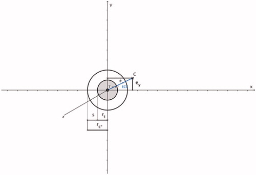
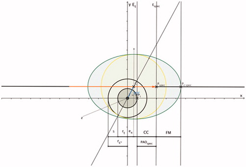
Figure 1. Tumour sphere (shaded grey; tumour centre T and tumour radius rt), safety margin sphere (non-shaded; safety margin s, centre C* (= T) and radius rc*) and coagulation centre C with ECC (marked as blue line); rc* = rt + s and ECC = √(). Since the tumour centre and coagulation centre are always defined in the x/y-plane, the coagulation centre always has the coordinate C (ex, ey, 0).
The safety margin sphere is identical to the perfect coagulation zone. The optimised coagulation zone is defined as a coagulation sphere with an optimised coagulation diameter (dc) and an optimised coagulation radius (rc):
The optimised coagulation volume (Vc) is defined as
It is extremely important to emphasise that in the Cartesian coordinate system, the direction of the applicator shaft is always defined in the x-axis direction. In contrast, tumour centre and coagulation centre are always defined in the x/y-plane (). This scenario can be implemented in the clinical workflow within the context of CT-guided thermal ablations by using 3D image post-processing. The proper positioning of the applicator within the liver was achieved by using standard image planes (). In the standard image planes, the entire course of the applicator shaft, as well as a fictive tumour centre, did not present in one single image slice. Therefore, the distance between the applicator shaft and the (fictive) tumour centre could not be determined. Individual image angulation took place in such a manner that conditions identical with the Cartesian coordinate system existed: the entire course of the applicator shaft, as well as, the fictive tumour centre then figured in one single image slice (master image slice). The master image slice included the x-axis and y-axis as in the Cartesian coordinate system. The direction of the x-axis was defined by the direction of the applicator shaft, and the y-axis was defined as being perpendicular to the applicator shaft. In the master image slice, the distance between the applicator shaft and the tumour centre could be defined.
Figure 2. Spherical coagulation zone (shaded in yellow; coagulation centre C), coagulation radius rc and applicator (marked in red). The direction of the applicator shaft (marked as a red line) is always defined in the x-axis direction; the applicator shaft crosses the coagulation centre C and the applicator tip (marked as a red arrowhead) ends at the surface point Pc on the coagulation margin; the coagulation centre is always defined in the x/y-plane.
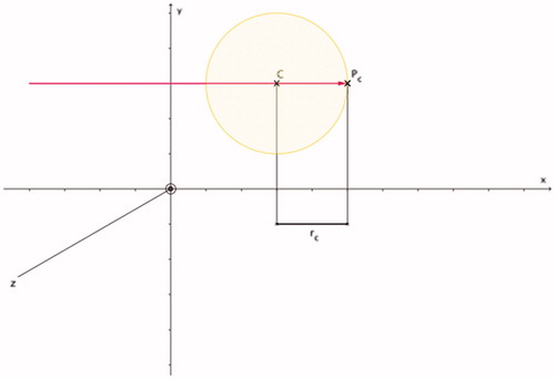
Figure 3. Coagulation radius rc of the optimised coagulation zone (shaded in yellow; coagulation centre C) can be calculated: rc = ECC + rt + s. Based on and .
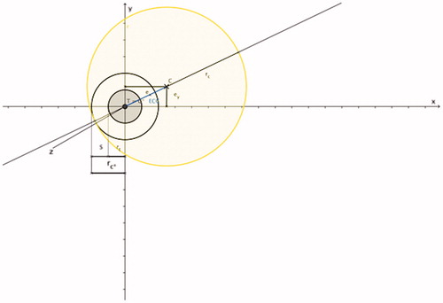
Figure 4. PAO indicates the radial distance in x-axis direction (applicator shaft direction) between surface point Pc on the coagulation margin and surface point Pt on the tumour margin: PAO = ECC + ex + s. Based on , and ; PAO is the radial distance between two work planes (work plane Et perpendicular to the x-axis intersecting surface point Pt and work plane Ec perpendicular to the x-axis intersecting surface point Pc).
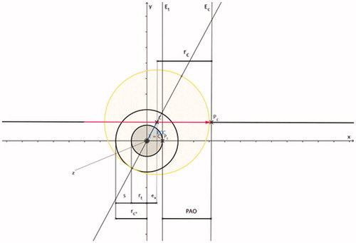
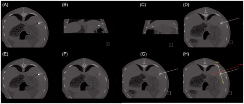
Figure 5. Feasibility of CT-guided thermal ablation by using 3D image post-processing with definition of the master image slice. (A–C, E, F) Standard image planes (transversal, coronal and sagittal). (D, G, H) Master image slice. Positioning of the applicator using standard image planes (A–C). In the standard image planes, the entire course of the applicator shaft (A, E), as well as a fictive tumour centre (white X) (F) did not appear in one single image slice. After individual image angulation the entire course of the applicator shaft as well as the fictive tumour centre (white X) became obvious in one single image slice (master image slice) (D, G, H) with x-axis and y-axis as defined in the Cartesian coordinate system. The direction of the x-axis (red) defined the direction of the applicator shaft; the y-axis (yellow) was defined as being perpendicular to the applicator shaft. In the master image slice, the distance between the applicator shaft and the tumour centre (white X) defines ey (green) (H).
In the Cartesian coordinate system, the coagulation centre (C) was labelled with the coordinate C (ex, ey, 0). It was also assumed that 1) the applicator shaft crosses the coagulation centre and 2) the applicator tip ends at the coagulation margin (surface point Pc) (). That way the optimised coagulation zone barely covered the safety margin sphere (). ECC is defined as the distance between the coagulation centre and the tumour centre, and can be calculated ( and ) as
The optimised coagulation radius (rc), the optimised coagulation diameter (dc), as well as the optimised coagulation volume can all be calculated ( and ) as
and
and
The distance between the coagulation margin (applicator tip) and the tumour margin is defined as the parallel offset (PAO) (). PAO, in turn, can be calculated as the radial distance in x-axis direction (applicator shaft direction) between the surface point Pc on the coagulation margin and the surface point Pt on the tumour margin:
Applying Equations 8, 9 and 12, PAO can also be calculated as follows:
Since Pc is identical to the applicator tip (), PAO signifies the distance between the applicator tip and the tumour margin in the applicator shaft direction. During CT-guided clinical thermal ablation, all parameters of Equations 1–12 can be determined by using the master image slice ().
Examples
Based on spherical coagulation shapes (as the perfect coagulation zone with absolute minimum radius, diameter and volume), the following study goals were defined.
To demonstrate the impact of ECC on the optimised coagulation zone.
To demonstrate the importance and practical value of PAO, especially how it can be used in the optimisation of the coagulation zone after the applicator is already positioned and thereby avoiding the need for repuncture.
To illustrate the above-mentioned relationships, concrete examples featuring different tumour sizes (dt = 1.0 cm and 3.0 cm) and ECCs (ex and/or ey = 0 cm, 0.5 cm and 2.0 cm) are outlined. The safety margin is always defined as s = 0.5 cm, which corresponds with a recently published study [Citation14,Citation15]. The optimised coagulation zone for spherical coagulation shapes is achieved by determining optimised values for the coagulation radius, diameter, and volume. Corresponding PAOs are listed for all cases.
Part 2: Ellipsoid coagulation shapes
Specific definitions
To increase the application’s clinical relevance for interventional oncologists, coagulation shapes that are more common in the clinical setting are implemented based on fundamental findings of Part 1 above. As published previously, the most common coagulation shapes for thermal ablation with single straight needle applicators are ellipsoids. With ellipsoids, the coagulation long diameter (CLD) follows the applicator shaft direction, and the coagulation short diameter (CSD) runs perpendicular to the applicator shaft direction [Citation6,Citation7,Citation15,Citation16]. The ratio of the coagulation short diameter and the coagulation long diameter is defined as the ellipticity index (EI) [Citation6,Citation16]. The coagulation centre (CC) is defined as the distance between the projection of the site of the coagulation short diameter on the applicator shaft and the applicator tip [Citation6]. Another descriptive measure is the front margin, which was determined to be the distance between the distal edge of the coagulation zone and the applicator tip [Citation6]. Contrary to spherical coagulation shapes, the tip of the applicator does not end at the coagulation margin (surface point Pc_spec) (). The optimised coagulation short diameter for ellipsoid coagulation shapes is identical to the optimised coagulation diameter for spherical coagulation shapes. Applying the ellipticity index, the coagulation long diameter can be calculated:
Figure 6. PAOspec indicates the radial distance in x-axis direction (applicator shaft direction) between the applicator tip (Pspec) and the surface point Pt on the tumour margin: PAOspec = CC + ex – rt.Based on ; ellipsoid coagulation zone (shaded in green; applicator (marked in orange); PAOspec is the radial distance between two work planes (work plane Et is perpendicular to the x-axis and intersects with surface point Pt and work plane Espec is perpendicular to the x-axis and intersects with surface point Pspec); CC is the distance between the projection of the site of the coagulation short diameter on the applicator shaft (C) and the applicator tip (Pspec); the front margin (FM) is the distance between the distal edge of the coagulation zone (Pc_spec) and the applicator tip (Pspec).
The optimised coagulation volume for ellipsoid coagulation shapes (Vc_spec) is defined as [Citation17]
By applying the coagulation centre (CC), the specific PArallel Offset (PAOspec) () is defined as
Examples
Based on ellipsoid coagulation zones (as they are more clinically relevant, but with the disadvantage of unnecessary tissue destruction when compared with spherical coagulation shapes), the following study goals are defined.
To demonstrate the impact of ECC on the optimised coagulation zone
To demonstrate the importance and practical value of PAOspec, especially, how it can be used in the optimisation of the coagulation zone after the applicator is already positioned and without needing to repuncture.
Thereby, differences compared with spherical coagulation shapes are demonstrated. To illustrate the abovementioned relationships, concrete examples with different tumour sizes (dt = 1.0 cm and 3.0 cm) and ECCs (ex and/or ey = 0 cm, 0.5 cm and 2.0 cm) are listed. The safety margin is always defined as s = 0.5 cm [Citation15]. The optimised coagulation zone for ellipsoid coagulation shapes is achieved by optimising the following parameters: coagulation short diameter, ellipticity index, coagulation long diameter, optimised coagulation volume, and coagulation centre. Corresponding PAOsspec are listed for all cases.
Results
Part 1: spherical coagulation shapes
Specific definitions
Diameter and volume of the optimised coagulation zone are considered perfect when 1) the coagulation centre is identical with the tumour centre, which means that ECC = 0, and 2) the coagulation sphere is identical with the safety margin sphere. For this condition to hold true, the applicator shaft needs to cross the tumour centre, and the PAO needs to be identical with the safety margin. ECC ≠ 0 means that the coagulation centre is dislocated in relation to the tumour centre. That means that in cases when ECC ≠ 0 (either ex ≠ 0 and/or ey ≠ 0), the optimised coagulation zone needs to increase to barely cover tumour plus safety margin. A linear relationship exists between the optimised coagulation diameter and ECC (Equation 10). Tumour diameter and safety margin also affect the optimised coagulation diameter, each by a power of one. An exponential relationship by a power of three exists between the optimised coagulation volume and ECC (Equation 11). Tumour diameter and safety margin also affect the optimised coagulation volume, each by a power of three. According to Equation 13, there is a complex relationship between PAO and the determinants of ECC, which are ex and ey. It is important to mention that dislocation of the coagulation centre in relation to the tumour centre in the applicator shaft direction (ex) leads to a higher numerical value for PAO compared with dislocation of the coagulation centre in relation to the tumour centre perpendicular to the applicator shaft direction (ey) even if the numerical values for ex and ey are identical. This significantly impacts the optimised coagulation zone since a dislocation of the coagulation centre in relation to the tumour centre in applicator shaft direction (ex) can be neutralised by withdrawal of the applicator (in case of ex > 0) or further inserting the applicator shaft (in case of ex < 0). In other words, this concept may be used to optimise the coagulation zone when the applicator is already positioned and avoids the need for repuncture. The following examples allow quantification of this approach.
Examples
Detailed data is listed in .
Table 1. Optimised coagulation zone for a tumour diameter of 1 cm (3 cm) and a safety margin of 0.5 cm for spherical coagulation shapes.
ECC
If there is no dislocation of the coagulation centre in relation to the tumour centre (ex = 0 cm and ey = 0 cm), the resulting ECC is 0 cm. If dislocation of the coagulation centre in relation to the tumour centre takes place in the applicator shaft direction and perpendicular to applicator shaft direction by 0.5 cm (ex = 0.5 cm and ey = 0.5 cm), the resulting ECC increases to 0.7 cm. If dislocation of the coagulation centre in relation to the tumour centre increases to 2.0 cm, the resulting ECCs is 2.8 cm.
Optimised coagulation zone
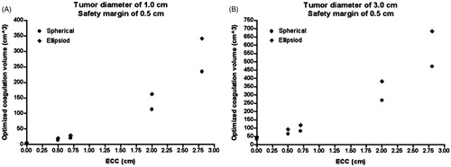
For a tumour diameter of 3.0 cm and a safety margin of 0.5 cm, the optimised coagulation volume is 33.5 cm3 assuming an ECC of 0 cm, 83.1 cm3 for an ECC of 0.7 cm and 471.5 cm3 for an ECC of 2.8 cm ().
Figure 7. Relationship between ECC and the optimised coagulation volume. The larger the ECC, the larger the optimised coagulation zone; the optimised coagulation volume is larger for ellipsoid coagulation shapes (B), compared with spherical coagulation shapes (A); for identical numerical values of ECC, PAOs (PAOsspec) can be different depending on the dislocation of the coagulation centre in relation to the tumour centre (see Tables).
PAO
If there is no dislocation of the coagulation centre in relation to the tumour centre (ex = 0 cm and ey = 0 cm), resulting in an ECC of 0 cm, PAO is 0.5 cm. If dislocation of the coagulation centre in relation to the tumour centre takes place in the applicator shaft direction by 0.5 cm (ex = 0.5 cm ey = 0 cm), resulting in an ECC of 0.5 cm, PAO is 1.5 cm. But if dislocation of the coagulation centre in relation to the tumour centre takes place perpendicular to the applicator shaft direction by 0.5 cm (ex = 0 cm and ey = 0.5 cm), resulting also in an ECC of 0.5 cm, PAO is only 1.0 cm. If dislocation of the coagulation centre in relation to the tumour centre takes place in the applicator shaft direction and perpendicular to the applicator shaft direction by 0.5 cm (ex = 0.5 cm and ey = 0.5 cm), resulting in an ECC of 0.7 cm, PAO increases to 1.7 cm.
Part 2: ellipsoid coagulation shapes
Specific definitions
The specific definitions for ECC and optimised coagulation short diameter for ellipsoid coagulation shapes are identical to ECC and optimised coagulation diameter for spherical coagulation shapes. The optimised coagulation volume for ellipsoid coagulation shapes is larger compared with the optimised coagulation volume for spherical coagulation shapes. In analogy to spherical coagulation shapes, a complex relationship exists between PAOspec and the determinants of ECC, which are ex and ey (the latter is not directly detectable in Equation 16 but hidden in CC).
Examples
Detailed data is listed in .
Table 2. Optimised coagulation zone for a tumour diameter of 1 cm (3 cm) and a safety margin of 0.5 cm for ellipsoid coagulation shapes.
Optimised coagulation volume
The optimised coagulation volume is larger for ellipsoid coagulation shapes compared with spherical coagulation shapes. If there is no dislocation of the coagulation centre in relation to the tumour centre, the maximum differences between ellipsoid coagulation shapes and spherical coagulation shapes are 1.5 cm3 (tumour diameter of 1.0 cm) and 11.7 cm3 (tumour diameter of 3.0 cm) (ex = 0 cm and ey = 0 cm) (). If there is dislocation of the coagulation centre in relation to the tumour centre, the maximum differences between ellipsoid coagulation shapes and spherical coagulation shapes are 113.9 cm3 (ex = 2.0 cm and ey = 0 cm), 113.9 cm3 (ex = 0.0 cm and ey = 2.0 cm), as well as 213.3 cm3 (ex = 2.0 cm and ey = 2.0 cm) for a tumour diameter of 3.0 cm.
PAOspec
PAOspec is always distinct from PAO even if identical dislocations of the coagulation centre in relation to the tumour centre are taken into account. Contrary to PAO, PAOspec is different between both tumour diameters for identical dislocations of the coagulation centre in relation to the tumour centre (single exception: ex = 0 cm and ey = 0 cm). Maximum differences for PAOspec between both tumour diameters are 0.7 cm (ex = 2.0 cm and ey = 0 cm), 0.7 cm (ex = 0 cm and ey = 2.0 cm) and 0.5 cm (ex = 2.0 cm and ey = 2.0 cm).
Discussion
In this work we describe a theoretical approach with considerations for its practical application to optimise the coagulation zone for thermal ablation procedures. By applying five equations for spherical coagulation shapes (Equations 8, 10–12 and 13), and additionally three equations for ellipsoid coagulation shapes (Equations 14–16), one uncovers the relationship between the optimised coagulation zone and ECC.
Basic considerations
Individual adaptation of the coagulation zone to the tumour extent is a prerequisite for organ-sparing thermal ablation. The better the coagulation centre corresponds to the tumour centre, the more healthy tissue can be preserved. One observation is that, if the width of the safety margin is kept constant, the volume of the safety margin disproportionately increases with larger tumour diameters. In these cases imperfect positioning of the applicator adds further unnecessary tissue destruction if complete tumour coverage is the goal. This is relevant due to the latest introduction of powerful thermal ablation systems (with power outputs ≥300 W), which allow for the destruction of large tissue volumes. Optimisation of the coagulation zone may help 1) to destroy larger tumours than commonly treated (e.g. 3 cm for hepatocellular carcinoma and 4 cm for renal cell carcinoma) and 2) to minimise complications (since the likelihood of complications increases with larger coagulation volumes) [Citation10,Citation13,Citation14]. An advantage of our approach may be its usability. The application of the tumour as a sphere (and consequently the safety margin sphere) has the inherent advantage that the entrance angle of the applicator shaft in relation to the tumour is irrelevant. Although objective imaging with 3D navigation can increase precision of thermal ablation procedures, it is unlikely that the applicator is perfectly positioned in relation to the tumour centre. Therefore, some ECC can be regarded as normal. Our theoretical approach with considerations for practical use describes how ECC can be quantified and minimised. It is feasible to optimise the coagulation zone without needing to repuncture simply by withdrawing or further pushing the applicator shaft into the tissue.
Theoretical approach
Impact of ECC on the optimised coagulation zone
Our examples for spherical and ellipsoid coagulation shapes demonstrate that ECC has substantial impact on the optimised coagulation zone: the larger the ECC, the larger the optimised coagulation zone. ECC can serve as a measure to estimate the optimised coagulation volume. It helps to decide if the puncture tract obtained after positioning of the applicator is acceptable, or if an alternative puncture tract is indicated which would reduce the coagulation volume.
Importance of PAO (PAOspec)
Basically, PAO (PAOspec) is a measure to obtain the optimal applicator tip position in relation to the tumour margin. From the clinical perspective, PAO (PAOspec) is an extremely important parameter. It is exceptionally associated with dislocation of the coagulation centre in relation to the tumour centre in the applicator shaft direction (ex). Ey is defined as being perpendicular to the applicator shaft direction, and therefore its numerical value can be reduced exclusively with a repuncture closer to the tumour centre. Ex is defined in the applicator shaft direction, and therefore its numerical value can be reduced and even neutralised by pulling back or pushing forward the applicator shaft. In other words, PAO (PAOspec) can be calculated in such a manner that the optimised coagulation zone is minimised by neutralising ex (at any given ey). Our examples for spherical (ellipsoid) coagulation shapes demonstrates that optimisation using PAO (PAOspec) eliminates an unnecessary coagulation volume of up to 203.4 cm3 (302.8 cm3) achieved by simply slightly withdrawing the applicator shaft while ensuring complete coverage of the tumour ( and , ).
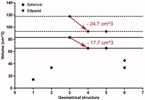
Figure 8. Minimisation of the optimised coagulation zone after positioning of the applicator without the need for repuncture (neutralisation of ex). 1 (on the geometrical structure axis), tumour sphere (diameter of 3.0 cm); 2, safety margin sphere (safety margin of 0.5 cm); 3–6, optimised coagulation zone for spherical (point) and ellipsoid (diamond) coagulation shapes (3, ex = 0.5 cm and ey = 0.5 cm; 4, ex = 0 cm and ey = 0.5 cm; 5, ex = 0.5 cm and ey = 0 cm; 6, ex = 0 cm and ey = 0 cm). After neutralisation of ex (ex = 0 cm) (red arrow), for spherical (ellipsoid) coagulation shapes an unnecessary coagulation volume of 17.7 cm3 (24.7 cm3) can be eliminated by slightly adjusting the applicator shaft by pulling back or pushing forward (for spherical (ellipsoid) coagulation shapes by reduction of PAO (PAOspec) from 1.7 cm to 1.0 cm (1.6 cm to 1.0 cm)).
Considerations for practical use
Our theoretical approach can be implemented in a clinical setting featuring CT-guided thermal ablation procedures with 3D image post-processing. After the applicator’s positioning based on standard image planes (transversal, coronal and sagittal), individual angulated image planes are necessary. Individual image angulation takes place in such a manner that conditions identical to the Cartesian coordinate system are applied. Therefore, the entire course of the applicator shaft as well as the tumour centre have to appear in one single image slice (master image slice) (). The master image slice includes the x-axis and the y-axis as is the case in the Cartesian coordinate system. The direction of the x-axis is defined in the direction of the applicator shaft, and the y-axis is defined perpendicular to the applicator shaft. In the master image slice, the distance between the applicator shaft and the tumour centre defines ey (). Calculation of PAO (PAOspec) follows according to Equation 12 (Equation 16) assuming ex = 0 cm. PAO (PAOspec) is then realised as the radial distance between the tumour margin and the applicator tip using the master image slice by pulling back or pushing forward the applicator shaft. The finesse of our approach is that ECC, optimised coagulation diameter (optimised CSD), optimised coagulation volume and PAO (PAOspec) are calculated with actual ey, but hypothetical ex = 0 cm after positioning of the applicator. If the optimised coagulation volume appears appropriate, neutralisation of ex is performed, and the ablation parameters (e.g. power output and ablation time) can be adjusted according to the coagulation short diameter, which is available from thermal ablation systems’ commercial information. If the optimised coagulation volume appears inappropriate, a repuncture closer to the tumour centre is then performed, which reduces ey. Compared with currently available methods for improved focal tumour ablation, our technique features the optimisation of PAO (PAOspec), which eliminates unnecessarily coagulated tissue and ensures complete coverage of the tumour. All this is accomplished without the need for repuncture by only a measured pulling back or pushing forward of the applicator shaft. As a result, complications due to multiple penetrations will be reduced (e.g. haemorrhage, bile leak or urinoma). It may be used to define the appropriate ablation parameters at a certain applicator position for complete tumour coverage on the one hand but organ-sparing thermal ablation on the other. With regard to these aspects, our approach can be regarded as clinically relevant.
Study limitations
Firstly, perfect spherical and ellipsoid coagulation shapes are unlikely to occur in clinical settings. Procedures can be performed with different applicator designs (e.g. straight needle, cluster or umbrella design), and the resulting coagulation zones, front margins and coagulation centres can vary. Secondly, this approach did not address thermal and electrical tumour inhomogeneities (leading to inhomogeneous heating), as well as the tumour’s proximity to sensitive anatomical structures [Citation17]. Nonetheless, our study has clinical implications since our method may serve to estimate and realise the optimised coagulation zone dependent on the actual position of the applicator. Thirdly, there is no data that shows our approach is actually feasible in the clinical setting and there is currently no data to illustrate the improved oncological outcome and the reduction of the complication rate. demonstrates the feasibility of imaging, and it is likely that this method should be easy to implement clinically. However, it does not demonstrate feasibility of optimisation of the method itself. For this reason, actual clinical data using this method, or data obtained from experimental animal models or even phantom modelling should be implemented in future trials.
Conclusion
In this work we describe a theoretical approach for the optimisation of the coagulation zone for thermal ablation procedures with consideration for its practical application. The theoretical approach is based on spherical and ellipsoid coagulation shapes to derive fundamental relationships between tumour diameter, safety margin, ECC and PAO. The considerations for practical use are implemented using a CT system with 3D imaging post-processing. It is demonstrated how the concept presented may be used to optimise the coagulation zone after the applicator is already positioned, thus preventing the need for re-puncture by simply adjusting the applicator shaft.
Declaration of interest
The authors report no conflicts of interest.
Acknowledgements
The authors thank Theresa Mokry and Theresa Gockner for their substantial support in creating the figures.
References
- Webb H, Lubner MG, Hinshaw JL. Thermal ablation. Semin Roentgenol 2011;46:133–41
- Clements T, Lin YK, Raman JD. Current status of ablative techniques for small renal masses. Expert Rev Anticancer Ther 2007;11:79–91
- Minami Y, Kudo M. Radiofrequency ablation of hepatocellular carcinoma: A literature review. Int J Hepatol 2011. doi.org/10.4061/2011/104685
- Widmann G, Bodner G, Bale R. Tumour ablation: Technical aspects. Cancer Imaging 2009;9:S63–7
- Brieger J, Pereira PL, Trübenbach J, Schenk M, Kröber SM, Schmidt D, et al. In vivo efficiency of four commercial monopolar radiofrequency ablation systems: A comparative experimental study in pig liver. Invest Radiol 2003;38:609–16
- Mulier S, Ni Y, Frich L, Burdio F, Denys AL, De Whispelaere JF, et al. Experimental and clinical radiofrequency ablation: Proposal for standardized description of coagulation size and geometry. Ann Surg Oncol 2007;14:1381–96
- Sommer CM, Arnegger F, Koch V, Pap B, Holzschuh M, Bellemann N, et al. Microwave ablation of porcine kidneys in vivo: Effect of two different ablation modes (“temperature control” and “power control”) on procedural outcome. Cardiovasc Intervent Radiol 2012;35:653–60
- Sommer CM, Koch V, Pap B, Bellemann N, Holzschuh M, Gehrig T, et al. Effect of tissue perfusion on microwave ablation: Experimental in vivo study in porcine kidneys. J Vasc Interv Radiol 2011;22:1751–7
- Sommer CM, Bryant M, Kortes N, Stampfl U, Bellemann N, Mokry T, et al. Microwave ablation in porcine livers applying 5-minute protocols: Influence of deployed energy on extent and shape of coagulation. J Vasc Interv Radiol 2012;23:1692–9
- Sommer CM, Lemm G, Hohenstein E, Bellemann N, Stampfl, U, Goezen AS, et al. CT-guided bipolar and multipolar radiofrequency ablation (RF ablation) of renal cell carcinoma: Specific technical aspects and clinical results. Cardiovasc Intervent Radiol 2013;36:731–7
- Berger WK, Poledna J. New strategies for the placement of cryoprobes in malignant tumors of the liver for reducing the probability of recurrences after hepatic cryosurgery. Int J Colorectal Dis 2001;16:331–9
- Oguro S, Tuncali K, Elhawary H, Morrison PR, Hata N, Silverman SG. Image registration of pre-procedural MRI and intra-procedural CT images to aid CT-guided percutaneous cryoablation of renal tumors. Int J Comput Assist Radiol Surg 2011;6:111–17
- Llovet JM, Bru C, Bruix J. Prognosis of hepatocellular carcinoma: The BCLC staging classification. Semin Liver Dis 1999;19:329–38
- Kudo M. Radiofrequency ablation for hepatocellular carcinoma: Updated review in 2010. Oncology 2010;78:113–24
- Wang X, Sofocleous CT, Erinjeri JP, Petre EN, Gonen M, Do KG, et al. Margin size is an independent predictor of local tumor progression after ablation of colon cancer liver metastases. Cardiovasc Intervent Radiol 2013;36:166–75
- Mulier S, Ni Y, Miao Y, Rosiere A, Khoury A, Marchal G, et al. Size and geometry of hepatic radiofrequency lesions. Eur J Surg Oncol 2003;29:867–78
- Clasen S, Schmidt D, Dietz K, Boss A, Kröber SM, Schraml C, et al. Bipolar radiofrequency ablation using internally cooled electrodes in ex vivo bovine liver: Prediction of coagulation volume from applied energy. Invest Radiol 2007;42:29–36
- Lobik L, Leveillee RJ, Hoey MF. Geometry and temperature distribution during radiofrequency tissue ablation: An experimental ex vivo model. J Endourol 2005;19:242–7