
Abstract
Purpose: A hyperthermia system using a folded loop antenna applicator at 27 MHz for soft tissue treatment was investigated both theoretically and experimentally to evaluate its clinical value. Materials and methods: The electromagnetic analysis of a 27-MHz folded loop antenna for use in human tissue was based on a customised software tool and led to the design and development of the proposed hyperthermia system. The system was experimentally validated using specific absorption rate (SAR) distribution estimations through temperature distribution measurements of a muscle tissue phantom after electromagnetic exposure. Various scenarios for optimal antenna positioning were also performed. Results: Comparison of the theoretical and experimental analysis results shows satisfactory agreement. The SAR level of 50% reaches 8 cm depth in the tissue phantom. Thus, based on the maximum observed SAR values that were of the order of 100 W/kg, the antenna specified is suitable for deep tumour heating. Conclusions: Theoretical and experimental SAR distribution results as derived from this study are in agreement. The proposed folded loop antenna seems appropriate for use in hyperthermia treatment, achieving proper planning and local treatment of deeply seated affected areas and lesions.
Introduction
Hyperthermia is a non-invasive therapeutic procedure for medical treatment in which body tissue is exposed to slightly higher temperatures to damage and kill cancer cells or to make them more sensitive. It is normally used as an adjuvant therapy, as it is most effective when used in conjunction with conventional therapies such as radiation and certain chemotherapy drugs. Hyperthermia is a promising technique to improve cancer treatment, but it still remains largely experimental and not in widespread use [Citation1–3].
Numerous applicators have been developed by various research groups in order to effectively perform hyperthermia treatment either at superficial or deeper sites of the human body. Microwave applicators can effectively concentrate and guide microwave energy in a specific region of the human body that requires treatment, while controlling the area where maximum specific absorption rate (SAR) is achieved. Waveguide applicators have been successfully proposed for subcutaneous cancer treatment occurring in small regions [Citation4] but also for subcutaneous diffuse cancer within curved parts of the human body [Citation5]. Single microstrip and planar antennas have been proposed for superficial hyperthermia [Citation6,Citation7]. Dual frequency conformal microstrip antennas [Citation5] and miniaturised low profile well-matched antennas have been studied [Citation8]. Recently, left-handed specific materials lenses have been used to improve the matching between the applicator–human body interface [Citation9]. Also, dual-mode microwave antennas for simultaneous hyperthermia treatment and microwave radiometric monitoring have been developed, allowing heating and thermometry with the same applicator [Citation10].
Taking into account previous developments and aiming to treat superficial or deeper seated tumours in the abdominal area effectively, we proposed the use of loop antennas for potential use in hyperthermia systems. The performance of a 27-MHz inductive loop antenna has been theoretically and experimentally studied by our group previously. Two inductive loop antennas with radii of 7 cm and 9 cm were developed and tested in phantom. While satisfactory SAR distribution curves were observed inside the loop, peak SAR values were observed in the phantom below the antenna’s periphery [Citation11]. To overcome this drawback, the performance of a folded loop antenna has been investigated in this study.
More specifically, theoretical electromagnetic analysis was carried out for the estimation of the electric field radiated by a folded loop antenna operating at 27 MHz inside the human body. Numerical results of the SAR distribution are presented for three different antenna locations with respect to the area under treatment. Next, the radiation characteristics of the applicator were validated with measurements using a customised E-field probe with shielded transmission lines. Finally, phantom experiments were performed using the proposed hyperthermia system. Temperature distribution inside a muscle tissue phantom was measured and SAR distribution curves were derived.
Materials and methods
Theoretical electromagnetic analysis
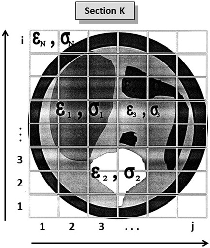
A semi-analytical method was developed for the calculation of the electric field inside the human body, when radiated by a folded loop antenna operating at 27 MHz. The specific method is based on the three-dimensional integral equations technique and on the method of moments. The geometry of the problem is depicted in . The human body torso is characterised by a heterogeneous dielectric permittivity distribution εr and a conductivity σ (S/m). Every anatomical structure (organ tissue) with common dielectric properties is described by a cluster of cells forming a grid of pixels for each planar cut transversal to the torso, sufficient to reconstruct the whole configuration. The structural information of the body torso is provided by CT or MRI Images. The tomographic image spatial resolution defines each cell dimension and consequently forms the εi, σi component grid of the solver tool ().
Figure 1. The geometry of the problem.
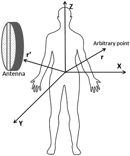
Figure 2. Grid of dielectric properties εr, σ.
The dielectric body response to a near field radiating antenna is the superposition of the incident field E0(r) and the polarisation field which also includes the polarisation current Ip(r). Therefore, the total induced field is described by Equation Equation1(1) [Citation12,Citation13].
(1)
where E(r) is the total electric field inside and outside the dielectric body, E0(r) is the antenna primary field in the absence of the dielectric body,
is the unit dyadic,
,
is the free space Green equation,
is the complex permittivity,
is the free space dielectric permittivity,
is the free space wavenumber and
is the free space permeability.
Application using the method of moments
The human body volume is divided into N cubes/voxels. It is assumed that the permittivity is constant in every elementary cubic cell and the electric susceptibility is defined by: of the j cube. It is also assumed that inside every cube the field remains stable, thus
,
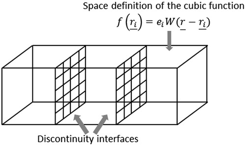
. Since the human body torso is described by a sum of finite voxels/cubic cells, the electric field is described by cubic function of the form
, where
Ei is the unknown field component and ri the position vectors of the cells’ centres of gravity. Using the cubic equations above as base functions, the electric field inside the dielectric media can be described by cubic pulses [Citation14] (), maintaining the discontinuity on the cube interfaces.
Figure 3. Cubic pulses.
Equation Equation1(1) becomes Equation Equation2
(2) .
(2)
where ri is the position vector and Vj is the volume of the j-th cube respectively, and
(3)
where
(4)
For calculation two cases are examined: (1) when i = j
(5)
where
for
and (2) when i ≠ j. Van Bladel [Citation15] has used the approximation:
(6)
which becomes
(7)
E0(ri) in Equation Equation3(3) is the electric field developed by the antenna’s induction without the intervention of the dielectric media and is given by Equation Equation8
(8)
(8)
where dl′ is the incremental length of integration, c is the antenna’s whole linear integration surface and
is the Green’s function. So it becomes Equation Equation9
(9) .
(9)
Customised software was developed using the above analysis based on the conjugate gradient method in conjunction with a convergence control method that was used for the electric field calculation at any arbitrary point of the configuration.
Applicator development
The 27-MHz radiation frequency was chosen due to the high expected penetration depth (∼7 cm). The antenna design and construction focused on achieving electrical field homogeneity and sufficient penetration depth. With this view, matching of the antenna to the generator should be ensured as well as low power consumption and overall system thermal stability.
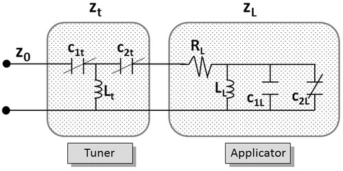
The double loop’s conductive part consisted of a brass strip of 1 mm thickness and 20 mm width. The power was supplied by a simple transformer with primary to secondary ratio of 16:4. The transmitter was connected to the antenna and a tuner was inserted in between to assure optimal matching. The antenna layout is depicted in where the impedances of the line (Z0), the resonator (Zt) and the radiator (ZL) are shown. Through testing and measurements it was concluded that a capacitor must be placed at the opposite side of the input transformer. It was also observed that a variable capacitor was also required so finally a combination of a stable (C1L) and a variable (C2L) capacitor was used. The tuner consists of an inductor Lt and two capacitors C1t and C2t as shown in . In addition the applicator consisting of the induction LL induced by the transformer and the antenna’s folded loops, the resistance RL and the two resonance capacitors C1L and C2L are depicted.
Figure 4. Tuner and applicator layout.
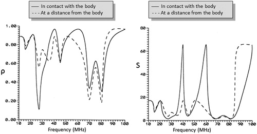
The ρ and S variation over frequency (f) was followed for a range from 10 MHz to 100 MHz and using the human body as a dielectric medium. The results are given in where it can be seen that the antenna is tuned to a frequency of 27 MHz.
Figure 5. Spectral frequency distribution of reflection coefficient (ρ) and standing waves ratio (S).
Development of an electric field probe with shielded transmission lines
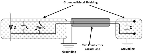
The design of the electric field (E-field) probe was based on a simple detector circuit followed by a diode and a resistor–capacitor (RC) filter. A double conductor coaxial line with external shield was used as a voltage transmission line in order to minimise the effects of the antenna field. In addition, copper shields were placed on the detector and a voltage multimeter (TELE GM-270) was placed at the edges of the instrument. All the shields were earthed in common through the frequency generator’s chassis. The details of the design are depicted in , where resistance R = 100 KΩ, capacitors C = 10 NF (noise figure) and C′ = 10 NF.
Figure 6. Internal detail of the E-field probe.
The electrical field of the applicator was measured by means of the field component on the z-axis of the phantom’s coordinate system, for all three polarisations.
The E-field probe exhibited satisfactory stability (little variation) and its indications were significantly differentiated in relation to the distance from the antenna’s centre and to the polarisation in the three dimensions. In addition, the E-field probe showed a field distribution in agreement with the theoretical results regarding the applicator radiation characteristics.
Results
Numerical results
Numerical code executions have been realised, using the same parameters that have been used in the experimental procedure. Specifically, theoretical calculations for SAR distribution have been performed for a folded loop antenna and a soft tissue phantom. A homogeneous area was divided into 6 × 14 × 12 = 1008 voxels of 2 cm. The dielectric properties of the homogeneous dielectric media were: εr = 112, σ = 0.76 Si/m. The geometry of the problem is shown in , where A and B are the two plane cuts in which the SAR distributions are calculated. The results of the normalised SAR values are presented in , and for three different antenna positioning scenarios with respect to the dielectric media.
Figure 7. The geometry of the experimental procedure.
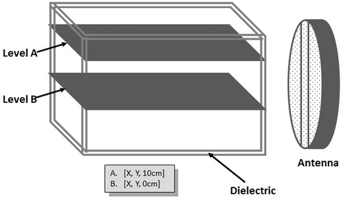
Figure 8. SAR distributions for antenna-dielectric media distance d = 0 cm (case I).
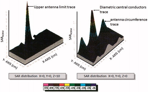
Figure 9. SAR distributions for antenna-dielectric media distance d = 3 cm (case II).
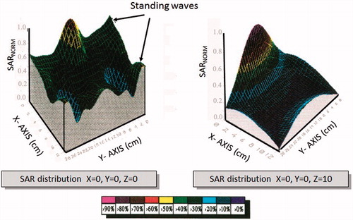
Figure 10. SAR distributions for antenna-dielectric media distance d = 9 cm (case III).
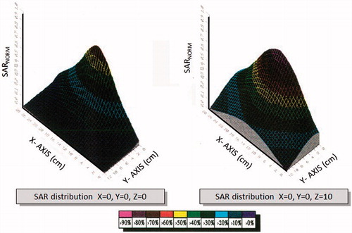
When the distance between the antenna and the dielectric media is 0 cm, The SAR maximum value is 210 W/kg and it can be justified by the antenna’s position. This is a local phenomenon that in a depth of 2 cm the SAR value is approximately 48 W/kg. Observing the above figures it can be concluded that the optimum penetration depth occurs in the second case (d = 3 cm) where the penetration depth for the 35% SAR is 7 cm and the maximum SAR value is 117 W/kg. Relatively high SAR values are observed on the dielectric’s periphery due to standing waves as the radiation wavelength and the dielectric dimensions are comparable. Finally, when the distance between the dielectric media and the antenna increases the SAR distribution becomes more homogeneous while the penetration depth and SAR maximum value decrease, as expected.
Experimental results: temperature measurement in muscle tissue phantom
The SAR values could be calculated using the following formula
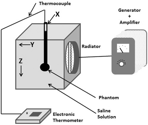
where k = 4184, c = 0.86 cal/°C/kgr is the material specific heat, Δθ is the temperature variation, Δt (s) is the heating time. The above equation provides a method of SAR calculation by measuring the variation of temperature over time. The experiments were carried out using the set-up shown in . The thermal sensor was placed inside a plastic cylinder containing the soft tissue phantom [Citation16]. The cylinder positioning permits movement along the three axes X, Y, Z, enabling raster scanning of the entire radiated area inside the saline solution (0.27%), as depicted in . The plastic container ensures the thermal isolation of the phantom from the saline solution. The suitable phantom mimicking human tissue behaviour at 27 MHz consisted of 79.73% water, 0.27% salt and 20% jelly. The phantom’s dielectric properties were measured using the coaxial line method and were found ε = 102.5 and σ = 0.63 Si/m, values very close to the values ε = 113 and σ = 0.6Si/m reported in literature.
Figure 11. Experimental set-up for temperature measurements.
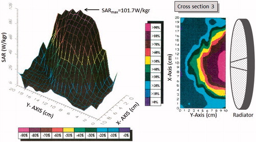
The SAR measurements were performed at three different transversal cuts along the z axis at different height levels as shown in . The temperature measurements were conducted with a spatial resolution of 1 cm, scanning a total volume of 10 × 10 × 10 cm. The results are presented both by 1) SAR distribution 3D plot for every transversal plane cut, and 2) SAR distribution contour plane according to the %SARNORM for every plane. The results for cross-sections 1, 2, 3 are depicted in . In all cases the output power was 300 W.
Figure 12. Three transverse plane cuts of temperature measurements.
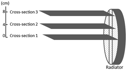
Figure 13. SAR distribution for cross-section 1.
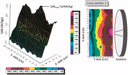
Figure 14. SAR distribution for cross-section 2.
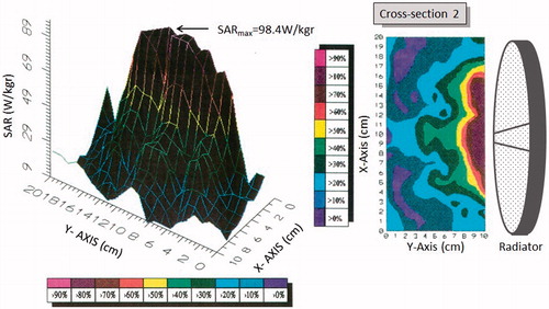
Figure 15. SAR distribution for cross-section 3.
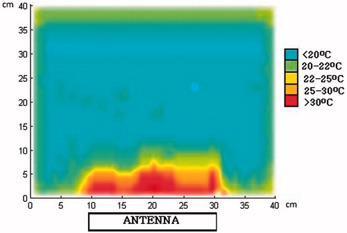
We then performed an experimental set-up with 10 rectangular Plexiglas containers filled with the same semi-solid phantom as the previous measurements. The dimensions of the Plexiglas containers were 40 × 40 × 2 cm. The antenna was placed as shown in , while the 10 Plexiglas containers covered the whole surface of the applicator for matching. We used a FLIR© T450sc (Wilsonville, OR) infrared (IR) camera. The antenna was operated with 300 W for 3 min. Then the first five containers were separated and a thermographic IR image was taken at the central plane (as shown in ). The IR image is shown in .
Figure 16. The experimental set-up with the Plexiglas containers filled with soft tissue phantom with the applicator in contact with the containers. The IR image was taken at the central plane.
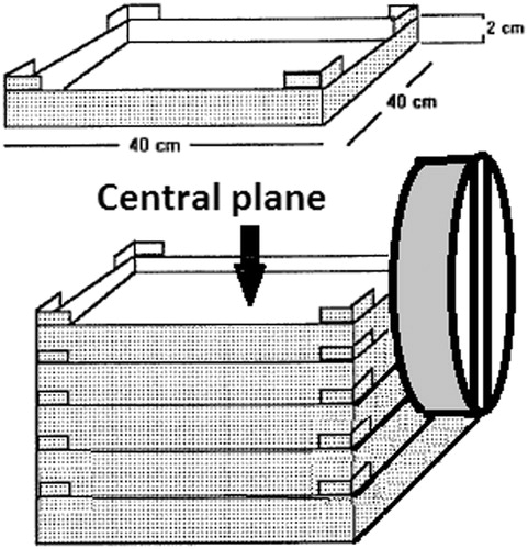
Figure 17. IR temperature profile at the central plane of the Plexiglas containers.
Discussion and conclusions
The effectiveness of hyperthermia treatment is related to the temperature achieved during the treatment, and for tumours located on the surface of the body, or close to it, the electromagnetic field energy can be applied through external applicators. In this paper, the performance of a 27-MHz folded loop antenna as a potential applicator in hyperthermia treatment was studied theoretically and in phantom experiments. The experimental results for SAR distribution matched the theoretical results derived from the computational program. It was observed that 50% of SAR reaches the 8-cm depth.
It was observed that in cross-sections 2 and 3, (, ) the SAR distribution was limited to inside the antenna’s physical boundaries. Thus it was concluded that there was a relative incident propagation of the electromagnetic radiation and the field lateral width does not increase significantly during its propagation inside the phantom.
At the first level it was observed that SAR distribution was at its maximum at the centre of the applicator and dropped slightly to smaller values at the periphery, maintaining a relative homogeneity. Therefore, it can be concluded that using the folded loop antenna, the heterogeneity in radiation distribution of a classic inductive loop is considerably rectified. The IR pattern in has the same morphology as the SAR measurements in , assuring the reliability of both measurements concerning the SAR distributions inside the phantom produced by the antenna. Moreover, the experimental set-up in minimised the artefacts of water circulation potentially influencing the temperature measurements.
Since the higher observed SAR values were of the order of 100 W/kg, it can be concluded that the specific applicator is sufficient for deep tumour heating and at significantly lower cost. The EM field scattered around the target area was calculated to be less than 20% of the maximum SAR. As shown in , at the area 1 cm outside the geometrical limits of the antenna the SAR is reduced by 20%. However, values of 30% of SAR are calculated at the geometrical limits of the phantom due to stationary waves. This effect should be taken into account during clinical use of the applicator, since 30% of SAR values might be significant in the surrounding environment (nurse) because of stationary waves. As shown in , the circulating water might affect the measurements. However, we choose this method of measurement for three reasons: 1) the procedure was simple and with low requirements, 2) the time of ‘power on’ was less than 2 min and consequently the phenomenon of circulating water would not be so powerful as to affect the measurements, while we gave also 5 min of relaxation time between measurements to achieve a steady state of water temperatures and water circulations, 3) the phenomenon of water circulation would be definitely present inside the human body, giving a ‘realistic’ simulation of our measurements.
The results above are comparable and similar to those reported by other research groups that have used circular or loop-based antenna set-ups for hyperthermia treatment and at a variety of operation frequencies [Citation1–3,Citation17]. With our study we are sharing our experience concerning the introduction of a new deep heating system which has some new advantages with the already reported systems in the literature:
it is simple in the construction
the applicator seems stable
the SAR distributions are showing a penetration depth of 8 cm, by means of the potential use of two or more applicators for focusing the electric field in the tumour in the same way as in radiotherapy with multiple fields
the power needed is really low (around 300 W) allowing the application of one amplifier at the level of more than 800 W with multiple applicators
comparable antennas for surface heating have SAR of the order of 30 W/kg, while our applicator has SAR value up to 100 W/kg allowing the application of deep heating and most importantly at low cost.
As a comment, our phantom was simplistic, making our measurements less reliable, while further results will be demonstrated with a heterogeneous phantom with a more realistic multilayer model performing more sophisticated temperature monitoring [Citation18,Citation19]. And last but not least, our applicator would also be suitable for use in a phased-array system for deep hyperthermia treatment [Citation20]. This work is ongoing and further results will be reported in the near future. Additionally, in order to validate the potential clinical value of the hyperthermia system presented in this paper, in vivo animal experiments are required in the future.
Acknowledgements
We wish to thank Alfred Baritz for editing the English language of our manuscript.
Declaration of interest
The authors report no conflicts of interest. The authors alone are responsible for the content and writing of the paper.
References
- Paulides MM, Stauffer PR, Neufeld E, Maccarini P, Kyriakou A, Canters RA, et al. Simulation techniques in hyperthermia treatment planning. Int J Hyperthermia 2013;29:346–57
- Shafirstein G, Feng Y. The role of mathematical modelling in thermal medicine. Int J Hyperthermia 2013;29:259–61
- Bruggmoser G. Some aspects of quality management in deep regional hyperthermia. Int J Hyperthermia 2012;28:562–9
- Rietveld PJM, Van Putten WLJ, Van Der Zee J, Van Rhoon GC. Comparison of the clinical effectiveness of the 433 MHz lucite cone applicator with that of a conventional waveguide applicator in applications of superficial hyperthermia. Int J Radiat Oncol Biol Phys 1999;43:681–7
- Gupta RC, Singh SP. Elliptically bent slotted waveguide conformal focused array for hyperthermia treatment of tumors in curved region of human body. Prog Electromagn Res 2006;62:107–25
- Montecchia F. Microstrip-antenna design for hyperthermia treatment of superficial tumors. IEEE Trans Biomed Eng 1992;39:580–8
- Prior MV, Lumori MLD, Hand JW, Lamaitre G, Schneider CJ, van Dijk JDP. The use of a current sheet applicator array for superficial hyperthermia: Incoherent versus coherent operation. IEEE Trans Biomed Eng 1995;42:694–8
- Halheit H, Vander Vorst A, Tedjini S, Touhami R. Flexible dual-frequency applicator for local hyperthermia. Int J Antenn Propag 2012; ID 389214
- Gong, Y, Wang G. Superficial tumor hyperthermia with flat left-handed metamaterial lens. Prog Electromagn Res 2009;98:389–405
- Jacobsen S, Stauffer PR, Neuman DG. Dual-mode antenna design for microwave heating and noninvasive thermometry of superficial tissue disease. IEEE Trans Biomed Eng 2000; 47:1500–9
- Kouloulias V, Uzunoglu N, Kouvaris J, Dardoufas C, Vlahos L. A new SAR system in 27 MHz for deep-heating hyperthermia. SAR theoretical distributions estimation of the antenna’s field and temperature measurements in a soft tissue phantom. 19th annual ESTRO meeting, Instabul 2000. Radiother Oncol 2000;56:A850
- Harrington RF. Matrix methods for field problems. Proc IEEE 1967;55:136–49
- Ney MM. Method of moments as applied to electromagnetic problems. IEEE Trans Microw Theory Tech 1985;33:972–80
- Tsai, CT, Massoydi H, Durney C, Iskander M. A procedure for calculating fields inside arbitrarily shaped, inhomogeneous dielectric bodies using linear basis function with the method of moment. IEEE Trans Microw Theory Tech 1986;34:1131–9
- Van Bladel J. Some remarks on Green’s dyadic for infinite space. IRE Trans Anten Prop 1961;9:563–6
- Shneider C, de Leeuw A, van Dijk J. Quantitative determination of SAR profiles from photographs of the light-emitting diode matrix. Int J Hyperthermia 1992;8:609–20
- Salahi S, Maccarini PF, Rodrigues DB, Etienne W, Landon CD, Inman BA, et al. Miniature microwave applicator for murine bladder hyperthermia studies. Int J Hyperthermia 2012;28:456–65
- Saccomandi P, Schena E, Silvestri S. Techniques for temperature monitoring during laser-induced thermotherapy: An overview. Int J Hyperthermia 2013;29:609–19
- Numan WC, Hofstetter LW, Kotek G, Bakker JF, Fiveland EW, Houston GC, et al. Exploration of MR-guided head and neck hyperthermia by phantom testing of a modified prototype applicator for use with proton resonance frequency shift thermometry. Int J Hyperthermia 2014;30:184–91
- Juang T, Stauffer PR, Craciunescu OA, Maccarini PF, Yuan Y, Das SK, et al. Thermal dosimetry characteristics of deep regional heating of non-muscle invasive bladder cancer. Int J Hyperthermia 2014;30:176–83